Article

Phase Transformation and Superstructure Formation in (Ti0.5, Mg0.5)N Thin Films through High-Temperature Annealing

Department of Physics, Chemistry and Biology (IFM), Linköping University, SE-581 83 Linköping, Sweden
*
Author to whom correspondence should be addressed.
Coatings 2021, 11(1), 89; https://doi.org/10.3390/coatings11010089
Submission received: 10 December 2020 / Revised: 8 January 2021 / Accepted: 12 January 2021 / Published: 14 January 2021
(This article belongs to the Special Issue Magnetron Sputter Deposition of Nitride Thin Films and Nanostructures)

Abstract

:
(Ti0.5, Mg0.5)N thin films were synthesized by reactive dc magnetron sputtering from elemental targets onto c-cut sapphire substrates. Characterization by θ–2θ X-ray diffraction and pole figure measurements shows a rock-salt cubic structure with (111)-oriented growth and a twin-domain structure. The films exhibit an electrical resistivity of 150 mΩ·cm, as measured by four-point-probe, and a Seebeck coefficient of −25 µV/K. It is shown that high temperature (~800 °C) annealing in a nitrogen atmosphere leads to the formation of a cubic LiTiO2-type superstructure as seen by high-resolution scanning transmission electron microscopy. The corresponding phase formation is possibly influenced by oxygen contamination present in the as-deposited films resulting in a cubic superstructure. Density functional theory calculations utilizing the generalized gradient approximation (GGA) functionals show that the LiTiO2-type TiMgN2 structure has a 0.07 eV direct bandgap.

1. Introduction

Titanium nitride-based hard coatings [1,2,3] have a long history for use in applications such as protective layers and hard coatings. Thus, the search for TiN based alloys has led to the development of an extensive series of alloys, e.g., Ti–Si–N [4,5] and Ti–Al–N [6,7,8]. Among the many TiN-based compounds, titanium-magnesium nitride (Ti0.5, Mg0.5)N [9,10,11] is of particular interest due to its semiconducting properties, which motivates research on electronic and energy-related applications. Previous attempts to synthesize (Ti1−x, Mgx)N [12,13,14,15,16,17] aimed at studying (Ti1−x, Mgx)N growth and properties, such as oxidation resistance in comparison to pure TiN or use as a decorative coating due to color variations. However, research in (Ti1−x, Mgx)N alloys gained additional interest due to the research regarding the thermoelectric properties of rock-salt cubic scandium nitride (ScN).
ScN [18,19,20,21,22] exhibits a relatively large thermoelectric power factor of (2.5–3.5) × 10−3 Wm−1·K−2. However, the relatively high thermal conductivity [23,24,25,26] of approximately 8–12 Wm−1·K−1 results in a low thermoelectric figure of merit (zT). To address this issue, Alling [27] studied (Ti1−x, Mgx)N alloys and a hypothetical semiconducting TiMgN2 superstructure using density functional theory (DFT) and proposed that by replacing the group-3 element scandium with a group-2 alkaline earth element (magnesium) and a group-4 transition metal (titanium), it is possible that the resulting compound will have a similar power factor to that of ScN, but with a reduced thermal conductivity. The study predicted the stability of a naturally layered B1-L11 superstructure TiMgN2, and that the possible reduced thermal conductivity may stem from interface phonon scattering. The Kohn-Sham band structure calculations predicted stoichiometric TiMgN2 to have a 1.11 eV bandgap using the HSE06 [28] hybrid functional. Irokawa and Usami [29] predicted similar results using the generalized gradient approximation (GGA) for predicting the band-structure using Perdew-Burke-Ernzerhof (PBE) functional, [30] which is qualitatively accurate in predicting the existence of band-structure energy gaps.
In a previous paper [31], we studied different crystal structures with an ABN2 stoichiometry (A and B being elements), concluding that stoichiometric and elementally pure TiMgN2 is stable in the NaCrS2 superstructure (which is equivalent to the B1-L11 depending on viewpoint direction) and predicted its thermoelectric power factor to be larger compared to ScN. Furthermore, ZrMgN2 and HfMgN2 were also predicted to be thermoelectric semiconductors that may crystallize in either the hexagonal NaCrS2 superstructure or the LiUN2 prototype monoclinic structure. These compounds were all predicted to be thermodynamically stable, suggesting that they can be synthesized by physical vapor deposition. Synthesis of MgxZr2−xN2 by Bauers et al. [32] confirms semiconducting properties through temperature-activated conductivity measurements and an onset in the optical absorption spectrum.
Here, we synthesized (Ti0.5, Mg0.5)N thin film alloys and annealed them at high temperatures in a pure nitrogen gas flow. In addition to studying (Ti0.5, Mg0.5)N and its thermoelectric properties, post-annealed (Ti0.5, Mg0.5)N are investigated for the formation of any superstructure and/or other secondary phases.

2. Materials and Methods

Depositions were performed by reactive dc magnetron sputtering in an ultra-high vacuum chamber [33]. The films were deposited onto (0001) sapphire substrates (10 mm × 10 mm × 0.5 mm), ultrasonically cleaned with commercially available detergents (3 min), de-ionized water, acetone and ethanol (10 min each) and blown dry using N2. The details of the cleaning method and detergent can be found elsewhere [34]. The substrates were heated 400 °C for one hour prior to the deposition process; the temperature was maintained until the end of the process. The films were deposited using 5-cm-diameter Ti (99.95% pure, Kurt J. Lesker, East Sussex, UK) and Mg (99.95% pure, MaTeck, Jülich, Germany) targets and an argon/nitrogen gas mixture (99.9997% pure for both gases). The deposition pressure was set to 0.65 Pa (4.9 mTorr). The substrate holder was rotated with a speed of 15 rpm and at floating potential. The deposition time was 120 min for the 28% nitrogen gas mixture (25 sccm N2, 65 sccm Ar).
Most of the characterization approach is analogous to our previous work [35]. X-ray diffraction (XRD) θ–2θ scans were measured in a PANalytical X’Pert PRO diffractometer system (Cu Kα) (Malvern Panalytical, Almelo, The Netherlands) operated at 45 kV and 40 mA. The incident optics was a Bragg-Brentano module including a 0.5° divergence slit and a 0.5° anti-scatter slit, and the diffracted optics included a 5.0 mm anti-scatter slit and 0.04 rad Soller slits. The solid-state detector was set to one dimensional scanning line mode. Step sizes and collection times per step of 0.004° and 2 s, respectively. Pole figures were acquired in a PANalytical EMPYREAN diffractometer (point focus mode, 45 kV and 40 mA, Malvern Panalytical, Almelo, The Netherlands). A 2 mm × 2 mm crossed slit X-ray lens and a parallel plate collimator as the incident and diffracted beam optics was used, respectively. Pole figures of the (Ti0.5, Mg0.5)N 111 peak were acquired for the tilt-angle (ψ) range from 0° to 85° and azimuth-angle (φ) range between 0° and 360° with steps of 5° for both ψ and φ and a collection time of 1 s.
The chemical composition of the film annealed at 820 °C was determined from X-ray photoelectron spectroscopy (XPS, Axis Ultra DLD, Kratos Analytical, Manchester, UK) equipped with a monochromatic Al Kα X-ray radiation (hν = 1486.6 eV) source. The base pressure in the analysis chamber during acquisition was less than 1 × 10⁻⁹ mbar. Survey spectra and core-level spectra of the Ti 2p, N 1s, Mg 1s, and O 1s regions were recorded as a function of sputter etch time up to 120 min. For that, a 0.5 keV Ar+ ion beam with an incidence angle of 20° from the surface and rastered over an area of 3 mm × 3 mm was used. Charge compensation was necessary to employ during measurements due to non-conducting substrates. The core-level spectra recorded after Ar+ etching was used to extract the chemical composition of the film. Here, a Shirley-type background was subtracted, and elemental cross sections provided by Kratos Analytical were applied. Due to preferential sputtering of nitrogen, a 5% error bar is expected [36].
Scanning electron microscopy (SEM) was performed in a LEO 1550 Gemini SEM (Zeiss, Oberkochen, Germany) operated at 5 kV acceleration voltage. The metal-to-atom ratio was determined by an energy dispersive X-ray spectroscopy (EDS, Oxford Instruments, Abingdon, UK) setup with the acceleration voltage set to 20 kV. High resolution-scanning transmission electron microscopy (HR-STEM) was performed in a Titan3 60–300 (FEI, Hillsboro, OR, USA). An FEI Tecnai G2 TF20 (Hillsboro, OR, USA) with a field-emission gun operating at 200 kV was used for selected area electron diffraction (SAED). Cross-sectional samples for the TEM were prepared by mechanical polishing to ~55 µm by hand. Ion milling was then performed using a Precision Ion Polishing System (PIPS, Gatan, Pleasanton, CA, USA) with a 5 keV Ar+ ion beam, angle of incidence 8° relative to the sample surface for 2 h, and 5° for 4 h. Once electron transparency was reached, a final ion milling step was applied with lower energy ion beams (2 keV) for 30 min.
The electrical resistivity of all samples was obtained by measuring the sheet resistance of the films with a four-point-probe RM3000 station (Jandel, Leighton Buzzard, UK). The measured sheet resistance was multiplied with the film thickness of approximately 250 nm (from cross-section SEM, ±10 nm) to obtain the resistivity. The Seebeck coefficient was obtained by an in-house setup described elsewhere [37]. Measurements were conducted in open-air conditions and the temperature gradient over the sample was approximately 50 °C. Sample annealing was done in an air-tight furnace with a nitrogen gas flow. Each annealing session was done for 30 min at 610, 770, and 820 °C. A final annealing session at 820 °C was also done for 1 h.
Density functional theory calculations were performed to study the electronic band structure of a LiTiO2-type (I41/amd) TiMgN2 structure. First-principles calculations were performed using DFT [38,39] with the projector augmented wave method (PAW) [40] as implemented in the Vienna ab initio simulation package (VASP) [41,42,43] version 5.2. Electronic exchange-correlation effects and the electronic band structure were modeled with the generalized gradient approximation (GGA) using the Perdew-Burke-Ernzerhof (PBE) functional [30]. The Kohn-Sham gaps of standard GGA calculations are systematically smaller than experimental bandgaps, but the results are suitable for qualitative research. The plane wave energy cutoff was set at 600 eV. The required structure files for the crystal structures were obtained from the Inorganic Crystal Structure Database (ICSD) and converted to VASP input files using cif2cell [44]. The band structure illustrations were prepared by the high-throughput toolkit (httk) [45], and the crystal structures by Visualization for Electronic and STructural Analysis (VESTA) [46].
The present work uses the same correction of the N2 energy as used in the Materials Project, based on work by Wang et al. [47]. It is known that standard GGA exchange-correlation functionals in DFT, have systematic errors in the prediction of energy differences between solid and gas phase systems [48]. Hence, it is common to adjust the gas phase energy in order to reproduce the formation energy of a system relative to a gas end-point.
The calculations used a 4 × 4 × 4 k-point mesh for Brillouin zone sampling generated with the Monkhorst-Pack scheme [49]. For band structure calculations, the tetrahedron method was used to obtain bandgap values with spin polarization included [50].

3. Result and Discussion

Figure 1 shows a θ–2θ scan of a (Ti0.5, Mg0.5)N random alloy as-deposited film on a c-cut sapphire substrate. The 111 peak from a face-centered cubic TiN structure of the film is observed next to the sapphire 0006 substrate peak. The inset shows a pole figure measurement of the (Ti0.5, Mg0.5)N thin film. The pole figure is performed at 2θ = 36.30° corresponding to diffraction from the (111) lattice plane. In this case, six high-intensity poles at ψ = 70° surround the center pole due to twin-domain growth which is expected for the growth of a cubic material on sapphire substrates. Based on the peak position, the lattice parameter for (Ti0.5, Mg0.5)N is approximately a0 = 4.30 Å. Assuming the theoretical lattice parameter of 4.44 Å for MgN50, 4.25 Å for TiN (Materials Project database) and Vegard’s law for a 50–50 random alloy, the theoretical lattice parameter value for (Ti0.5, Mg0.5)N would be approximately 4.35 Å.
Figure 2 shows the post-annealing θ–2θ scans of a (Ti0.5, Mg0.5)N film after 30 min of heat treatment in pure nitrogen. After annealing at 610 °C, the 111 peak shows a shift towards a larger 2θ angle, presumably resulting from stress relaxation in the film. However, after annealing at 770 °C, a small peak located at 2θ ~19° shows the presence of a phase with a relatively large lattice parameter. After annealing at 820 °C, this peak becomes more pronounced (marked by an arrow in Figure 2).
In order to further develop the phase transformation seen in Figure 2, the film was then annealed for an additional hour at 820 °C, yielding a set of more pronounced XRD peaks located at 2θ = 18.25°, 36.88°, 56.75°, and 78.53° seen in Figure 3. These peaks are multiples of each other (Table 1). The additional peak located at 2θ = 19.18° originates from a spinel phase, MgAl2O4, most likely formed by a reaction between the film and the substrate [51].
Figure 4a shows an SEM image of the as-deposited film surface. The film is porous and has a columnar-type growth, consistent with the relatively low deposition temperature of 400 °C, which was chosen due to the relatively high vapor pressure of magnesium. EDS measurements show that the as-deposited (Ti0.5, Mg0.5)N film has a 1:1 Ti/Mg atom ratio. The room-temperature in-plane electrical resistivity of the as-deposited film is measured to be 150 mΩ·cm, several orders of magnitude higher than pure TiN (20 µΩ·cm [52]). This is due to the addition of magnesium, consistent with the fact that magnesium nitride is a semiconductor. Note that magnesium nitride has the Mg3N2 stoichiometry, and that the stabilized mononitride MgN (due to the TiN structure) would be highly prone to oxidation in pure form. The room-temperature Seebeck coefficient is measured to be approximately −25 µV/K, lower but of the same order of magnitude as ScN.
Figure 4b–d show SEM images of the surface morphology after annealing, showing a major change in the surface morphology. Further annealing of the sample for one hour at 820 °C fully transforms the surface morphology from the initial columnar growth, as seen in Figure 4e.
Figure 5 shows a Z-contrast high-resolution scanning transmission electron microscopy (HR-STEM) image of the (Ti0.5, Mg0.5)N film annealed at 820 °C for one hour. The image shows a 5 nm × 10 nm nanoinclusion superstructure inside the (Ti0.5, Mg0.5)N rock-salt cubic matrix and positioned in between grain boundaries. The inset in Figure 5 shows the selected area electron diffraction (SAED) of the nanoinclusion showing a cubic structure along the [11 2 ¯ ] direction. However, these nanoinclusions have a lattice constant twice as large compared to the rock-salt (Ti0.5, Mg0.5)N alloy, and form as an ordered superstructure on the same underlying lattice after the temperature-activated phase transformation.
An XPS depth profile (Figure 6) was performed on the (Ti0.5 Mg0.5)N alloy film (annealed at 820 °C) to study oxidation effects. The results show that this annealed sample is highly inhomogeneous. Mg and O are the only elements present at the surface and the quantitative analysis suggests stoichiometric MgO formation. This could explain the surface morphology change seen in Figure 4, indicating continued oxidation during annealing processes. The porous features of the as-deposited film are most likely the source of the oxygen in the film when removing it from the UHV chamber. After prolonged sputter-etching, the film consists of approximately 24 at.% titanium, 21 at.% nitrogen, 19 at.% magnesium and 36 at.% oxygen. Due to the lack of an internal charge reference, the reliable determination of the bonding character cannot be attempted [53]. Nevertheless, the Ti 2p spectrum shows that Ti atoms are present in multiple chemical states likely involving Ti–N, Ti–Ox–Ny, and Ti–O bonding. EDS measurements (Figure 7) shows that the post-annealed film consists of titanium-rich and magnesium-rich regions (~10 nm in size) with a nanometer-sized boundary layer in between. These results, coupled with the HR-STEM, show that the phase transformation initially identified by XRD is due to Ti/Mg oxynitride nanoinclusions that form in between grain boundaries. These nanoinclusions show a similar structure to that of the LiTiO2-type cubic structure [54] (Figure 8, top image) and hint towards TiMgN2 formation being oxidized during the annealing process due to the initial presence of oxygen in the porous film. The predicted structure has an a = b = c = 8.635 Å lattice parameter at α = β = γ = 90° and a unit cell volume of approximately 644 Å3 (Niggli-reduced cell: a = b = c = 6.106 Å and α = β = γ = 60°). Note that the electron count for phase pure LiTiO2 (Li1+ Ti4+ O2− O2−) is +1, and thus it would not be a semiconductor, although DFT calculations of TiMgN2 crystallized in the LiTiO2-type cubic structure predicts an electronic band structure (Figure 8, bottom image) with a 0.07 eV direct bandgap. The predicted band structure uses the PBE GGA functional, which systematically gives Kohn-Sham bandgaps that are smaller than experimentally observed gaps. This means that since we find the existence of a bandgap in our calculations, the material would, if existing, display an even larger gap.
It should be noted that neither the NaCrS2 nor the LiUN2 structures regarding the hypothetical TiMgN2 structure are observed experimentally here. This could be explained by the oxygen present in the film which may drive the phase transformation towards a cubic superstructure. Also, it is possible that a cubic superstructure is preferred over the layered NaCrS2 structure when the starting crystal structure is rock-salt cubic.

4. Conclusions

(Ti0.5, Mg0.5)N thin films with a 1:1 metallic atom ratio were synthesized by reactive magnetron sputter deposition onto c-cut sapphire substrates. (Ti0.5, Mg0.5)N is a semiconductor, and exhibits a Seebeck coefficient value of a −25 µV/K and an electrical resistivity of 150 mΩ·cm at room temperature. Thermal annealing of (Ti0.5, Mg0.5)N results in the formation of a cubic superstructure in the form of a LiTiO2-type nanoinclusion inside the rock-salt cubic solid solution. Due to the presence of oxygen in the film, the nanoinclusions are a Ti/Mg-based oxynitride; such a quaternary phase may show interesting semiconducting properties. DFT calculations for a stoichiometric TiMgN2 crystallized in the LiTiO2 structure predict that this superstructure has a direct bandgap of 0.07 eV. It is possible that a Ti/Mg oxynitride with semiconducting properties would show high oxidation resistance, making it a suitable choice for research regarding high-temperature applications (e.g., thermoelectrics). Additional research could also focus on the synthesis and annealing of denser and oxygen-free thin films, preferably at higher temperatures.

Author Contributions

Conceptualization, M.A.G., R.A., B.A., and P.E.; formal analysis, M.A.G., A.l.F., J.L., G.G., R.A., B.A., and P.E.; investigation, M.A.G., A.l.F., J.L., G.G., R.A., B.A., and P.E.; writing—original draft preparation, M.A.G.; writing—review and editing, A.l.F., J.L., G.G., R.A., B.A., and P.E.; supervision, R.A., B.A., and P.E.; funding acquisition, R.A., B.A., and P.E. All authors have read and agreed to the published version of the manuscript.

Funding

The authors acknowledge funding from the Swedish Government Strategic Research Area in Materials Science on Functional Materials at Linköping University (Faculty Grant SFO-Mat-LiU No. 2009 00971), the Knut and Alice Wallenberg foundation through the Wallenberg Academy Fellows program (P.E.) KAW-2020.0196 and Wallenberg Scholar Grant No. KAW-2018.0194, and the Swedish Research Council (VR) under project No. 2016-03365 and No. 2019-05403. B.A. also acknowledges support from the Swedish Foundation for Strategic Research through the Future Research Leaders 6 program, FFL 15-0290. The computations were enabled by resources provided by the Swedish National Infrastructure for Computing (SNIC) at NSC partially funded by the Swedish Research Council through grant agreement No. 2018-05973.

Institutional Review Board Statement

Not applicable.

Informed Consent Statement

Not applicable.

Data Availability Statement

Data is contained within the article or available on reasonable request.

Conflicts of Interest

The authors declare no conflict of interest.

References

  1. Sundgren, J.-E. Structure and properties of TiN coatings. Thin Solid Films 1985, 128, 21–44. [Google Scholar] [CrossRef]
  2. Hultman, L. Thermal stability of nitride thin films. Vacuum 2000, 57, 1–30. [Google Scholar] [CrossRef]
  3. Mayrhofer, P.H.; Mitterer, C.; Hultman, L.; Clemens, H. Microstructural design of hard coatings. Prog. Mater. Sci. 2006, 51, 1032–1114. [Google Scholar] [CrossRef]
  4. Hultman, L.; Bareno, J.; Flink, A.; Söderberg, H.; Larsson, K.; Petrova, V.; Odén, M.; Greene, J.E.; Petrov, I. Interface structure in superhard TiN–SiN nanolaminates and nanocomposites: Film growth experiments and ab initio calculations. Phys. Rev. B 2007, 75, 155437. [Google Scholar] [CrossRef]
  5. Diserens, M.; Patscheider, J.; Lévy, F. Improving the properties of titanium nitride by incorporation of silicon. Surf. Coat. Technol. 1998, 108–109, 241–246. [Google Scholar] [CrossRef]
  6. Münz, W.-D. Titanium aluminum nitride films: A new alternative to TiN coatings. J. Vac. Sci. Technol. A 1986, 4, 2717. [Google Scholar] [CrossRef]
  7. Leyendecker, T.; Lemmer, O.; Esser, S.; Ebberink, J. The development of the PVD coating TiAlN as a commercial coating for cutting tools. Surf. Coat. Technol. 1991, 48, 175–178. [Google Scholar] [CrossRef]
  8. Hörling, A.; Hultman, L.; Odén, M.; Sjölén, J.; Karlsson, L. Mechanical properties and machining performance of Ti1−xAlxN-coated cutting tools. Surf. Coat. Technol. 2005, 191, 384–392. [Google Scholar] [CrossRef]
  9. Wang, B.; Kerdsongpanya, S.; McGahay, M.E.; Milosevic, E.; Patsalas, P.; Gall, D. Growth and properties of epitaxial Ti1−xMgxN(001) layers. J. Vac. Sci. Technol. A 2018, 36, 061501. [Google Scholar] [CrossRef]
  10. Baiwei, B.; Gall, D. A new semiconductor: Ti0.5Mg0.5N(001). In Proceedings of the 2018 IEEE Nanotechnology Symposium (ANTS), Albany, NY, USA, 14–15 November 2018. [Google Scholar]
  11. Sun, W.; Bartel, C.J.; Arca, E.; Bauers, S.R.; Matthews, B.; Orvañanos, B.; Chen, B.-R.; Toney, M.F.; Schelhas, L.T.; Tumas, W.; et al. A map of the inorganic ternary metal nitrides. Nat. Mater. 2019, 18, 732–739. [Google Scholar] [CrossRef] [Green Version]
  12. Banakh, O.; Balzer, M.; Fenker, M.; Blatter, A. Spectroellipsometric evaluation of colour and oxidation resistance of TiMgN coatings. Thin Solid Films 2004, 455–456, 650–655. [Google Scholar] [CrossRef]
  13. Fenker, M.; Balzer, M.; Kappl, H.; Banakh, O. Some properties of (Ti,Mg)N thin films deposited by reactive dc magnetron sputtering. Surf. Coat. Technol. 2005, 200, 227–231. [Google Scholar] [CrossRef]
  14. Fenker, M.; Balzer, M.; Kappl, H. Corrosion behaviour of decorative and wear resistant coatings on steel deposited by reactive magnetron sputtering–Tests and improvements. Thin Solid Films 2006, 515, 27–32. [Google Scholar] [CrossRef]
  15. Hodroj, A.; Chaix-Pluchery, O.; Steyer, P.; Pierson, J.F. Oxidation resistance of decorative (Ti,Mg)N coatings deposited by hybrid cathodic arc evaporation-magnetron sputtering process. Surf. Coat. Technol. 2011, 205, 4547–4553. [Google Scholar] [CrossRef]
  16. Onder, S.; Kok, F.N.; Kazmanli, K.; Urgen, M. Magnesium substituted hydroxyapatite formation on (Ti,Mg)N coatings produced by cathodic arc PVD technique. Mater. Sci. Eng. C 2013, 33, 4337–4342. [Google Scholar] [CrossRef] [PubMed]
  17. Wang, B.; Gall, D. Fully strained epitaxial Ti1−xMgxN (001) layers. Thin Solid Films 2019, 688, 137165. [Google Scholar] [CrossRef]
  18. Eklund, P.; Kerdsongpanya, S.; Alling, B. Transition-metal-nitride-based thin films as novel energy harvesting materials. J. Mater. Chem. C 2016, 4, 3905–3914. [Google Scholar] [CrossRef] [Green Version]
  19. Kerdsongpanya, S.; Nong, N.V.; Pryds, N.; Žukauskaitė, A.; Jensen, J.; Birch, J.; Lu, J.; Hultman, L.; Wingqvist, G.; Eklund, P. Anomalously high thermoelectric power factor in epitaxial ScN thin films. Appl. Phys. Lett. 2011, 99, 232113. [Google Scholar] [CrossRef] [Green Version]
  20. Burmistrova, P.V.; Zakharov, D.N.; Favaloro, T.; Mohammed, A.; Stach, E.A.; Shakouri, A.; Sands, T.D. Effect of deposition pressure on the microstructure and thermoelectric properties of epitaxial ScN(001) thin films sputtered onto MgO(001) substrates. J. Mater. Res. 2015, 30, 626–634. [Google Scholar] [CrossRef] [Green Version]
  21. Tureson, N.; Marteau, M.; Cabioch, T.; Nong, N.V.; Jensen, J.; Lu, J.; Greczynski, G.; Fournier, D.; Singh, N.; Soni, A.; et al. Effect of ion-implantation-induced defects and Mg dopants on the thermoelectric properties of ScN. Phys. Rev. B 2018, 98, 205307. [Google Scholar] [CrossRef] [Green Version]
  22. Biswas, B.; Saha, B. Development of semiconducting ScN. Phys. Rev. Mater. 2019, 3, 020301. [Google Scholar] [CrossRef]
  23. Burmistrova, P.V.; Maassen, J.; Favaloro, T.; Saha, B.; Salamat, S.; Koh, Y.R.; Lundstrom, M.S.; Shakouri, A.; Sands, T.D. Thermoelectric properties of epitaxial ScN films deposited by reactive magnetron sputtering onto MgO(001) substrates. J. Appl. Phys. 2013, 113, 153704. [Google Scholar] [CrossRef] [Green Version]
  24. King, S.W.; Davis, R.F.; Nemanich, R.J. Gas source molecular beam epitaxy of scandium nitride on silicon carbide and gallium nitride surfaces. J. Vac. Sci. Technol. A 2014, 32, 061504. [Google Scholar] [CrossRef]
  25. Kerdsongpanya, S.; Sun, B.; Eriksson, F.; Jensen, J.; Lu, J.; Koh, Y.K.; Nong, N.V.; Balke, B.; Alling, B.; Eklund, P. Experimental and theoretical investigation of Cr1−xScxN solid solutions for thermoelectrics. J. Appl. Phys. 2016, 120, 215103. [Google Scholar] [CrossRef] [Green Version]
  26. Kerdsongpanya, S.; Hellman, O.; Sun, B.; Koh, Y.K.; Lu, J.; Nong, N.V.; Simak, S.I.; Alling, B.; Eklund, P. Phonon thermal conductivity of scandium nitride for thermoelectrics from first-principles calculations and thin-film growth. Phys. Rev. B 2017, 96, 195417. [Google Scholar] [CrossRef] [Green Version]
  27. Alling, B. Metal to semiconductor transition and phase stability of Ti1−xMgxNy alloys investigated by first-principles calculations. Phys. Rev. B 2014, 89, 085112. [Google Scholar] [CrossRef] [Green Version]
  28. Heyd, J.; Scuseria, G.E.; Ernzerhof, M. Hybrid functionals based on a screened Coulomb potential. J. Chem. Phys. 2003, 118, 8207–8215. [Google Scholar] [CrossRef] [Green Version]
  29. Irokawa, Y.; Usami, M. First-principles calculations of semiconducting TiMgN2. Jpn. J. Appl. Phys. 2016, 55, 098001. [Google Scholar] [CrossRef]
  30. Perdew, J.P.; Burke, K.; Ernzerhof, M. Generalized gradient approximation made simple. Phys. Rev. Lett. 1996, 77, 3865–3868. [Google Scholar] [CrossRef] [Green Version]
  31. Gharavi, M.A.; Armiento, R.; Alling, B.; Eklund, P. Theoretical study of phase stability, crystal and electronic structure of MeMgN2 (Me = Ti, Zr, Hf) compounds. J. Mater. Sci. 2018, 53, 4294–4305. [Google Scholar] [CrossRef] [Green Version]
  32. Bauers, S.R.; Hamann, D.M.; Patterson, A.; Perkins, J.D.; Talley, K.R.; Zakutayev, A. Composition, structure, and semiconducting properties of MgxZr2−xN2 thin films. Jpn. J. Appl. Phys. 2019, 58, SC1015. [Google Scholar] [CrossRef]
  33. Le Febvrier, A.; Landälv, L.; Liersch, T.; Sandmark, D.; Sandström, P.; Eklund, P. An upgraded ultra-high vacuum magnetron-sputtering system for high-versatility and software-controlled deposition. arXiv 2020, arXiv:2010.08411. [Google Scholar]
  34. Le Febvrier, A.; Jensen, J.; Eklund, P. Wet-cleaning of MgO(001): Modification of surface chemistry and effects on thin film growth investigated by X-ray photoelectron spectroscopy and time-of-flight secondary ion mass spectroscopy. J. Vac. Sci. Technol. A 2017, 35, 021407. [Google Scholar] [CrossRef] [Green Version]
  35. Gharavi, M.A.; Greczynski, G.; Eriksson, F.; Lu, J.; Balke, B.; Fournier, D.; le Febvrier, A.; Pallier, C.; Eklund, P. Synthesis and characterization of single-phase epitaxial Cr2N thin films by reactive magnetron sputtering. J. Mater. Sci. 2019, 54, 1434–1442. [Google Scholar] [CrossRef] [Green Version]
  36. Haasch, R.T.; Lee, T.-Y.; Gall, D.; Greene, J.E.; Petrov, I. Epitaxial TiN(001) grown and analyzed in situ by XPS and UPS. II. Analysis of Ar+ Sputter Etched Layers. Sur. Sci. Spectra 2000, 7, 204–212. [Google Scholar] [CrossRef]
  37. Le Febvrier, A.; Tureson, N.; Stilkerich, N.; Greczynski, G.; Eklund, P. Effect of impurities on morphology, growth mode, and thermoelectric properties of (111) and (001) epitaxial-like ScN films. J. Phys. D Appl. Phys. 2018, 52, 035302. [Google Scholar] [CrossRef]
  38. Hohenberg, P.; Kohn, W. Inhomogeneous electron gas. Phys. Rev. 1964, 136, B864–B871. [Google Scholar] [CrossRef] [Green Version]
  39. Kohn, W.; Sham, L.J. Self-consistent equations including exchange and correlation effects. Phys. Rev. 1965, 140, A1133–A1138. [Google Scholar] [CrossRef] [Green Version]
  40. Blöchl, P.E. Projector augmented-wave method. Phys. Rev. B 1994, 50, 17953–17979. [Google Scholar] [CrossRef] [Green Version]
  41. Kresse, G.; Hafner, J. Ab initio molecular dynamics for open-shell transition metals. Phys. Rev. B 1993, 48, 13115–13118. [Google Scholar] [CrossRef]
  42. Kresse, G.; Furthmüller, J. Efficient iterative schemes for Ab initio total-energy calculations using a plane-wave basis set. Phys. Rev. B 1996, 54, 11169–11186. [Google Scholar] [CrossRef] [PubMed]
  43. Kresse, G.; Joubert, D. From ultrasoft pseudopotentials to the projector augmented-wave method. Phys. Rev. B 1999, 59, 1758–1775. [Google Scholar] [CrossRef]
  44. Björkman, T. CIF2Cell: Generating geometries for electronic structure programs. Comput. Phys. Commun. 2011, 182, 1183–1186. [Google Scholar] [CrossRef]
  45. Armiento, R.; Tholander, C.; Björkman, T.; Armiento, R.; Steneteg, P.; Mogyasinz, I. The High-Throughput Toolkit (httk). Available online: http://httk.openmaterialsdb.se/ (accessed on 12 January 2021).
  46. Momma, K.; Izumi, F. VESTA 3 for three-dimensional visualization of crystal, volumetric and morphology data. J. Appl. Crystallogr. 2011, 44, 1272–1276. [Google Scholar] [CrossRef]
  47. Wang, L.; Maxisch, T.; Ceder, G. Oxidation energies of transition metal oxides within the GGA + U framework. Phys. Rev. B 2006, 73, 195107. [Google Scholar] [CrossRef] [Green Version]
  48. Jain, A.; Hautier, G.; Moore, C.J.; Ong, S.P.; Fischer, C.C.; Mueller, T.; Persson, K.A.; Ceder, G. A high-throughput infrastructure for density functional theory calculations. Comp. Mater. Sci. 2011, 50, 2295–2310. [Google Scholar] [CrossRef]
  49. Monkhorst, H.J.; Pack, J.D. Special points for Brillouin-zone integrations. Phys. Rev. B 1976, 13, 5188–5192. [Google Scholar] [CrossRef]
  50. Droghetti, A.; Baadji, N.; Sanvito, S. MgN: A possible material for spintronic applications. Phys. Rev. B 2009, 80, 235310. [Google Scholar] [CrossRef] [Green Version]
  51. Li, J.; Nutt, S.R.; Kirby, K.W. Surface modification of sapphire by magnesium-ion implantation. J. Am. Ceram. Soc. 1999, 82, 3260–3262. [Google Scholar] [CrossRef]
  52. Ningthoujam, R.S.; Gajbhiye, N.S. Synthesis, electron transport properties of transition metal nitrides and applications. Prog. Mater. Sci. 2015, 70, 50–154. [Google Scholar] [CrossRef]
  53. Greczynski, G.; Hultman, L. Compromising science by ignorant instrument calibration—Need to revisit half a century of published XPS data. Angew. Chem. Int. Ed. 2020, 59, 5002–5006. [Google Scholar] [CrossRef] [PubMed]
  54. Cava, R.J.; Murphy, D.W.; Zahurak, S.M.; Santoro, A.; Roth, R.S. The crystal structures of the lithium-inserted metal oxides Li0.5TiO2 anatase, LiTi2O4 spinel, and Li2Ti2O. J. Solid State Chem. 1984, 53, 64–75. [Google Scholar] [CrossRef]
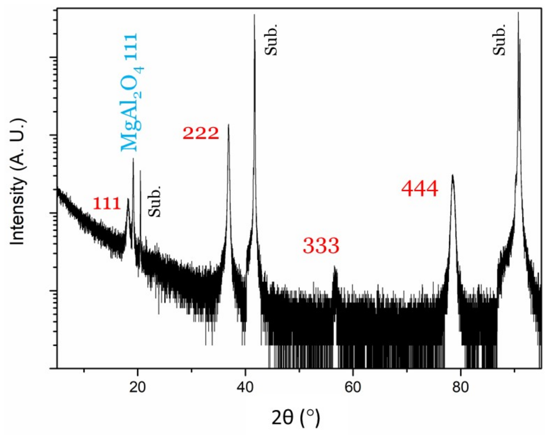
Figure 1. (a) XRD of as-deposited (Ti0.5, Mg0.5)N thin film showing growth in the (111) direction; (b) Pole figure measurements (inset) show twin-domain epitaxial growth.
Coatings 11 00089 g001
Figure 2. XRD comparison between as-deposited (Ti0.5, Mg0.5)N film with post-annealed films (30 min duration). At 820 °C, phase transformation becomes evident.
Coatings 11 00089 g002
Figure 3. XRD of post-annealed (Ti0.5, Mg0.5)N thin film (60 min duration). The results show the evolution of new peaks pointing towards a phase transformation and includes a reaction between the film and substrate (MgAl2O4 111).
Coatings 11 00089 g003
Figure 4. SEM comparison between as-deposited (Ti0.5, Mg0.5)N film with post-annealed films. The as-deposited films show a porous and columnar-type growth, while as the post-annealed films show a change in surface morphology hinting towards surface oxidation: (a) as-deposited; (b) annealed at 610 °C; (c) annealed at 770 °C; (d) annealed at 820 °C; (e) annealed at 820 °C for one hour.
Coatings 11 00089 g004
Figure 5. (a) High-resolution STEM image of newly formed nanoinclusions. Note that phase transformation occurs at grain boundaries; (b) SAED image of the nanoinclusion.
Coatings 11 00089 g005
Figure 6. XPS depth profile of the (Ti0.5, Mg0.5)N alloy film (annealed at 820 °C).
Coatings 11 00089 g006
Figure 7. EDS map of post-annealed film shows magnesium-rich and titanium-rich regions with phase transformation occurring in between.
Coatings 11 00089 g007
Figure 8. (a) 3D rendering of the LiTiO2-type stoichiometric TiMgN2 structure; (b) DFT band structure calculations predict that LiTiO2-type TiMgN2 has a direct bandgap of 0.07 eV.
Coatings 11 00089 g008
Table 1. Relationship between peaks of post-annealed (Ti0.5, Mg0.5)N thin film (60 min duration). Results show that the newly formed peaks are multiples of each other.
2θ (°)d-Spacing (Å)Multiple
18.254.861
36.882.441/2
56.751.621/3
78.531.221/4
Publisher’s Note: MDPI stays neutral with regard to jurisdictional claims in published maps and institutional affiliations.

