Article

Surface Modification of Aluminum 6061-O Alloy by Plasma Electrolytic Oxidation to Improve Corrosion Resistance Properties

by
Dmitry V. Dzhurinskiy
*,
Stanislav S. Dautov
,
Petr G. Shornikov
and
Iskander Sh. Akhatov
The Center for Design, Manufacturing and Materials, Skolkovo Institute of Science and Technology, Bolshoy Boulevard 30, bld. 1, 121205 Moscow, Russia
*
Author to whom correspondence should be addressed.
Coatings 2021, 11(1), 4; https://doi.org/10.3390/coatings11010004
Submission received: 25 November 2020 / Revised: 14 December 2020 / Accepted: 16 December 2020 / Published: 22 December 2020
(This article belongs to the Section Corrosion, Wear and Erosion)

Abstract

:
In the present investigation, the plasma electrolytic oxidation (PEO) process was employed to form aluminum oxide coating layers to enhance corrosion resistance properties of high-strength aluminum alloys. The formed protective coating layers were examined by means of scanning electron microscopy (SEM) and characterized by several electrochemical techniques, including open circuit potential (OCP), linear potentiodynamic polarization (LP) and electrochemical impedance spectroscopy (EIS). The results were reported in comparison with the bare 6061-O aluminum alloy to determine the corrosion performance of the coated 6061-O alloy. The PEO-treated aluminum alloy showed substantially higher corrosion resistance in comparison with the untreated substrate material. A relationship was found between the coating formation stage, process parameters and the thickness of the oxide-formed layers, which has a measurable influence on enhancing corrosion resistance properties. This study demonstrates promising results of utilizing PEO process to enhance corrosion resistance properties of high-strength aluminum alloys and could be recommended as a method used in industrial applications.

1. Introduction

Aluminum-based alloys have received increasing attention due to their advantages of high strength to weight ratio and proper corrosion resistance. Corrosion resistance of aluminum is excellent under many corrosive conditions, for instance unalloyed aluminum performs better than other coated metals. High-strength 6xxx series aluminum alloys are usually used in aircraft, defense, automotive and marine areas of industrial applications [1]. Nevertheless, high-strength aluminum alloys where the precipitation hardening phenomena can increase mechanical properties can be affected by different corrosion forms [2,3,4,5]. Among others, AA6061 (AD-33) alloy possesses the intermetallic for example, CuAl2, Mg2Si, MgZn2 compounds, to drive a precipitation hardening [1]. The metal oxidation being initiated by cathodic—anodic actions to the aluminum alloy base, where corrosion primarily occurs and progresses at the phases surface interfaces. Whereas new and better high-strength 6xxx series alloys are continuously developed, the presence of intermetallic compounds makes it susceptible to the attack of localized corrosion. Most severely, high-strength aluminum alloys are vulnerable to pitting and stress-assisted corrosion where the variation from spot to spot may be enormous [6,7]. At least three forms of attack on aluminum alloys are particularly serious under Federal Aviation Administration Advisory Circular corrosion control: (1) the penetrating pit-type corrosion through the aluminum walls, (2) stress corrosion involving cracking of materials under sustained stress and (3) intergranular corrosion, characteristic of particular improperly heat-treated aluminum alloys.
Protective coatings must be used to preserve aluminum alloys from different corrosion forms. The primary coating layers function being to isolate structural reactive elements from environmental corrosives, therefore any factor that tends to improve the insulating ability of the protective coating enhances the corrosion resistance of aluminum alloys [8]. Commonly used hard anodizing of aluminum alloys with high Mg-, Si- and Cu-content represents a considerable challenge specify a thin anodized layer tends to be highly porous [9]. Among other standard conventional protection methods for high-strength aluminum alloys, such as cladding, priming and cold spraying [8,9,10], there was recent attention given to emerging Plasma Electrolytic Oxidation (PEO) technology. PEO is considered an environmentally-friendly process that offers versatility in coating most aluminum alloys, including Mg-, Si- and Cu-containing alloys and aluminum-based metal matrix composites [11]. Nowadays, with the development of a state of the art power supply systems and environmental requirements addressed to anodizing technology, PEO technology has been attracting a lot of attention with a promising potential in different industrial applications [12].
The PEO process is based on the plasma-assisted electrochemical conversion of a metal surface into an oxide ceramic layer. Therefore, it provides several advantages and offers a dense fused structure of the oxide coating with excellent corrosion performance over superior commercial chromate conversion coatings [13]. Moreover, by adjusting process parameters, there is the possibility of precisely controlling the coating layer thickness and surface morphology, consequently forming coatings on complex shapes with a higher growth rate than conventional anodizing methods. Therefore, PEO-based surface engineering is a promising process for creating corrosion protection coatings not only on aluminum but also on magnesium-, titanium- and zirconium-based alloy substrates, including hybrid coatings [14,15].
Typically, PEO treatment for aluminum-based alloys is carried out in alkaline solutions containing metasilicate anions, which is environmentally-friendly and most widely used in research and industrial applications. Commonly, alkaline solutions containing metasilicate poses development of exceptionally foamy- like coating structure of PEO treated materials where it is hard to expect superior behavior in corrosion environment [14]. Though, it has been established that the addition of Na2SiF6 affects the surface roughness, where diameters of the discharging channels decrease and promote the formation of a dense coating layer [16]. The fluoride ions are characterized to exhibit a complex behavior with a wide interval of passivation [17], therefore providing the ability to control the PEO’s coating layer densification process by dispersing the Aluminum Fluoride phase formation [18]. Despite the fact that Na2SiF6 effectively enhanced the growth ability and densification of the ceramic layers during the PEO process, it is a well-known fact that sodium hexafluorosilicate and sodium fluorosilicate are hazardous products for human health and the aquatic environment due to its ionizing fluorine. In cases of decomposition, it releases toxic hydrogen fluoride. It is also essential to remember that when aluminum comes in contact with water, the corresponding metal hydroxide and hydrogen are formed. Such a reaction only proceeds with aluminum in the presence of alkaline compounds, such as NaOH or KOH. The type of alkali solution typically acts as a catalyst in the production reaction of metal hydroxide and hydrogen evolution. NaOH commonly promotes faster responses and higher real yields of metal hydroxides than KOH. On the other hand, NaOH leads to the generation of foamy-like structures during the PEO process, leading to the degradation of corrosion protection properties.
In recent years, the effect of power mode—including frequency, duty cycle and current density has gained a lot of attention as critical processing parameters affecting corrosion behavior of PEO coating layers [19]. A substantial amount of published papers on PEO coatings on aluminum report how the process parameters affect the physical, mechanical and tribological properties [20,21,22,23]. However, there are limited systematic attempts to analyze PEO coating layers related to corrosion resistance or identify the best treatment parameters and electrolyte composition to confirm the best carrion protection properties.
In this work, the PEO technique has been employed to form protection coatings intending to promote corrosion resistance properties of high-strength aluminum alloy. This study evaluates the coating layer structural features and attempts to understand the corrosion resistance behavior of PEO-treated 6061-O aluminum alloy by analyzing the electrochemical properties. Moreover, given the processing parameters and electrolyte composition, the present study attempts to find the optimum combination of technological parameters to achieve dense coating layers, ensuring the best corrosion resistance.

2. Materials and Methods

2.1. Materials

The substrate material selected in the present investigation was the 6061-O aluminum alloy with a nominal chemical composition presented in Table 1. All specimens used in this study and subject to PEO treatment were in the rectangular shape of 23 mm × 60 mm and 1 mm thickness with a total treated area of 2900 mm2.

2.2. Coatings Preparation and Process Parameters

Prior to PEO treatment, the main sample surfaces of 6061-O aluminum alloy were ground using #800 abrasive paper and cleaned with ethyl alcohol, rinsed with distilled water and dried. The samples were PEO-treated in 5 L of electrolyte solution containing 5 g·L−1 sodium metasilicate pentahydrate (Na2SiO3∙5H2O) and 2 g·L−1 potassium hydroxide (KOH), with specific attention given to maintaining the electrolyte temperature at about 23 °C during PEO treatment time. The conductivity of the prepared solution was measured at 19.5 mS·cm−1. In this study, a unipolar two-stage current regime has been used. At the first stage, a potentiostatic polarization at U(+) = 200 VDC was applied for 15 s enabling the formation of uniform primary oxide film on the surface of aluminum alloy, this was followed by galvanostatic polarization using unipolar current mode at the current density of i(+) equal to 5.16 A·dm−2. It is worth mentioning that to improve the sealing characteristics, the applied i(+) current was gradually reduced during the last minute of the treatment process, ensuring a change of the current mode from unipolar to the soft-sparking unipolar regime. The main PEO process parameters and sample designation are presented in Table 2.

2.3. Coatings Characterization Methods

The corrosion resistance of PEO-treated and bare 6061-O aluminum alloy substrates was evaluated by employing electrochemical measurements in the N2 aerated 1 M NaCl test solution. The electrochemical behavior of the specimens was examined using galvanostat/potentiostat Biologic SP-150 system with a typical three-electrode cell consisting of (1) the studied sample with an exposed surface area of 3 cm2 as the working electrode, (2) a graphite rod as the counter electrode and (3) the Ag/AgCl (3.5 M KCl) as the reference electrode. The following techniques were employed in this study: (i) Open circuit potential (OCP) measurements. OCP test was performed during the immersion test, where the samples were suspended in the test solution and the potential was recorded every 30 s over the period of 2 h. (ii) DC polarization tests were implemented after 1 h of rest potential under open-circuit conditions (working electrode is not polarized). The DC linear polarization measurements consisted of sample polarization from the cathodic potential of −250 mV vs. OCP to the highest potential of +1000 mV vs. OCP at a constant sweep rate dE/dt equal to 1 mV·s−1. Within this range of potentials and depending on the quality of the surface oxide film, it is determined whether a material exhibits passive behavior. Tafel extrapolation, as a mathematical technique, was used to determine the values of corrosion current density and corrosion potential. (iii) The surface oxide layer behavior was also studied by electrochemical impedance spectroscopy (EIS). Experiments were carried out by an AC amplitude of 10 mV around OCP over the frequency range of 0.1–105 Hz. The impedance behavior of a corrosion system was expressed in Bode plots of impedance modulus |Z|, phase angle ψ as a function of frequency and in complex plots of Z″ (ω) as a function of Z’(ω), where ω is the angular frequency of the perturbation. The data were collected and analyzed using build-in analysis tools available at EC-Lab software (veriosn 11.33).
Coating thickness was measured utilizing eddy current probe, as averaged by 5 measurements and later confirmed by image analysis of cross-sectional planes. Special precautions have been taken to ensure that the coating layer is not affected by the sample cross-section preparation procedure. Microstructure and surface morphology characterization of PEO-treated coatings was performed by field emission scanning electron microscopy according to ASTM E1588 [24] using ThermoScientific Quattro ESEM (Waltham, MA, USA) with Bruker XFlash6160 (Billerica, MA, USA).

3. Results and Discussion

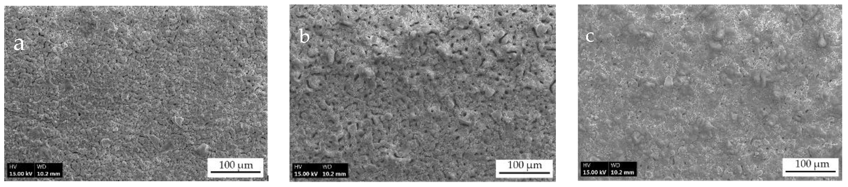
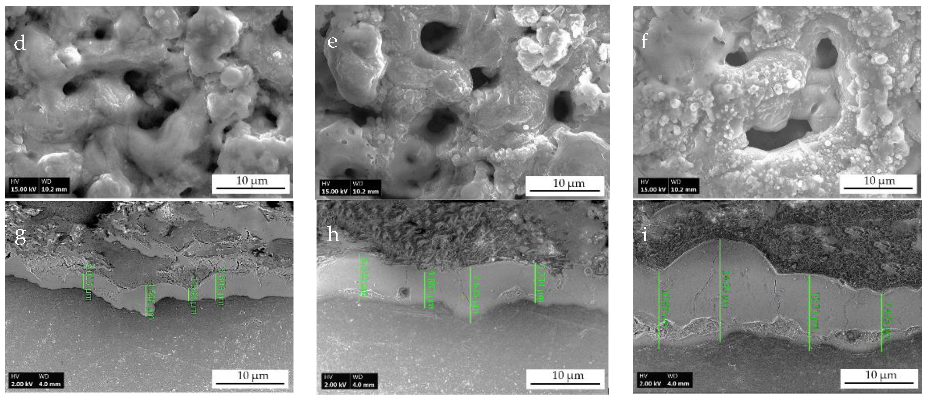
3.1. Visual Surface Appearance and Microstructure Characteristic Features

Figure 1 shows typical SEM microphotographs of the surface morphology of PEO-treated specimens. The presence of many small holes/cracks/pores with an average pore size ranging from 0.5 to 4 μm corresponded to plasma discharge channels, as depicted in Figure 1d–f. Shrinkage cracks of larger pancake-shaped particles are not visible from the surfaces. Thereby a uniformly distributed porous structure with a relatively smooth surrounding area near the pores poses a characteristic of the dense oxide layers grown by PEO processes utilizing the unipolar DC electrical mode [17]. The intensity of the surface pores depends on the PEO treatment parameters, coating roughness and the pores size diameters increasing with a greater current density of applied potential, similar to Chiesa’s findings [25]. Figure 1 shows that the pore shape was mostly round and most pores were found to be not connected.
Typical cross-sectional images of the formed coatings subject to evaluation in this study are depicted in Figure 1g–i. It can be seen that the coating thickness is about 4 microns for AA-4 and 8 µm of AA-8, whereas this reaches 12 µm for AA-12 with a highly dense structure. The evolution of micro-cracks and micropores distributed through the coating layer is clearly observed suggesting that the PEO treatment time plays a critical role in the formation of dense oxide layers. Also, as can be observed, the micropores formed at the substrate interface caused by gas bubbles at the micro-discharge channels Figure 1i, suggesting a presence of the voltage threshold. The dense oxide layer integrated firmly into the aluminum substrate should be considered as the main feature enhancing the corrosion resistance properties of PEO-treated 6061-O aluminum alloy. This fact was reported previously in the other studies, whereas the interface between the oxide layer and the aluminum substrate does not have any discontinuity [26]. This is a reference to a viewpoint discussed and supported by the electrochemical tests described below.

3.2. Electrochemical Properties

The electrochemical properties of the oxide layer and its response to the environment play an important role during product lifecycle and ensure resource-efficient corrosion protection. The environment to which aluminum-based materials and products are exposed during prolonged use can be described as an aqueous medium containing various anions, cations, organic substances and dissolved oxygen. The presence of chloride ions in the electrolyte has an aggressive effect on the durability of passive films formed on the aluminum surface [1]. Additionally, chloride ions usually cause localized corrosion by generating pits on the surface. Therefore, N2 aerated 1 M NaCl test solution has been chosen in this study to characterize PEO-treated 6061-O aluminum alloy by several electrochemical testing techniques in comparison to the bare 6061-O aluminum.

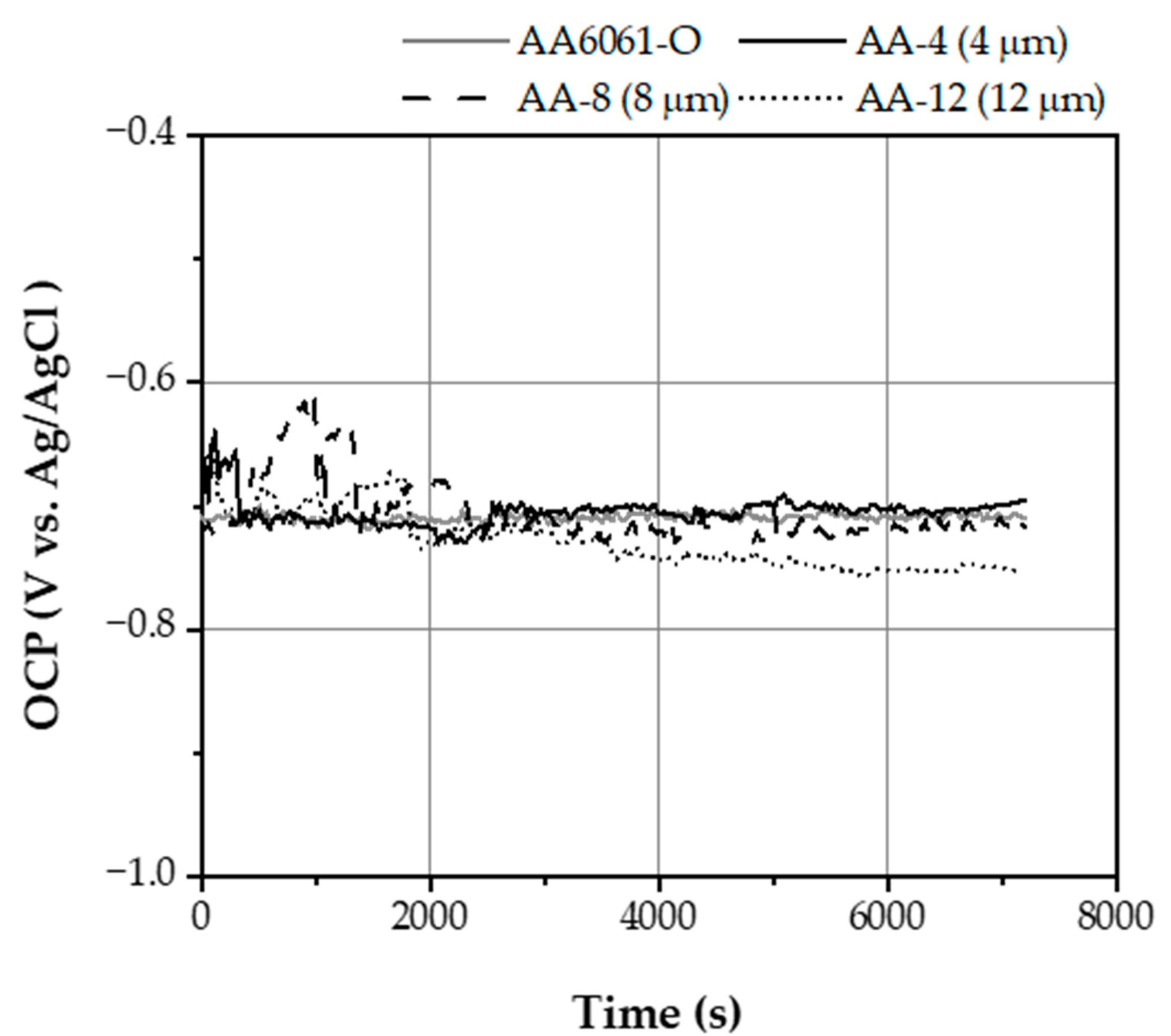
3.2.1. Open Circuit Potential Behavior

Open circuit potential (OCP) measurements were used to evaluate the corrosion behavior of all studied specimens and indicate a thermodynamic tendency of material toward electrochemical dissolution/passivation in a corrosive medium. Figure 2 shows the evolution of the OCP for the tested specimens immersed in a test solution for 120 min at room temperature.
It can be seen that the potential of the bare 6062-O aluminum alloy over the test period remains constant at −710 mV with a sign of a passive film presence at the material surface. This type of behavior indicates that the aluminum-based alloy being immersed into the electrolyte tends to form a protective oxide layer on its surface. The OCP value of AA-4 and AA-8 specimens, with the oxide film thickness of 4 and 8 µm, respectively, exhibit potential stabilization around −700 mV after 60 min of immersion, pointing to the formation of stable double layer conditions at the coating surface. These values can be attributed to the formation of the enhanced passive oxide film by the PEO process. Thus, the obtained results from open circuit potential monitoring suggest that the coating of 4 and 8 µm oxide film thicknesses produced by the PEO process is dense and has similar corrosion behavior compared to the bare 6061-O alloy immersed in 1 M NaCl test solution. However, a shift was observed in OCP to negative values and stabilized at around −750 mV for AA-12 coated specimen, where the coating thickness richness of 12 µm. Hence, it may indicate an increase in the driving force for the corrosion process at the coating interface. Therefore, suggesting that the thermodynamic tendency of corrosion is increased. It is possible that electrical charges accumulate locally and the electrons become trapped at the oxide film defects Figure 1i. These findings demonstrate that the corrosion behavior of the examined PEO coatings depends on the coating thickness and structure.
Another observation made from the OCP analysis is a data noise caused by potential oscillation behavior. The oscillation amplitude, after 90 min of exposure to the test solution, was found to be approximately 9 mV for the bare 6061-O alloy; that of AA-4 about 10 and 28 mV were obtained for the AA-8 coating, while AA-12 showed 11 mV in potential oscillation. It is considered that the magnitude of the oscillation depends on the surface roughness that results in the changing of an oxide layer through the progression of PEO treatment time. This feature is attributed to and associated with activation—repassivation process during the formation of new interfaces at the surface/coating boundary, similar to previously reported findings [27]. Another possible reason for such behavior is that the surface roughness promotes effective nucleation and propagation of metastable and stable diffusion paths inside the coating since ionic conduction predominantly occurs through the loose coating layer. A more detailed investigation of this effect should be made in future work, whereas adsorption effects of electrolyte’ ions at the coating surface must be considered in detail.

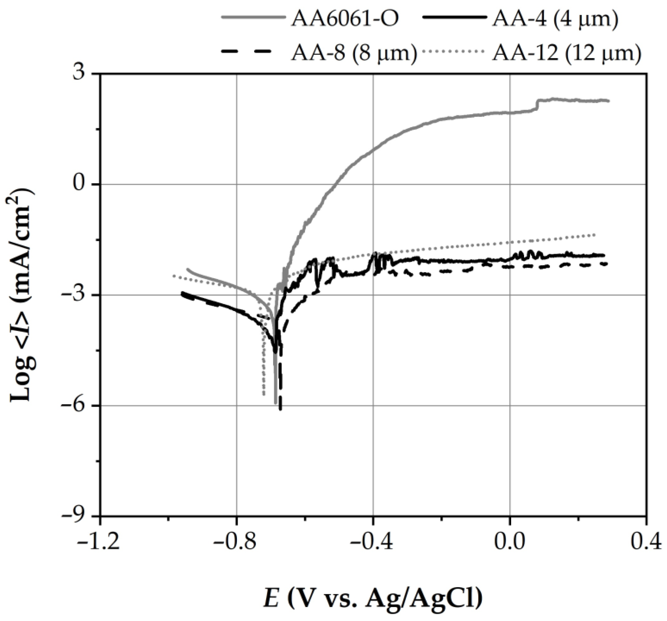
3.2.2. Potentiodynamic Polarization Behavior

Linear potentiodynamic DC polarization testing (LP) was conducted to understand further corrosion properties and behavior of the bare 6061-O alloy in the uncoated condition and with the PEO coatings. After an equilibration period of 60 min at an open circuit, a linear DC potentiodynamic scan was initiated at a pre-determined scan rate. The total system potential is recorded throughout the scan and the potential vs. log current density data is plotted and analyzed by Tafel fit method. The collected data of potentiodynamic polarization curves are summarized and depicted in Figure 3, where the breakdown potential “Eb” along with the corrosion potential “Ecorr” and current “Icorr” values were used to compare the corrosion behavior and assess protection properties. At the same time, the results are compiled in Table 3.
Analysis of results comparison shows the effect of the corrosion potential (Ecorr) decreases with an increase of coating thicknesses and roughness, whereas a corrosion potential did not show many differences with OCP values. This is mainly due to the low scanning rate employed in this study. The Ecorr is poised at −670 mV for the bare 6061-O alloy, whereas it is around −680 mV for the AA-4 and AA-8 coatings, in agreement with previously reported data [3,28]. For the AA-12 coating layer with a thickness of 12 µm, the corrosion potential starts to decrease and is controlled at −720 mV. This behavior is intimately associated with the resulting coating microstructure array (Figure 1g–i) in the course of the applied PEO process parameters route, suggesting optimization in PEO treatment time.
Despite the fact that more negative corrosion potential represents greater susceptibility to corrosion attack, there is a need to consider changes in corrosion current (Icorr) while assessing corrosion resistance in totality. Significantly measurable differences in the corrosion current were observed for all specimens involved during corrosion tests. It was previously reported [29] that, during linear polarization and in the presence of chloride ions within the test solution, anodic current induces localized rupture of aluminum protection oxide film and promotes the formation of the corrosion product in the form of aluminum chloride film. In the present study, similar behavior was found in the case of the bare 6061-O alloy, whereas PEO treated AA-4 specimen shows a significant decrease of Icorr over the polarization interval. This is characteristic of a more passivated system. The other key characteristic of protection behavior against corrosion is a breakdown potential (Eb), while the closer Eb is to Ecorr, the greater the probability is of localized pitting take place. The polarization curves of all examined specimens exhibit thermodynamic quantities, with Eb values of −660 mV for the bare 6061-O alloy, where the current rapidly increases over the rise of polarization potential, indicating a threshold of rapid corrosion rate. Furthermore, the presence of another breakdown potential at 100 mV for the bare 6061-O alloy suggests intensive pitting formation caused by damage of the passive layer.
On the other hand, for all PEO-treated 6061-O alloy specimens, a stable, protective passive film was formed on the aluminum alloy surface. The presence of a constant current region and a more positive value of breakdown potential indicates improved resistance to corrosion attack. Nevertheless, there were spikes observed in anodic current over the polarization of the AA-4 specimen, which clearly indicates a lack of dense and compact oxide film formation during PEO treatment. This variation in anodic current density indicates semi-passivation actions, where the corrosion products are filling up the pores and cracks within the protective layer, alike to previously reported studies [30]. Thereby, the corrosion protection efficiency during the linear polarization study was found to be different for all investigated specimens, where AA-8 exhibits improved properties out of all tested specimens.

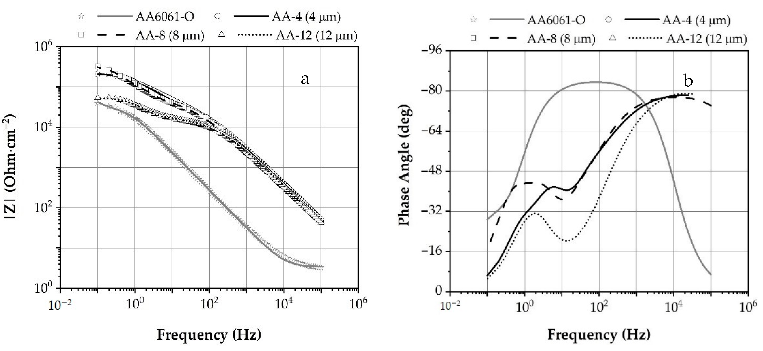
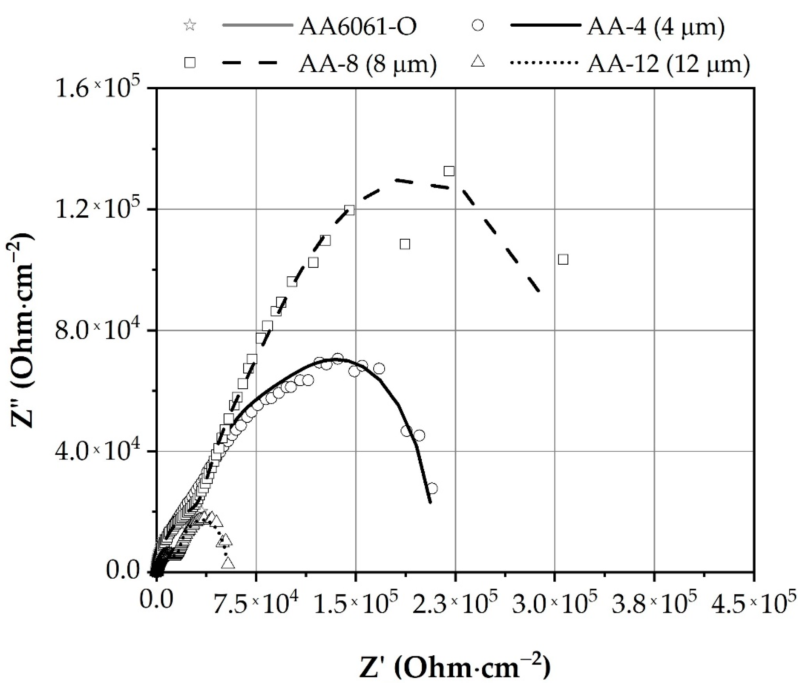
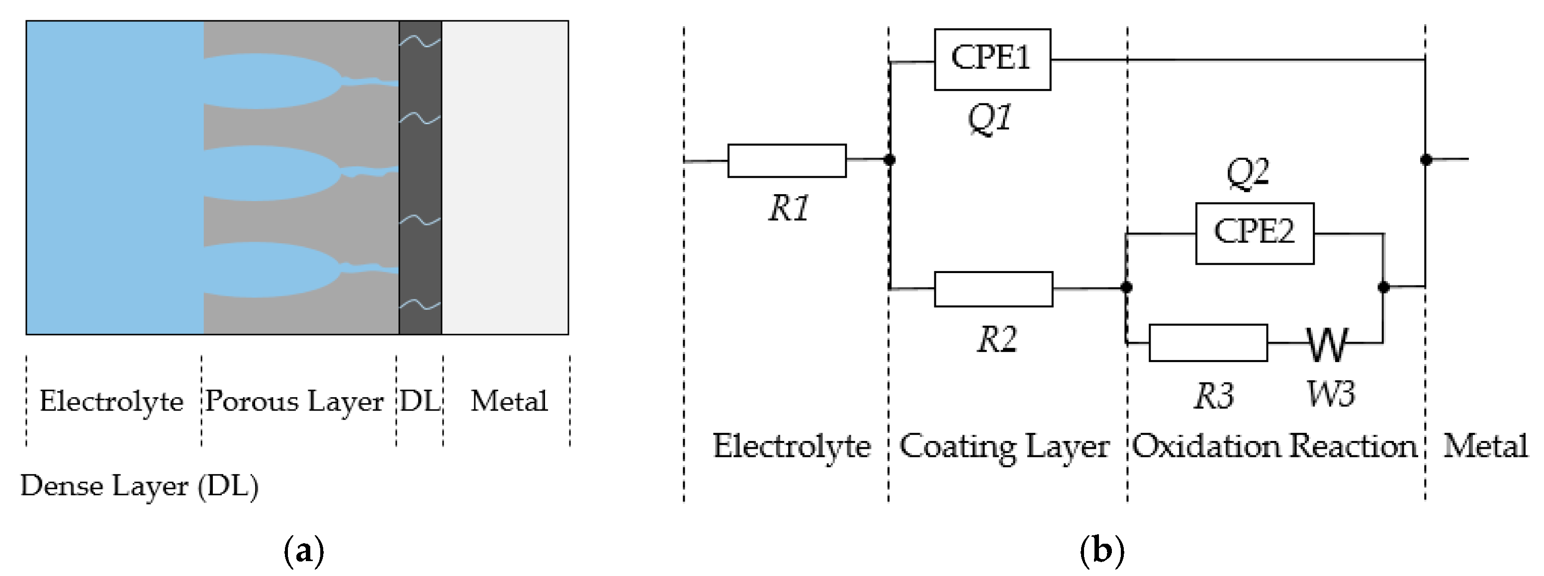
3.2.3. Electrochemical Impedance Spectroscopy

Electrochemical impedance spectroscopy (EIS) analysis was carried out in addition to linear DC polarization studies to attain a more detailed examination of the corrosion susceptibility and protection properties of PEO-formed coatings. The characteristic EIS spectra of the specimens investigated in the present study are presented in Figure 4 and Figure 5. The bare 6061-O alloy exhibited much lower impedance magnitude in the high-frequency domain (>102 Hz) compared with the PEO-treated 6061-O alloy, regardless of the coating thicknesses when considering the fact that the high-frequency impedance usually reflects the resistance of the coating [31]. Similar behavior was found in the low-frequency region (0.1–1 Hz), where the AA-8 specimen presented a higher impedance modulus in comparison to other investigated specimens and the phase shift at high frequency is due to the capacitive properties of the PEO-formed coatings (Figure 4b). On the other hand, as observed, the impedance at the low-frequency region represents the corrosion resistance of the coatings (Figure 4a). By comparing the EIS spectra of each tested specimen, it could be concluded that the PEO treatment has a significant effect in improving susceptibility to corrosion of aluminum alloys. As previously confirmed, the protection ability of the AA-8 coating deteriorated in line with an increase of PEO treatment time. However, it is best in comparison to AA-4 and AA-12.
The kinetic processes involved during the electrochemical impedance test remained the same for all coated specimens in the test solution, as reflected by its impedance spectra (Figure 5). For example, the complex plots featured one depressed semi-circle associated with the dispersive capacitive behavior of the PEO coatings in the high-frequency region, followed by a diffusional process in the low-frequency region. Such impedance spectra behavior suggested that two kinetic processes with different time constants were involved during the immersion of the PEO-coated sample. The first indicated semi-passivation actions, where the corrosion products find a diffusion path inside the PEO coating by filling up the pores and cracks, similarly to the above reported finding during an analysis of OCP and linear polarization results. The second stage is associated with the repassivation process through the loose coating layer. This feature is not associated with a typical resistive-capacitive (R-C) behavior, featuring almost constant phase angle, whereas a change of a phase angle over a wide frequency range (0.1–100 Hz) (Figure 4b) suggests the presence of cracks within a stable passive film on the sample surface. Furthermore, in the low-frequency range (<10 Hz), a diffusional tail became apparent, which might be attributed to the possible precipitation of corrosion compounds inside coating cracks, thereby sealing the cracks. Such an observation is consistent with the OCP measurements behavior for all tested specimens where two kinetic processes are driven, as proposed.
The R-C behavior was noticeable in the high to medium frequency range (102–104), as shown by a depressed semi-circle in its complex plot (Figure 5). The equivalent circuit where the polarization is due to a combination of kinetic and diffusion processes was proposed to model and analyze the collected EIS spectra and depicted in Figure 6.
In this equivalent circuit, R1 and R2 represented the solution and coating layer resistances, respectively. Q1 is the electric capacity (CPE1) responsible for imperfect dielectric coating layer behavior, in series with a parallel combination of the charge transfer resistance R3 and capacitance Q2 (CPE2) of the double layer (these control the reaction rate from the kinetic point of view) and in series additional Warburg element (W3) as the characteristic constant from the diffusion impedance expression. This parameter controls the reaction rate through the influence of the diffusion of oxidizing and reducing species to and from the metal substrate. It should also be mentioned here that the diffusional elements could be verified by the associated Bode plots, where the phase angles in the low frequency deviated from the theoretical value of −45° for the ideal Warburg element. This might result from a non-linear diffusion process originating from the non-ideal geometry of the diffusion layers inside PEO-formed coating [32].
The element values, in accordance with the designed circuits (Figure 6) used to fit the EIS data, are listed in Table 3. In addition, the fitting results are presented in Figure 4 and Figure 5 by the solid lines. Analysis of the equivalent circuit values demonstrates a variation in R1 solution resistance, suggesting the difference in coating morphology and therefore associated with changing electrolyte reactivity towards surface charge and double layer formation. The chi-square values (χ2) on the orders of 10−3 to 10−2 indicate sufficient fitting goodness of the proposed model and experimental values.
Considering the total resistance (Rtotal) of all investigated specimens as a sum of coating layer resistances R2 and charge transfer resistance R3, it could be concluded that the PEO coating provides corrosion protection (Table 4). However, total resistance deteriorated significantly for AA-12 coating; this is possibly due to the formation of larger layer defect passages filled with the test solution of low resistance, indicating a decrease in corrosion protection properties.
Analysis of EIS experimental data and results of the proposed equivalent circuit modeling confirms previously discussed findings and suggests diffusion-precipitation of amorphous corrosion product phases as a mechanism of coating micro-sized defects sealing, mainly responsible for corrosion protection stability of PEO coatings. The PEO coating thickness of 8 µm is found to fit the best in resistance to corrosion.

4. Conclusions

This study demonstrates the effectiveness of Plasma Electrolytic Oxidation surface treatment in producing coating layers intended to enhance corrosion-protection properties of high-strength aluminum alloys, where the KOH is suggested as a solution for coating densification. Though it has been determined that KOH results in a low coating growth rate, continued work should be conducted to increase the coating growth rate, for instance, the addition of NaAl(OH)4 to the alkaline silicate electrolyte could be considered as the compound to replace NaOH by NaAlO2.
In conformity to potentiodynamic polarization and EIS test findings, the repassivation process at the coating defects, accompanied by diffusion-precipitation of amorphous corrosion product phases due to soft-sparking unipolar regime and proposed as a mechanism of coating micro-sized defects sealing, mainly responsible for the stability against localized corrosion.
As reported, the coating thickness of 8 µm possesses higher resistance in respect to all tested specimens in the present study and is recommended to provide an effective barrier against corrosion attacks in chloride environments. Nonetheless, there is a need to answer the questions related to susceptibility to hydrogen embrittlement and long-term corrosion behavior.

Author Contributions

Conceptualization, D.V.D. and I.S.A.; methodology, D.V.D.; formal analysis, D.V.D.; data curation, P.G.S.; writing—original draft, D.V.D. and S.S.D.; writing—review and editing, D.V.D.; visualization, D.V.D. and P.G.S.; supervision, D.V.D. and I.S.A. All authors have read and agreed to the published version of the manuscript.

Funding

This research received no external funding.

Data Availability Statement

Data is contained within the article.

Conflicts of Interest

The authors declare no conflict of interest.

References

  1. ASM Handbook Properties and Selection: Nonferrous Alloys and Special-purpose Materials. ASM International Committee Handbook, 2nd ed.; ASM International: Materials Park, OH, USA, 1990. [Google Scholar]
  2. Buchheit, R.G.; Grant, R.P.; Hlava, P.F.; McKenzie, B.; Zender, G.L. Local dissolution phenomena associated with s-phase (Al2CuMg) particles in aluminum alloy. J. Electrochem. Soc. 1997, 144, 2621–2628. [Google Scholar] [CrossRef]
  3. Guillaumin, V.; Mankowski, G. Localized corrosion of AA 2024 T351 aluminum alloy in chloride media. Corros. Sci. 1998, 41, 421–438. [Google Scholar] [CrossRef]
  4. Blanc, C.; Gastaud, S.; Mankowski, G. Mechanistic studies of the corrosion of 2024 aluminum alloy in nitrate solutions. J. Electrochem. Soc. 2003, 150, 396–404. [Google Scholar] [CrossRef]
  5. Ilevbare, G.O.; Schneider, O.; Kelly, R.G.; Scully, J.R. In Situ confocal laser scanning microscopy of AA 2024-T3 corrosion metrology I: Localized corrosion of particles. J. Electrochem. Soc. 2004, 151, 453–464. [Google Scholar] [CrossRef]
  6. Buchheit, R.G.; Montes, L.P.; Martinez, M.A.; Hlava, P.F. The electrochemical characteristics of bulk-synthesized materials. J. Electrochem. Soc. 1999, 146, 4424–4428. [Google Scholar] [CrossRef]
  7. Andreatta, F.; Terryn, H.; Wit, J.H.W. Corrosion behaviour of different tempers of aluminium alloy. Electrochim. Acta 2004, 49, 2851–2862. [Google Scholar] [CrossRef]
  8. Cerchier, P.; Pezzato, L.; Gennari, C.; Moschin, E.; Moro, I.; Dabala, M. PEO coating containing copper: A promising anticorrosive and antifouling coating for seawater application of AA 7075. Surf. Coat. Technol. 2020, 393, 125774. [Google Scholar] [CrossRef]
  9. Csokan, P.; Sc, C.C. Hard anodizing: Studies of the relation between anodizing conditions and the growth and properties of hard anodic oxide coatings. Electroplat. Met. Finish. 1962, 15, 75–82. [Google Scholar]
  10. Dzhurinskiy, D.; Maeva, E.; Leshchinsky, E. Corrosion protection of light alloys using low pressure cold spray. J. Term. Spray Technol. 2012, 21, 304–313. [Google Scholar] [CrossRef]
  11. Zhang, P.; Nie, X.; Hu, H. Wear protection of Al383/SiO2 metal matrix composites by plasma electrolytic oxidation (PEO) process. SAE Int. J. Mater. Manuf. 2010, 3, 55–62. [Google Scholar] [CrossRef]
  12. MAGPULS Bipolar-Pulsed Power Supplies. Available online: https://magpuls.de/en/puls-plasma-generators-unipolar.html (accessed on 1 November 2020).
  13. Richelly, L.N.; Ferreira, M.; Clodomiro, A. Plasma species and coating compositions in aluminum treated by PEO using shot square pulse. Mater. Res. 2020, 23. [Google Scholar] [CrossRef]
  14. Clyne, T.W.; Troughton, S.C. A review of recent work on discharge characteristics during plasma electrolytic oxidation of various metals. Int. Mater. Rev. 2019, 64, 127–162. [Google Scholar] [CrossRef] [Green Version]
  15. Pezzato, L.; Cerchier, P.; Brunelli, K.; Bartolozzi, A.; Bertani, R.; Dabala, M. Electrolytic oxidation coatings with fungicidal properties. Surf. Eng. 2018, 35, 325–333. [Google Scholar] [CrossRef]
  16. Wang, K.; Koo, B.-H.; Lee, C.-G.; Kim, Y.-J.; Lee, S.-H.; Byon, E. Effects of electrolytes variation on formation of oxide layers of 6061 Al alloys by plasma electrolytic oxidation. Trans. Nonferrous Met. Soc. China 2009, 19, 866–870. [Google Scholar] [CrossRef]
  17. Yerokhin, A.; Nie, X.; Leyland, A.; Matthews, A.; Dowey, S. Plasma electrolysis for surface engineering. Surf. Coat. Technol. 1999, 122, 73–93. [Google Scholar] [CrossRef]
  18. Gnedenkov, S.; Khrisanfova, O.; Zavidnaya, A.; Sinebrukhov, S.; Kovryanov, A.; Scorobogatova, T.; Gordienko, P. Production of hard and heat-resistant coatings on aluminium using a plasma micro-discharge. Surf. Coat. Technol. 2000, 123, 24–28. [Google Scholar] [CrossRef]
  19. Dehnavi, V.; Luan, B.L.; Liu, X.Y.; Shoesmith, D.W.; Rohani, S. Correlation between plasma electrolytic oxidation treatment stages and coating microstructure on aluminum. Surf. Coat. Technol. 2015, 269, 91–99. [Google Scholar] [CrossRef]
  20. Gulden, F.; Reinhold, B.; Gramstat, S.; Stich, A.; Tetzlaff, U.; Höppel, H.W. Investigation of the run-in and corrosion behavior of a PEO-coated aluminum brake disc. In Proceedings of the 10th International Munich Chassis Symposium 2019, Wiesbaden, Germany, 2 November 2019. [Google Scholar]
  21. Patel, V.K.; Bhowmik, S. Plasma processing of aluminum alloys to promote adhesion: A critical review. Rev. Adhes. Adhes. 2017, 5, 79–104. [Google Scholar] [CrossRef]
  22. Curran, J.A.; Clyne, T.W. Thermo-physical properties of plasma electrolytic oxide coatings on aluminium. Surf. Coat. Technol. 2005, 199, 168–176. [Google Scholar] [CrossRef]
  23. Dahm, K.; Black, A.; Shrestha, S. Dearnley, plasma electrolytic oxidation treatment of aluminium alloys for lightweight disc brake rotors. In Proceedings of the IMechE Conference on Braking, New York, NY, USA, 9–10 June 2009; pp. 53–60. [Google Scholar]
  24. ASTM E1588-20, Standard Practice for Gunshot Residue Analysis by Scanning Electron Microscopy/Energy Dispersive X-ray Spectrometry; ASTM International: West Conshohocken, PA, USA, 2020.
  25. Chiesa, R.; Sandrini, E.; Santin, M.; Rondelli, G.; Cigada, A. Osseointegration of titanium and its alloys by anodic spark deposition and other electrochemical techniques: A review. J. Appl. Biomater. 2003, 1, 91–107. [Google Scholar]
  26. Dicu, M.; Abrudeanu, M.; Millet, J.; Moga, S.; Rizea, V.; Ducu, C. The influence of electrochemistry parameters on some physico-chemical properties of microarc oxidation biocompatible coatings on titanium. Sci. Bull. 2012, 74, 193–202. [Google Scholar]
  27. Ye, Z.; Liu, D.; Zhang, X.; Wu, Z.; Long, F. Influence of combined shot peening and PEO treatment on corrosion fatigue behavior of 7A85 aluminum alloy. Appl. Surf. Sci. 2019, 486, 72–79. [Google Scholar] [CrossRef]
  28. DeForce, B.; Eden, T.; Potter, J.; Champagne, V.; Leyman, P.; Helfritch, D. Application of aluminum coatings for the corrosion, protection of magnesium by cold spray. In Proceedings of theTri-Service Corrosion Conference, Denver, DC, USA, 17–21 November 2007. [Google Scholar]
  29. Curioni, M.; Scenini, F. The mechanism of hydrogen evolution during anodic polarization of aluminium. Electrochim. Acta 2015, 180, 712–721. [Google Scholar] [CrossRef]
  30. Kaseem, M.; Yang, H.W.; Ko, Y.G. Toward a nearly defect-free coating via high-energy plasma sparks. Sci. Rep. 2017, 7, 2378. [Google Scholar] [CrossRef] [PubMed]
  31. Ryu, H.S.; Mun, S.-J.; Lim, T.S.; Kim, H.-C.; Shin, K.-S.; Hong, S.-H.; Tanasini, P.; Diethelm, S.; Van Herle, J.; Favrat, D.; et al. Microstructure evolution during plasma electrolytic oxidation and its effects on the electrochemical properties of AZ91D Mg alloy. J. Electrochem. Soc. 2011, 158, 266–273. [Google Scholar] [CrossRef]
  32. Macdonald, D. Reflections on the history of electrochemical impedance spectroscopy. Electrochim. Acta 2006, 51, 1376–1388. [Google Scholar] [CrossRef]
Figure 1. Surface morphology views and cross-sectional scanning electron microscopy images of the PEO coating formed at different process parameters: AA-4 (a,d,g); AA-8 (b,e,h); AA-12 (c,f,i).
Coatings 11 00004 g001aCoatings 11 00004 g001b
Figure 2. Evolution of the open circuit potential for the investigated samples as a function of immersion time in corrosive media.
Coatings 11 00004 g002
Figure 3. Potentiodynamic DC linear polarization curves of all tested specimens in 1 M NaCl corrosive media.
Coatings 11 00004 g003
Figure 4. Experimental electrochemical Bode impedance spectra of investigated specimens tested in N2 aerated 1 M NaCl test solution (a) Complex plane plots; (b) Phase angle vs. log frequency and impedance behavior vs. log frequency plots.10−2.
Coatings 11 00004 g004
Figure 5. Experimental electrochemical Nyquist impedance spectra in the complex plane.
Coatings 11 00004 g005
Figure 6. Schematic illustration (a) and equivalent circuit (b) representation with mixed kinetic and charge-transfer control used to model the electrochemical impedance spectroscopy (EIS) spectra of PEO-coated specimens.
Coatings 11 00004 g006
Table 1. Chemical composition of the 6061-O aluminum alloy (wt.%).
AlSiFeCuMnMgCrZnTi
balance0.40–0.80Max 0.700.15–0.400.150.80–1.200.04–0.350.250.15
Table 2. Plasma electrolytic oxidation (PEO) process parameters and specimen designation.
Specimen Designationton
(µs)
toff
(µs)
Treatment Time
(min)
Actual Current *
(A)
Voltage Reached
(V)
AA-4400200151.5435
AA-8400200301.5450
AA-12400200451.5470
* Unipolar pulse current mode followed by soft-sparking regime.
Table 3. Compiled results for investigated specimens.
Specimen DesignationEb
(V)
Ecorr
(V)
Icorr
(µA/cm2)
OCP
(V)
Roughness, Ra
(µm)
Coating Thickness *
(µm)
AA6061-O−0.66−0.670.23−0.700.44N/A
AA-4−0.64−0.680.06−0.700.864 ± 1
AA-8−0.62−0.680.29−0.711.088 ± 1
AA-12−0.65−0.720.44−0.751.0912 ± 1
* measured by eddy current probe.
Table 4. The values of the equivalent circuit elements for investigated PEO-coated specimens.
Sample DesignationR1
(Ω·cm2)
CPE1R2
(Ω·cm2)
CPE2R3
(Ω·cm2)
W3
(Ω·s−1/2·cm−2)
Rtotal
(Ω·cm2)
Q1
(F·sa1·cm−2)
a1Q2
(F·sa2·cm−2)
a2
AA-42.481.43 × 10−70.8821,0591.91 × 10−60.57274,766−24,656295,825
AA-81.562.18 × 10−70.8634,2452.19 × 10−60.71425,000−32,954459,245
AA-121.252.05 × 10−708614,4107.36 × 10−60.7751,568−599365,996
Publisher’s Note: MDPI stays neutral with regard to jurisdictional claims in published maps and institutional affiliations.

