Calcium Phosphate Based Bioactive Ceramic Layers on Implant Materials Preparation, Properties, and Biological Performance


Abstract
1. Introduction
2. Materials and Methods
3. Results and Discussion
3.1. Morphological Characterization of CPC Coatings Prepared by ED with Different Deposition Parameters
3.2. Structural Analysis of CPC Coatings
3.2.1. FTIR Measurements
3.2.2. X-Ray Diffraction XRD Measurements
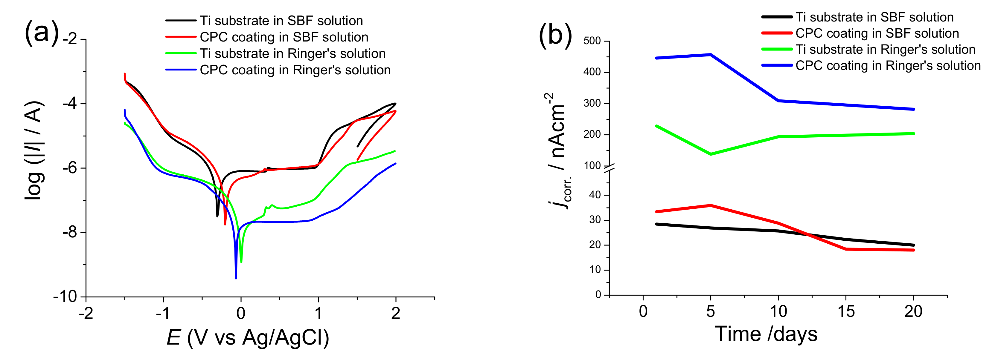
3.2.3. Electrochemical Evaluation of the Coatings
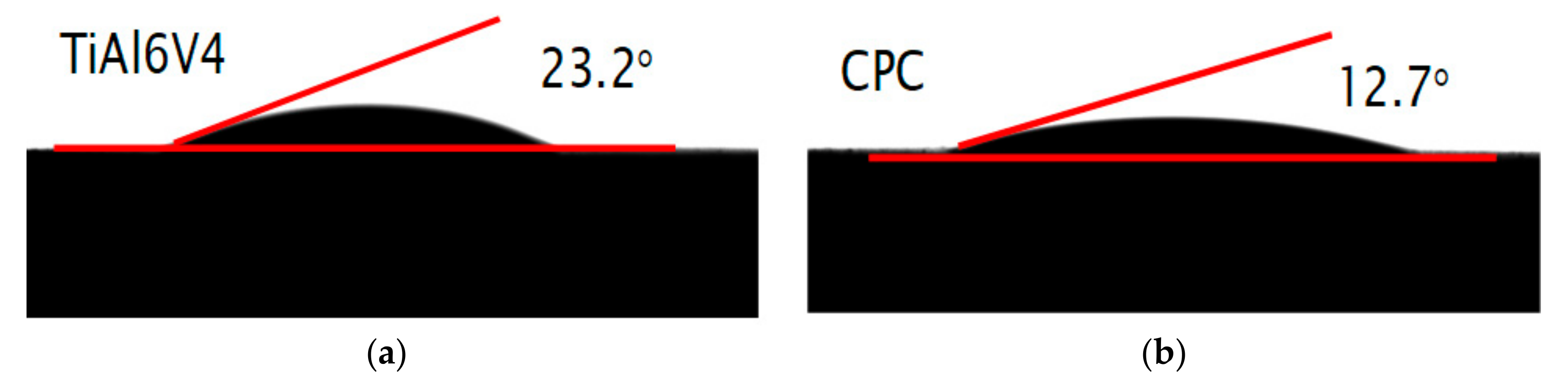
3.2.4. Contact Angle Measurements on CPC Coatings
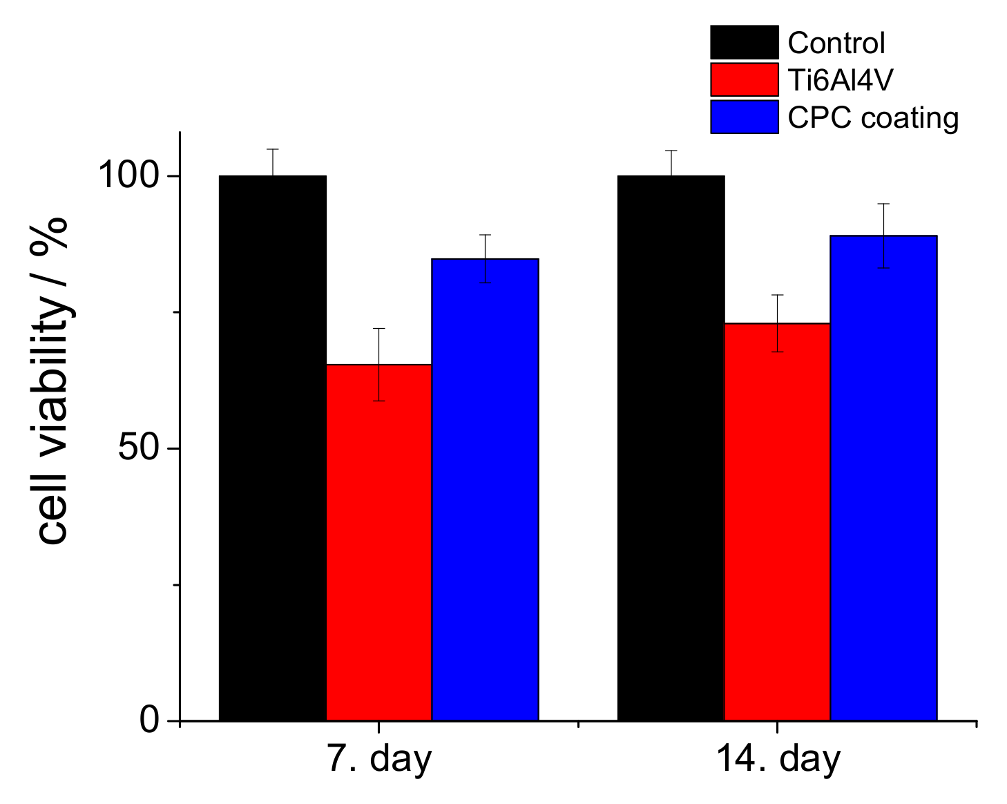
3.2.5. Cell Viability Measurements
4. Conclusions
Author Contributions
Funding
Acknowledgments
Conflicts of Interest
References
- Jacobs, J.J.; Hallab, N.J.; Urban, R.M.; Wimmer, M.A. Wear particles. J. Bone Jt. Surg. Am. 2006, 88 (Suppl. 2), S99–S102. [Google Scholar]
- Williams, D.F. On the mechanisms of biocompatibility. Biomaterials 2008, 29, 2941–2953. [Google Scholar] [CrossRef]
- Tengvall, P.; Lunstrom, I. Physico-chemical considerations of titanium as a biomaterial. Clin. Mater. 1992, 9, 115–134. [Google Scholar] [CrossRef]
- Ratner, B.D.; Bryant, S.J. Biomaterials: Where we have been and where we are going. Annu. Rev. Biomed. Eng. 2004, 6, 41–75. [Google Scholar] [CrossRef]
- Anderson, J.M. Biological responses to materials. Annu. Rev. Mater. Sci. 2001, 31, 81–110. [Google Scholar] [CrossRef]
- Goto, T.; Narushima, T.; Ueda, K. Bioceramic coating on titanium by physical and chemical vapor deposition. In Biological and Biomedical Coatings Handbook, 1st ed.; Zhang, S., Ed.; Taylor & Francis Group: Milton Park Abingdon, UK, 2011; Chapter 7; pp. 299–332. [Google Scholar]
- Espallargas, N.; Torres, C.; Muñoz, A.I. A metal ion release study of CoCrMo exposed to corrosion and tribocorrosion conditions in simulated body fluids. Wear 2015, 332–333, 669–678. [Google Scholar] [CrossRef]
- Atapour, M.; Wang, X.; Färnlund, K.; Wallinder, I.O.; Hedberg, Y. Corrosion and metal release investigations of selective laser melted 316L stainless steel in a synthetic physiological fluid containing proteins and in diluted hydrochloric acid. Electrochim. Acta 2020, 354, 136748. [Google Scholar] [CrossRef]
- Sansone, V.; Pagani, D.; Melato, M. The effects on bone cells of metal ions released from orthopaedic implants. A review. Clin. Cases Miner. Bone Metab. 2013, 10, 34–40. [Google Scholar] [CrossRef]
- Hallab, N.J.; Vermes, C.; Messina, C.; Roebuck, K.A.; Glant, T.T.; Jacobs, J.J. Concentration-and composition-dependent effects of metal ions on human MG-63 osteoblasts. J. Biomed. Mater. Res. 2002, 60, 420–433. [Google Scholar] [CrossRef]
- Nakonieczny, D.; Walke, W.; Majewska, J.; Paszenda, Z. Characterization of magnesia-doped yttria-stabilized zirconia powders for dental technology applications. Acta Bioeng. Biomech. 2014, 16, 99–106. [Google Scholar]
- Nakonieczny, D.; Paszenda, Z.K.; Basiaga, M.; Radko, T.; Drewniak, S.; Podwórny, J.; Bogacz, W. Phase composition and morphology characteristics of ceria-stabilized zirconia powders obtained via sol–gel method with various pH conditions. Acta Bioeng. Biomech. 2017, 19, 21–30. [Google Scholar]
- Salamanka, E.; Pan, Y.-H.; Tsai, A.I.; Lin, P.-Y.; Lin, C.-K.; Huang, H.-M.; Teng, N.-C.; Wang, P.D.; Chang, W.-J. Enhancement of osteoblastic-like cell activity by glow discharge plasma surface modified hydroxyapatite/β-tricalcium phosphate bone substitute. Materials (Basel) 2017, 10, 1347. [Google Scholar] [CrossRef]
- Takahashi, H.; Yashima, M.; Kakihana, M.; Yoshimura, M. Synthesis of stochiometric hydroxyapatite by a gel route from the aqueous solution of citric and phosphone acetic acids. Eur. J. Solid State Inorg. Chem. 1995, 32, 829–835. [Google Scholar]
- Gligorijevic, B.R.; Vilotijevic, M.; Scepanovic, M.; Vidovic, D.; Radovi, N.A. Surface structural heterogeneity of high power plasma-sprayed hydroxyapatite coatings. J. Alloy. Compd. 2016, 687, 421–430. [Google Scholar] [CrossRef]
- Tsui, Y.C.; Doyle, C.; Clyne, T.W. Plasma sprayed hydroxyapatite coatings on titanium substrates Part 1: Mechanical properties and residual stress levels. Biomaterials 1998, 19, 2015–2029. [Google Scholar] [CrossRef]
- Su, Y.; Li, K.; Tielens, F.; Wang, J. Effect of sprayed techniques on the surface microstructure and in vitro behavior of nano-HAp coatings. Mater. Sci. Eng. C 2020, 117, 111318. [Google Scholar] [CrossRef]
- Choy, K.L. Chemical vapour deposition of coatings. Prog. Mater. Sci. 2003, 48, 57–170. [Google Scholar] [CrossRef]
- Hontsu, S.; Hashimoto, Y.; Yoshikawa, Y.; Kusunoki, M.; Nishikawa, H.; Ametani, A. Fabrication of hydroxyl apatite coating titanium web scaffold using pulsed laser deposition method. J. Hard Tissue Biol. 2012, 21, 181–188. [Google Scholar] [CrossRef][Green Version]
- Eliaz, N.; Ritman-Hertz, O.; Aronov, D.; Weinberg, E.; Shenhar, Y.; Rosenman, G.; Weinreb, M.; Ron, E. The effect of surface treatments on the adhesion of electrochemically deposited hydroxyapatite coating to titanium and on its interaction with cells and bacteria. J. Mater. Sci. Mater. Med. 2011, 22, 1741–1752. [Google Scholar] [CrossRef]
- Thanh, D.T.; Nam, P.T.; Phuong, N.T.; Que, L.X.; Van Anh, N.; Hoang, T.; Lam, T.D. Controlling the electrodeposition, morphology and structure of hydroxyapatite coating on 316L stainless steel. Mater. Sci. Eng. C 2013, 33, 2037–2045. [Google Scholar] [CrossRef]
- Furko, M.; Balázsi, K.; Balázsi, C. Comparative study on preparation and characterization of bioactive coatings for biomedical applications—A review on recent patents and literature. Rev. Adv. Mater. Sci. 2017, 48, 25–51. [Google Scholar]
- Bosco, R.; Van Den Beucken, J.; Leeuwenburgh, S.; Jansen, J. Surface engineering for bone implants: A trend from passive to active surfaces. Coatings 2012, 2, 95–119. [Google Scholar] [CrossRef]
- Epinette, J.-A.; Manley, M.T. Fifteen Years of Clinical Experience with Hydroxyapatite Coatings in Joint Arthroplasty, 1st ed.; Geesink, R.G.T., Ed.; Springer: Paris, France, 2004; ISBN 978-2-287-00508-4. [Google Scholar] [CrossRef]
- Li, H. Thermal sprayed bioceramic coatings: nanostructured hydroxyapatite (HA) and HA-based composites. In Biological and Biomedical coatings Handbook, 1st ed.; Zhang, S., Ed.; Taylor & Francis Group: Milton Park Abingdon, UK, 2011; Chapter 4; pp. 137–202. [Google Scholar]
- Williams, D.F. Definitions in Biomaterials: Proceedings of a Consensus Conference of the European Society for Biomaterials. In Progress in Biomedical Engineering; Elsevier Science Ltd: New York, NY, USA, 1987. [Google Scholar]
- Orsini, G.; Piattelli, M.; Scarano, A.; Petrone, G.; Kenealy, J.; Piattelli, A.; Caputi, S. Randomized, controlled histologic and histomorphometric evaluation of implants with nanometer-scale calcium phosphate added to the dual acid-etched surface in the human posterior maxilla. J. Periodontol. 2007, 78, 209–218. [Google Scholar] [CrossRef] [PubMed]
- Paital, S.R.; Dahotre, N.B. Calcium phosphate coatings for bio-implant applications: Materials, performance factors, and methodologies. Mater. Sci. Eng. R 2009, 66, 1–70. [Google Scholar] [CrossRef]
- Bose, S.; Fielding, G.; Tarafder, S.; Bandyopadhyay, A. Trace element doping in calcium phosphate ceramics to understand osteogenesis and angiogenesis. Trends Biotechnol. 2013, 31, 594–605. [Google Scholar] [CrossRef]
- Gopi, D.; Karthika, A.; Nithiya, S.; Kavitha, L. In vitro biological performance of minerals substituted hydroxyapatite coating by pulsed electrodeposition method. Mater. Chem. Phys. 2014, 144, 75–85. [Google Scholar] [CrossRef]
- Kheradmandfard, M.; Fathi, M.H.; Ansari, F.; Ahmadi, T. Effect of Mg content on the bioactivity and biocompatibility of Mg-substituted fluorapatite nanopowders fabricated via mechanical activation. Mater. Sci. Eng. C 2016, 68, 136–142. [Google Scholar] [CrossRef]
- Uskokovic, V.; Uskokovic, D.P. Nanosized hydroxyapatite and other calcium phosphates: Chemistry of formation and application as drug and gene delivery agents. J. Biomed. Mater. Res. B Appl. Biomater. 2011, 96, 152–191. [Google Scholar] [CrossRef]
- Nerantzaki, M.; Filippousi, M.; Van Tendeloo, G.; Terzopoulou, Z.; Bikiaris, D.; Goudouri, O.M.; Detsch, R.; Grüenewald, A.; Boccaccini, A.R. Novel poly(butylene succinate) nanocomposites containing strontium hydroxyapatite nanorods with enhanced osteoconductivity for tissue engineering applications. Express Polym. Lett. 2015, 9, 773–789. [Google Scholar] [CrossRef]
- Seyedraoufi, Z.S.; Mirdamadi, S. Effects of pulse electrodeposition parameters and alkali treatment on the properties of nano hydroxyapatite coating on porous Mg–Zn scaffold for bone tissue engineering application. Mater. Chem. Phys. 2014, 148, 519–527. [Google Scholar] [CrossRef]
- Pana, J.; Prabakaranb, S.; Rajan, M. In-vivo assessment of minerals substituted hydroxyapatite/poly sorbitol sebacate glutamate (PSSG) composite coating on titanium metal implant for orthopedic implantation. Biomed. Pharmacother. 2019, 119, 109404. [Google Scholar] [CrossRef] [PubMed]
- Suchanek, K.; Bartkowiak, A.; Perzanowski, M.; Marszałek, M. From monetite plate to hydroxyapatite nanofibers by monoethanolamine assisted hydrothermal approach. Sci. Rep. 2018, 8, 15408. [Google Scholar] [CrossRef] [PubMed]
- Jokic, B.; Mitric, M.; Radmilovic, V.; Petrovic, S.D.R.; Janackovic, D. Synthesis and characterization of monetite and hydroxyapatite whiskers obtained by a hydrothermal method. Ceram. Int. 2011, 37, 167–173. [Google Scholar] [CrossRef]
- Duncan, J.; MacDonald, J.F.; Hanna, J.V.; Shirosaki, Y.; Hayakawa, S.; Osaka, A.; Skakle, J.M.S.; Gibson, I.R. The role of the chemical composition of monetite on the synthesis and properties of α-tricalcium phosphate. Mater. Sci. Eng. C 2014, 34, 123–129. [Google Scholar] [CrossRef]
- Cama, G.; Nkhwa, S.; Gharibi, B.; Lagazzo, A.; Cabella, R.; Carbone, C.; Dubruel, P.; Haugen, H.; Di Silvio, L.; Deb, S. The role of new zinc incorporated monetite cements on osteogenic differentiation of human mesenchymal stem cells. Mater. Sci. Eng. C 2017, 78, 485–494. [Google Scholar] [CrossRef]
- Macha, I.J.; Charvillat, C.; Cazalbou, S.; Grossin, D.; Boonyang, U.; Ben-Nissan, B. Comparative study of coral conversion, Part 3: Intermediate products in the first half an hour. J. Aust. Ceram. Soc. 2016, 52, 177–182. [Google Scholar]
- Ben-Nissan, B.C.; Charvillat, C.; Oktar, F.N.; Grossin, D. Comparative study of coral conversion, part 2: Microstructural evolution of calcium phosphate. J. Aust. Ceram. Soc. 2015, 51, 149–159. [Google Scholar]
- Cegla, R.-N.R.; Macha, I.J.; Ben-Nissan, B.; Grossin, D.; Heness, G.; Chung, R.-J. Comparative study of conversion of coral with ammonium dihydrogen phosphate and orthophosphoric acid to produce calcium phosphates. J. Aust. Ceram. Soc. 2014, 50, 154–161. [Google Scholar]
- Monasterio, N.; Ledesma, J.L.; Aranguiz, I.; Garcia-Romero, A.; Zuza, E. Analysis of electrodeposition processes to obtain calcium phosphate layer on AZ31 alloy. Surf. Coat. Technol. 2017, 319, 12–22. [Google Scholar] [CrossRef]
- Gopi, D.; Karthika, A.; Sekar, M.; Kavitha, L.; Pramod, R.; Dwivedi, J. Development of lotus-like hydroxyapatite coating on HELCDEB treated titanium by pulsed electrodeposition. Mater. Lett. 2013, 105, 216–219. [Google Scholar] [CrossRef]
- Chakraborty, R.; Sengupta, S.; Saha, P.; Das, K.; Das, S. Synthesis of calcium hydrogen phosphate and hydroxyapatite coating on SS316 substrate through pulsed electrodeposition. Mater. Sci. Eng. C 2016, 69, 875–883. [Google Scholar] [CrossRef] [PubMed]
- Gopi, D.; Indira, J.; Kavitha, L. A comparative study on the direct and pulsed current electrodeposition of hydroxyapatite coatings on surgical grade stainless steel. Surf. Coat. Techn. 2012, 206, 2859–2869. [Google Scholar] [CrossRef]
- Marashi-Najafi, F.; Khalil-Allafi, J.; Etminanfar, M.R. Biocompatibility of hydroxyapatite coatings deposited by pulse electrodeposition technique on the Nitinol superelastic alloy. Mater. Sci. Eng. C 2017, 76, 278–286. [Google Scholar] [CrossRef] [PubMed]
- Zou, Z.; Liu, X.; Chen, L.; Lin, K.; Chang, J. Dental enamel-like hydroxyapatite transformed directly from monetite. J. Mater. Chem. 2012, 22, 22637–22641. [Google Scholar] [CrossRef]
- Shih, W.J.; Chen, Y.H.; Wang, S.H.; Li, W.L.; Hon, M.-H.; Wang, M.-C. Effect of NaOH(aq) treatment on the phase transformation and morphology of calcium phosphate deposited by an electrolytic method. Cryst. Growth 2005, 285, 633–641. [Google Scholar] [CrossRef]
- Chen, H.-T.; Wang, M.-C.; Chang, K.-M.; Wang, S.-H.; Shih, W.J.; Li, W.-L. Phase transformation and morphology of calcium phosphate prepared by electrochemical deposition process through alkali treatment and calcination. Metall. Mater. Trans A 2014, 45, 2260–2269. [Google Scholar] [CrossRef]
- Shih, W.J.; Wang, M.C.; Chang, K.M.; Wang, C.L.; Wang, S.H.; Li, W.L.; Huang, H.H. Phase transformation of calcium phosphates by electrodeposition and heat treatment. Metall. Mater. Trans. A 2010, 41, 3509–3516. [Google Scholar] [CrossRef]
- Huang, C.; Cao, P. Tuning Ca:P ratio by NaOH from monocalcium phosphate monohydrate (MCPM). Mater. Chem. Phys 2016, 181, 159–166. [Google Scholar] [CrossRef]
- Prado Da Silva, M.H.; Lima, J.C.H.; Soares, G.A.; Elias, C.N.; de Andrade, M.C.; Best, S.M.; Gibson, I.R. Transformation of monetite to hydroxyapatite in bioactive coatings on titanium. Surf. Coat. Technol. 2001, 137, 270–276. [Google Scholar] [CrossRef]
- Koutsopoulos, S. Synthesis and characterization of hydroxyapatite crystals: A review study on the analytical methods. J. Biomed. Mater. Res. 2002, 62, 600–612. [Google Scholar] [CrossRef]
- Berzina-Cimdina, L.; Borodajenco, N. Research of calciumphosphates using Fourier transform infrared spectroscopy. In Infrared Spectroscopy—Materials Science Engineering and Technology; Theophile, T., Ed.; IntechOpen Ltd: London, UK, 2012; pp. 123–148. ISBN 978-953-51-0537-4. [Google Scholar]
- Roveri, N.; Falini, G.; Sidoti, M.C.; Tampieri, A.; Landi, E.; Sandri, M.; Parma, B. biologically inspired growth of hydroxyapatite nanocrystals inside self-assembled collagen fibers. Mater. Sci. Eng. C 2003, 23, 441–446. [Google Scholar] [CrossRef]
- Singh, A. Hydroxyapatite, a biomaterial: Its chemical synthesis, characterization and study of biocompatibility prepared from shell of garden snail, Helix aspersa. Bull. Mater. Sci. 2012, 35, 1031–1038. [Google Scholar] [CrossRef]
- Jimbo, R.; Ivarsson, M.; Koskela, A.; Sul, Y.T.; Johansson, C.B. Protein adsorption to surface chemistry and crystal structure modification of titanium surfaces. J. Oral Maxillofac. Res. 2010, 1, e3. [Google Scholar] [CrossRef] [PubMed]
- Aronov, D.; Rosen, R.; Ron, E.Z.; Rosenman, G. Tunable hydroxyapatite wettability: Effect on adhesion of biological molecules. Proc. Biochem. 2006, 41, 2367–2372. [Google Scholar] [CrossRef]
- Zhao, G.; Schwartz, Z.; Wieland, M.; Rupp, F.; Geis-Gerstorfer, J.; Cochran, D.L.; Boyan, B.D. High surface energy enhances cell response to titanium substrate microstructure. J. Biomed. Mater. Res. A 2005, 74, 49–58. [Google Scholar] [CrossRef]
- Kilpadi, D.V.; Lemons, L.E. Surface energy characterization of unalloyed titanium implants. J. Biomed. Mater. Res. 1994, 28, 1419–1425. [Google Scholar] [CrossRef]
- Eriksson, C.; Nygren, H.; Ohlson, K. Implantation of hydrophilic and hydrophobic titanium discs in rat tibia: Cellular reactions on the surfaces during the first 3 weeks in bone. Biomaterials 2004, 25, 4759–4766. [Google Scholar] [CrossRef]
- Anselme, K. Osteoblast adhesion on biomaterials. Biomaterials 2000, 21, 667–681. [Google Scholar] [CrossRef]
- Fan, R.R.; Zhou, L.X.; Song, W.; Li, D.X.; Zhang, D.M.; Ye, R.; Zheng, Y.; Guo, G. Preparation and properties of g-TTCP/PBS nanocomposites and its in vitro bio-compatibility assay. Int. J. Biol. Macromol. 2013, 59, 227–234. [Google Scholar] [CrossRef]
- Kilpadi, K.L.; Chang, P.L.; Bellis, S.L. Hydroxylapatite binds more serum proteins, purified integrins, and osteoblast precursor cells than titanium or steel. J. Biomed. Mater. Res. 2001, 57, 258–267. [Google Scholar] [CrossRef]
- Thian, E.S.; Ahmad, Z.; Huang, J.; Edirisinghe, M.J.; Jayasinghe, S.N.; Ireland, D.C.; Brooks, R.A.; Rushton, N.; Bonfield, W.; Best, S.M. The role of surface wettability and surface charge of electrosprayed nanoapatites on the behaviour of osteoblasts. Acta Biomater. 2010, 6, 750–755. [Google Scholar] [CrossRef] [PubMed]


| Deposition Parameters | Samples | ||||
|---|---|---|---|---|---|
| S1 | S2 | S3 | S4 | S5 | |
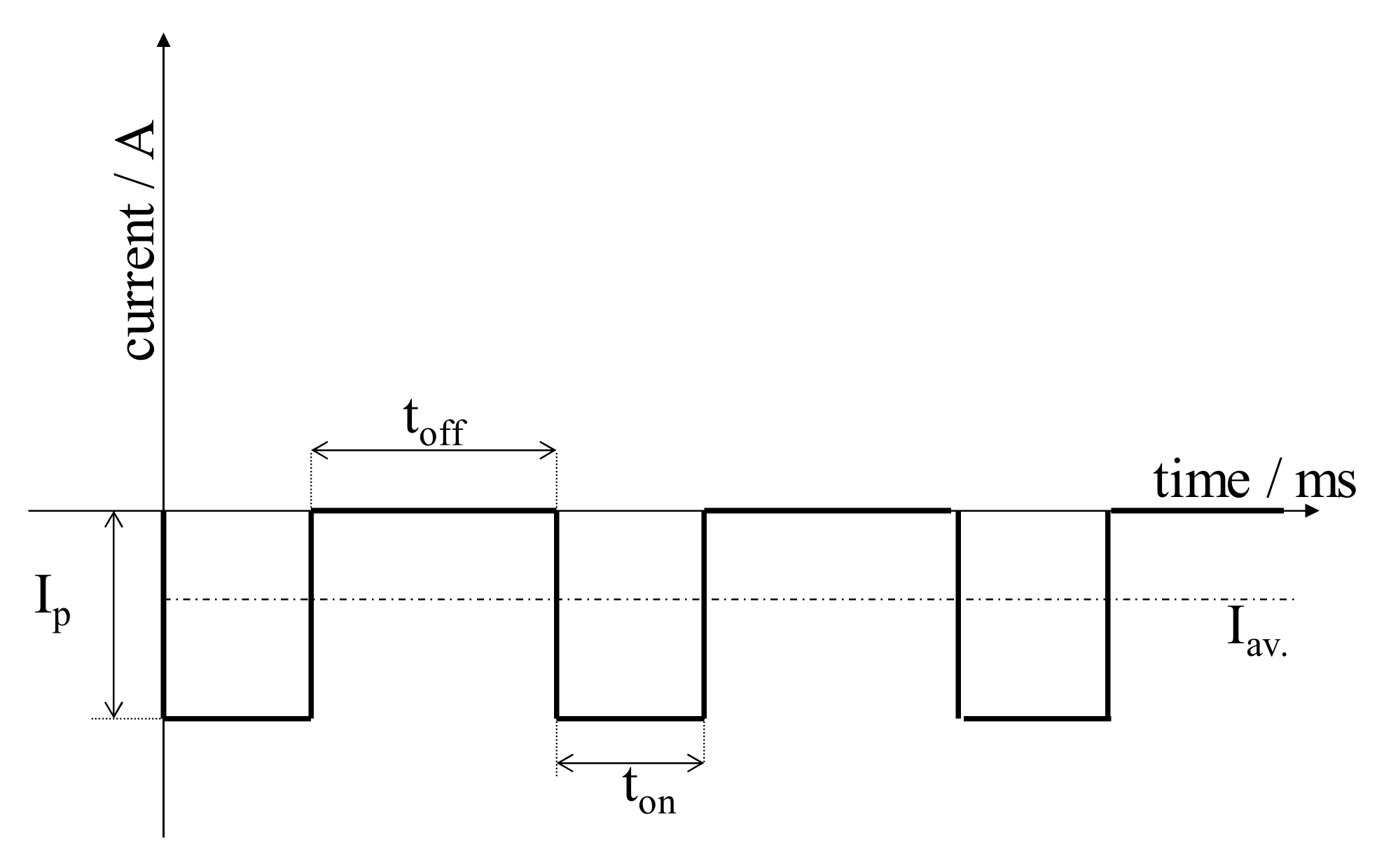
| ton/ms | 5 | 5 | 1 | 1 | 1 |
| toff/ms | 5 | 5 | 10 | 10 | 10 |
| ip/A·cm−2 | 0.4 | 1 | 5 | 5 | 5 |
| Surface treatment after deposition | - | - | - | 1 M NaOH solution, 70 °C for 2 h | Heat treatment at 900 °C for 30 min |
| Reagent | Concentration/gL | |
|---|---|---|
| SBF | Ringer’s | |
| NaCl | 7.996 | 9.00 |
| NaHCO3 | 0.350 | 0.20 |
| KCl | 0.224 | 0.43 |
| CaCl2 | 0.278 | 0.24 |
| K2HPO4·3H2O | 0.228 | - |
| MgCl2·6H2O | 0.305 | - |
| Na2SO4 | 0.071 | - |
| (CH2OH)3CNH2 (TRIS) | 6.057 | - |
| 1M-HCl | 40.80 | - |
© 2020 by the authors. Licensee MDPI, Basel, Switzerland. This article is an open access article distributed under the terms and conditions of the Creative Commons Attribution (CC BY) license (http://creativecommons.org/licenses/by/4.0/).
Share and Cite
Furko, M.; Balázsi, C. Calcium Phosphate Based Bioactive Ceramic Layers on Implant Materials Preparation, Properties, and Biological Performance. Coatings 2020, 10, 823. https://doi.org/10.3390/coatings10090823
Furko M, Balázsi C. Calcium Phosphate Based Bioactive Ceramic Layers on Implant Materials Preparation, Properties, and Biological Performance. Coatings. 2020; 10(9):823. https://doi.org/10.3390/coatings10090823
Chicago/Turabian StyleFurko, Monika, and Csaba Balázsi. 2020. "Calcium Phosphate Based Bioactive Ceramic Layers on Implant Materials Preparation, Properties, and Biological Performance" Coatings 10, no. 9: 823. https://doi.org/10.3390/coatings10090823
APA StyleFurko, M., & Balázsi, C. (2020). Calcium Phosphate Based Bioactive Ceramic Layers on Implant Materials Preparation, Properties, and Biological Performance. Coatings, 10(9), 823. https://doi.org/10.3390/coatings10090823