Article

Femtosecond Laser-Induced Damage Characterization of Multilayer Dielectric Coatings

ELI Beamlines, Institute of Physics of The Czech Academy of Sciences, Za Radnicí 835, 252 41 Dolní Břežany, Czech Republic
*
Author to whom correspondence should be addressed.
Coatings 2020, 10(6), 603; https://doi.org/10.3390/coatings10060603
Submission received: 18 May 2020 / Revised: 12 June 2020 / Accepted: 22 June 2020 / Published: 26 June 2020
(This article belongs to the Special Issue Visual Effects Coatings and Surfaces)

Abstract

:
The laser-induced damage threshold (LIDT) of optical components is one of the major constraints in developing high-power ultrafast laser systems. Multi-layer dielectric (MLD) coatings-based optical components are key parts of high-power laser systems because of their high damage resistance. Therefore, understanding and characterizing the laser-induced damage of MLD coatings are of paramount importance for developing ultrahigh-intensity laser systems. In this article, we overview the possible femtosecond laser damage mechanisms through damage morphologies in various MLD optical coatings tested in our facility. To evaluate the major contributions to the coating failure, different LIDT test methods (R-on-1, ISO S-on-1 and Raster Scan) were carried out for a high reflective hybrid Ta2O5/HfO2/SiO2 MLD mirror coating at a pulse duration of 37 fs. Different LIDT test methods were compared due to the fact that each test method exposes the different underlying damage mechanisms. For instance, the ISO S-on-1 test at a higher number of laser pulses can bring out the fatigue effects, whereas the Raster Scan method can reveal the non-uniform defect clusters in the optical coating. The measured LIDT values on the sample surface for the tested coating in three test methods are 1.1 J/cm2 (R-on-1), 0.9 J/cm2 (100k-on-1) and 0.6 J/cm2 (Raster Scan) at an angle of incidence of 45 deg. The presented results reveal that the performance of the tested sample is limited by coating defects rather than fatigue effects. Hence, the Raster Scan method is found to be most accurate for the tested coating in evaluating the damage threshold for practical applications. Importantly, this study demonstrates that the testing of different LIDT test protocols is necessary in femtosecond regime to assess the key mechanisms to the coating failure.

1. Introduction

The laser-induced damage of optical components has become an ineluctable issue since the invention of lasers. Along with the developments in high-damage resistance optical coating technologies, the evolution of the development of laser technologies such as mode locking, chirped pulse amplification and optical parametric amplification led to the current state-of-the-art high-power laser systems [1,2,3,4,5,6]. The development of high energy ultrashort lasers has attracted many research domains because of their high peak powers (greater than 1 PW) and high intensities (greater than 1022 W/cm2) at focal volume. These features of high-power lasers enable access to new material states in laboratory conditions [7]. Therefore, high-power ultrafast lasers render the wide spectrum of applications in science, including relativistic laser–matter interactions and compact laser accelerators [8,9,10], laboratory astrophysics [11], proton therapy [12] and soft and hard x-rays generation [13,14].
The maximum operational fluence of high-power lasers is majorly limited by the laser-induced damage threshold (LIDT) fluence of the optical components. For an optimal performance of the optical system, the lasers need to use high-threshold optical coatings that meet the operational laser fluence level requirements. Expanding the beam size can be one alternative solution to lower the peak fluence, but this has its own limitations because of the size and cost. Multilayer dielectric (MLD) coatings are of interest for high-power laser systems because of their low absorption. Because of the high reflectivity and controlled group delay dispersion, MLD mirrors are an ideal choice for femtosecond (fs) lasers. Therefore, the development of high-threshold dielectric coatings has ever increasing demand. Hence, high-resistance optical coatings, various optical coating technologies and large area coating infrastructures have received great attention in recent years. To reach out to the demand for high threshold coatings, a lot of effort has been made to increase the threshold of MLD coatings by specific optical designs, coating methods and optimizing the electric field distribution on the coating surface [15,16,17,18].
It is well known that the damage threshold of MLD optical coatings is strongly dependent on the duration of laser pulses by involving different type of laser-induced mechanisms. For instance, the laser-induced damage for nanosecond laser pulses is majorly linked to thermal properties of the optical coating material. In long pulse regimes, the defect centers on the coating play a major role. The defects act as absorbers that can induce thermo-mechanical phenomena like melting, evaporation and cracking [19]. In the case of ultrafast regimes, because of the ultrahigh intensities and wide bandgap of the dielectric materials, the laser damage is linked to nonlinear excitation of free carriers and consequent relaxation mechanisms. Hence, the laser-induced damage in the fs regime is majorly governed by electronic excitation and electric field intensity in coatings. In this regime, defects and impurities play a negligible role [20].
Apart from the pulse duration, it has been found that the coating deposition method also plays a key role in the optical performance of the coatings. For instance, the coatings deposited by electron beam evaporation produce relatively porous films and contain low internal stress [21]. Therefore, these coatings were found to be highly resistant for high-energy nanosecond laser applications. In contrast, dense coatings produced by ion beam sputtering (IBS) have high damage resistance in the fs regime [22]. Besides the type of coating technology, the laser damage resistance of the optical coatings is also dependent on intrinsic properties of coating materials, used laser parameters: wavelength, pulse duration and repetition rate, and coating designs. Therefore, a lot of research has been put forward in order to understand the formation and growth of the laser-induced damage depending on laser parameters, material properties of the coating and environmental conditions of the optics usage [23].
As the laser-induced damage depends on many parameters, understanding the laser-induced damage mechanisms and high-resistance optical components are still major limitations for high-power lasers development. Hence, in this article, we give an overview of fs laser-induced damage, types of damage in MLD coatings and different test methods to characterize the damage resistance and damage threshold of the coatings. Additionally, the critical mechanisms for the coating failure in practical applications is not clear in literature. By combining the different test method results, we reveal the critical mechanisms that dominantly lead to the failure of tested optical coating.

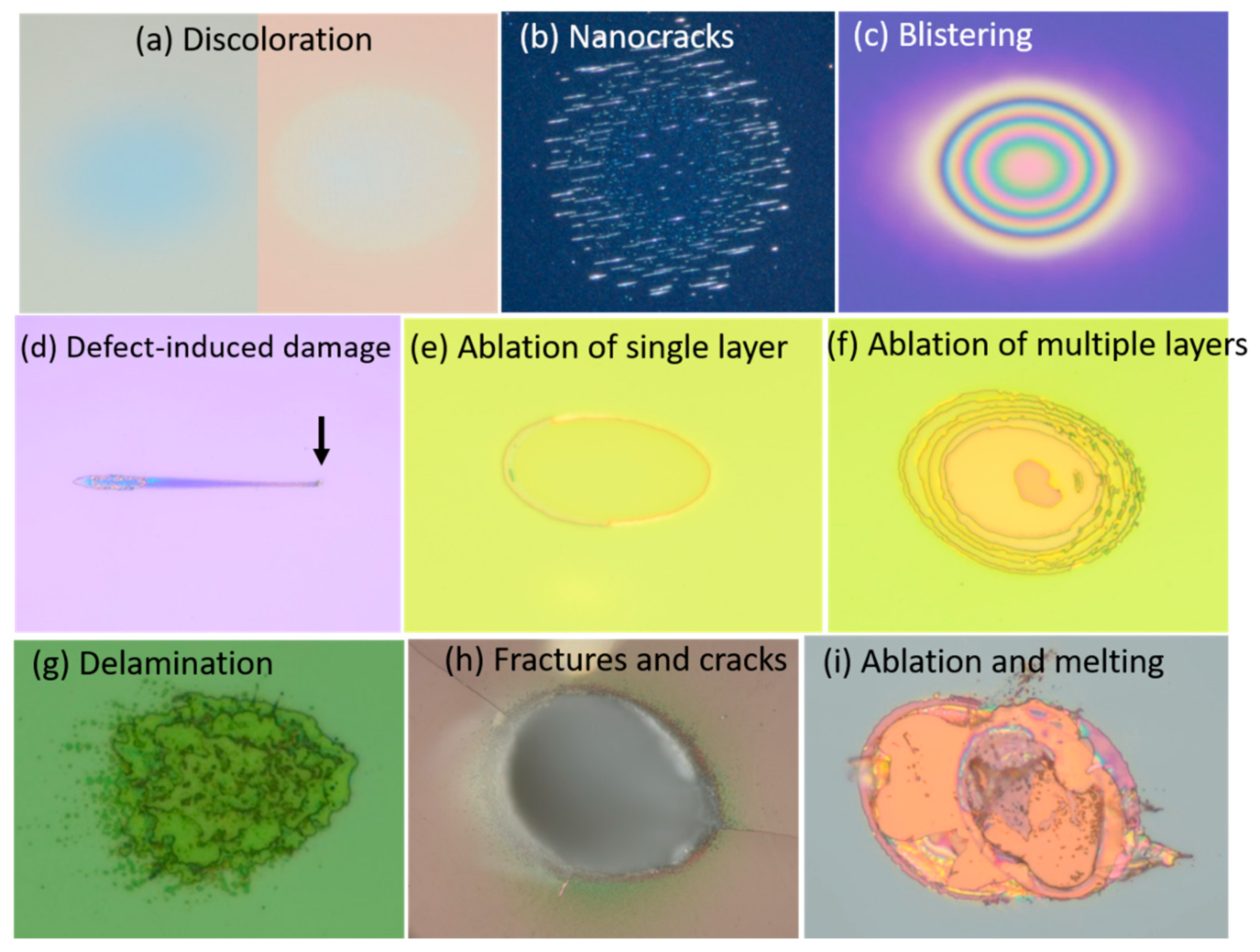
2. Fs Laser-Induced Damage of Multilayer Dielectric Coatings

In this section, we overview the fs laser damage, experimental determination of the damage threshold and various types of laser-induced damage in MLD optical thin films. The static damage morphologies can help us to understand the underlying physical mechanisms involved in the damage. The possible fs damage mechanisms of MLD optical coatings are revealed by analyzing damage morphologies of various tested optical coatings in our facility.
Above a certain power/energy density, the laser irradiation on the optical coating induces permanent changes. Any permanent change by the laser irradiation that is visible under the Nomarski or Dark-filed microscopy at 100–150× magnification can be considered as laser-induced damage. These permanent changes on the coating cause losses in reflectivity or transmission depending on its optical function. Apart from the energy loss, if the optics are further exposed in the optical setup, the damage on the optics can also induce the laser beam profile by generating the hotspots from the damaged pits. These hot spots in the beam profile could damage other optics. Therefore, the damaged optical component has to be identified in early stages of the damage in optical setups to stop the damage propagation to other optics mostly in high repetition rate lasers. The highest fluence that an optical coating can withstand is called the damage threshold. Hence, choosing the appropriate optics with the required damage threshold is of upmost importance for working with high-power lasers. As per the ISO 21254 standard [24], LIDT is defined as the maximum amount of energy density for which the extrapolated damage probability is zero.
In the fs regime, nonlinear photoionization mechanisms in dielectrics create the excitation of free carriers because of the wide bandgap of dielectrics. The consequent relaxation of free carriers in later time scales of the excitation lead to the permanent damage. The damage mechanisms in the fs regime were studied in bulk and on the surface of dielectrics and dielectric coatings. It was found that damage mechanisms in the fs regime are dominated by electron dynamics. The dielectric breakdown in the fs regime was found to be deterministic and can be explained by nonlinear photoionization mechanisms [20,25]. Therefore, the damage behavior in the fs regime is deterministic and the LIDT probability curve is sharp in most cases. Hence, the coating is damaged with high probability above the damage threshold. There was a big debate in the community on the fs laser damage criteria (dielectric breakdown) about whether it can be attributed to critical free carrier density or critical energy deposition per unit volume to induce the permanent laser damage [25,26]. It was justified in bulk dielectrics that free carrier density may not necessarily reach to critical density and one and two orders of lower critical electron densities can induce the permanent damage [27]. For the multi-pulse irradiation, a decrease in breakdown threshold was observed compared to a single pulse intrinsic threshold. These phenomena are often referred as incubation effects [28] or fatigue effects [29]. These effects have been observed in various kinds of materials such as glasses [30,31,32], crystals [31,33] and polymers [34].
The properties of coating materials and their response to the ultrafast excitation can define the type of laser damage occurring during the free carrier relaxation. Therefore, spatial features of the damage morphologies can infer the physical mechanisms associated with the laser damage. In the following section, we give an overview of different types of fs laser-induced damage in our tested various MLD optical coatings. Figure 1 shows various types of laser damage in the fs regime. The typical observed damage-types are described below:
Discoloration: In some of the optical coatings, around the damage threshold, we observed the discoloration till the threshold for ablation of material as in Figure 1a. This soft-nature of the damage could not affect the reflectivity significantly but can expand this discoloration with the accumulation of pulses. This may act as a precursor for catastrophic damage at higher fluences and or longer exposure.
Nanostructures: The laser-induced nanostructures (nanocracks type structures) were found on the surface of coatings after a threshold number of pulses. It was found that the laser-induced nano bumps and inhomogeneities in the surface roughness for an early number of pulses trigger nanocrack formation [35]. The typical formation of nanostructures on the coating surface is shown in Figure 1b.
Blistering: The fs laser irradiation of optical coatings could lead to dense electron plasma close to the temperatures sufficient for softening of the coating. The combination of compressive stress relaxation and the forced expansion of the softened film could lead to the formation of the blister [36]. The types of damage morphologies due to laser-induced blistering on MLD coatings are shown in Figure 1c. The interference rings present in the images are due to the constructive interference in optical microscopy as height of the blister changes radially.
Defect-induced damage: We found that defects on the surface of the coatings can significantly reduce the LIDT [37]. Typical defect-induced damage morphology is shown in Figure 1d. These types of damage were mostly observed in coatings deposited by evaporation techniques like the e-beam coating method, as a higher density of coating defects can be expected. The particulate contamination on the coating may also cause these type of damage.
Laser ablation: There can be several types of laser ablation depending on the irradiated fluence levels above the damage threshold, number of pulses of irradiation, pulse repetition rates and thermomechanical properties of the coating materials. At a lower number of pulses, the irradiation of one or two pulses, it can be possible to ablate the single/top layer of the coating. When increasing the number of pulses, multiple coating layers can be removed. These two comparisons can be shown in Figure 1e,f. At much higher fluences above the damage threshold, other different types of ablation are shown in Figure 1g–i, like the delamination-type of optical damage, ablation with cracks and fractures and melting of the coating.

3. Experimental Details

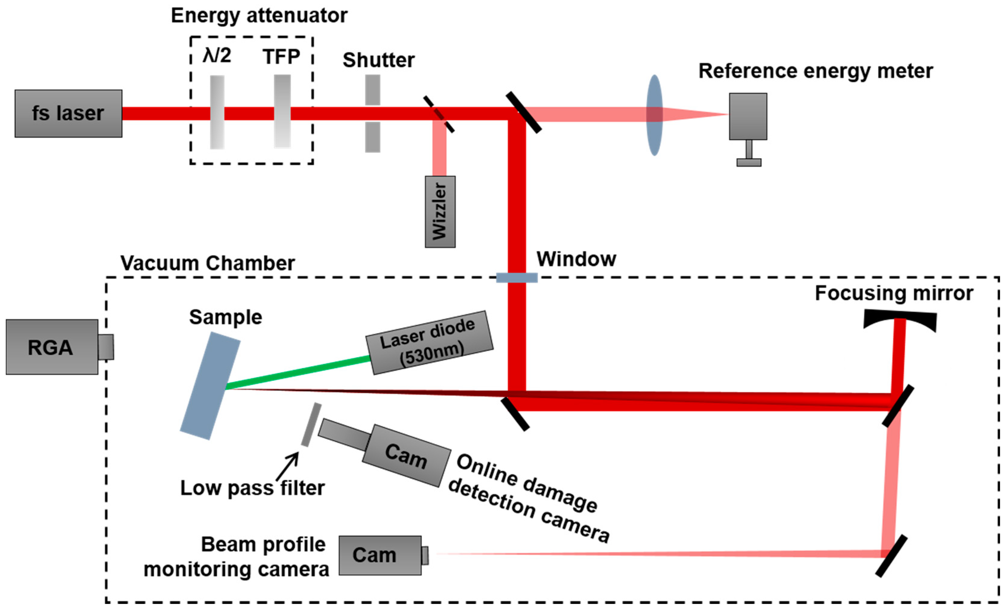
3.1. Experimental Setup

The schematic experimental setup of LIDT test station is shown in Figure 2. An ultrashort laser (Astrella Ti:Sapphire system, Coherent Inc., Santa Clara, CA, USA) with a center wavelength at 800 nm, pulse duration of 37 fs and pulse repetition rate of 1 kHz is used. The laser beam is focused onto a sample surface using spherical focusing mirror with a focal length of 80 cm. The beam size (effective beam diameter) on the sample surface is ~130 µm. The fluence in the focal plane of the sample is varied with the combination of wave-plate and thin-film polarizer. The pulse duration is measured using Wizzler from Fastlite, France. The beam size is monitored in online by taking a leak from dielectric mirror at an equivalent distance to the sample’s focal plane. The in-situ damage formation is observed using a damage detection camera with the scattering light from the 532 nm continuous wave diode laser. The parasitic light from the 800 nm fs laser was blocked using a low pass filter placing in front of the damage detection camera. The sample is mounted on a rotational stage for varying the desired angle of incidence (AOI) and two translation stages provide the sample movement in horizontal and vertical directions. Apart from the online diagnostics for the damage detection, the final evaluation of the damage sites was completed in ex-situ using an optical microscope (BX-51M, Olympus, Shinjuku-ku, Tokyo, Japan) in differential interference contrast, dark or bright field modes.
During the experiments, the laser energy is monitored in the sample focal plane using a reference photodiode energy meter (PD 10-PJ-C, Ophir Optronics Solutions Ltd., Har Hotzvim, Jerusalem, Israel). The reference energy meter is calibrated with an energy meter (PE 25-C, Ophir Optronics Solutions Ltd., Har Hotzvim, Jerusalem, Israel) in the beam path of final optics to the sample before and after the measurements. As shown in Figure 2, the LIDT setup is enclosed in a vacuum chamber. The Residual Gas Analyzer (RGA) is mounted to the vacuum chamber to monitor the residual components. All the LIDT measurements were carried out in high vacuum ~10−6 mbar, at similar atmospheric conditions as the components that are used or going to be used in the facility.

3.2. Test Methods

The damage threshold of the optics can be determined by several methods depending on the user’s interest. The single pulse test (ISO 21254-2, 1-on-1) method [38] is used to find the intrinsic damage threshold of the optics. The multi-pulse test (ISO 21254-2, S-on-1) method [38] is used to evaluate the damage threshold by considering fatigue/accumulation effects. The S-on-1 test method at high number of pulses accounting the accumulation effects may offer the threshold that is close to real operating conditions of the optics. Therefore, S-on-1 threshold at high number of laser pulses can provide the rough life-time of the optics when there is no other significant effects like coating defects and non-uniformities in the coating. The coating quality of the optics and accountability of coating defect clusters over the larger surface areas of the optics can be assessed by Raster Scan test method. When there is a limitation of the usable sample area, a fast and easy method to know the damage threshold of the optics is the Ramp test (R-on-1). The detailed procedures of these test methods are discussed below.
The ISO standard, ISO 21254-2 multi-pulse test is also called as S-on-1 where ‘S’ refers to the number of pulses exposed at each site to estimate the LIDT at a given ‘S’ number of pulses. If we irradiate the single pulse, i.e., S -> 1 called 1-on-1. The 1-on-1 test method used to estimate the intrinsic damage threshold of the optical materials. This test method is useful to study and compare the intrinsic material properties of the coating materials. However, in real practical applications to estimate the durability of the optics, it is important to consider the multi-pulse exposure effects such as fatigue/accumulation effects [39]. These accumulation effects may be related to discoloration on the coating surface or nanostructures formation which grow with the number of laser pulses [35]. In order to account the substantial accumulation effects, we expose the possible maximum number of pulses (100 k at 1 kHz) to estimate the damage threshold. As per the ISO standard procedure, we irradiated a constant number of pristine/fresh sites and each site was exposed to a constant number (100,000) of pulses for different fluences. For each fluence level, total five number of sites were exposed. The damage probability is estimated from these tested sites at various fluences. In this method, LIDT is defined as the maximum fluence for which extrapolated damage probability is zero. The laser exposure was stopped before reaching 100,000 pulses if the damage was detected by the damage indicator for early number of pulses. This is performed to prevent the debris contamination on the sample.
In order to validate the coating quality in larger areas and account the significant number of defects or impurities in the coating, Raster Scan method is used. In general, this method is employed for the larger size optical coatings. In the Raster Scan method, the sample was scanned over different areas (3 mm × 1.5 mm) of the optics for a stationary laser beam at a constant laser fluence. By tuning the scanning speed, the horizontal beam overlap was set to 90% and the vertical beam overlap was set to 40%. One hundred pulses were exposed per overlap. The damage threshold was considered as the lowest fluence with no visible changes on the sample due to laser scan by ex-situ microscopic examination. Multiple scan areas with different fluences above and below the damage threshold were carried out. In order to have consistent results, we repeated at least three scans for each fluence. To avoid the debris on fresh areas of the sample by previous exposures or scans, we used the bottom to top exposure approach. This method found to be effective to avoid the debris distribution on the fresh areas of the sample.
R-on-1 test method is used when there is a limited optical space/size available for tests. In this test method, the laser fluence was increased step by step starting from the lower to higher fluences until the damage was observed. In each step, a constant number of pulses (1400–1500 pulses per fluence) was exposed for each fluence level. The exposure of the laser was stopped immediately after the in-situ damage detection. To see the relative changes in the scattering signal due to fs laser irradiation, background scattering signal due to the sample surface was normalized to zero before starting the measurement for each site, i.e., without fs laser exposure. During the laser exposure, if the fluence level is above the damage threshold, there is a sudden increase in the scattering signal from the normalized value. In this method, the damage threshold fluence is determined as the lowest fluence for which there is a change in the scattering signal in in-situ damage detection camera generally above the set value of the damage threshold indicator. The damaged sites were also confirmed by ex-situ microscope examination.

3.3. Materials

The measurements were performed on a Ta2O5/HfO2/SiO2 quarter wave stack MLD mirror which is optimized for fs-applications and has a Group Delay Dispersion (GDD) of 0 fs2. This sample was provided by a kind cooperation of Laseroptik GmbH. The coating was deposited using IBS technique on a fused silica substrate with diameter of 25 mm and thickness of 6.35 mm. The coating is designed for a high reflectivity (Rs > 99.9%) over the band width of 180 nm at an AOI 45 deg with a central wavelength of 800 nm. The specifications of the sample are highlighted in Table 1.

4. LIDT Results

In this section, we present the LIDT results obtained from different test methods: ISO standard S-on-1, Raster Scan and R-on-1 for a Ta2O5/HfO2/SiO2 multilayer stack coating. The tested MLD coating is optimized for a high reflectivity and low GDD for a central wavelength of 800 nm at AOI 45 deg. Therefore, LIDT tests were carried out at an AOI of 45 deg and S-polarization.

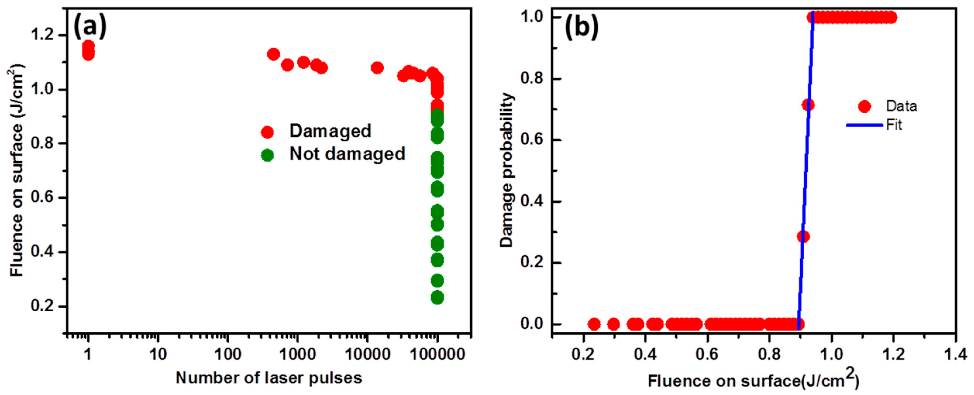
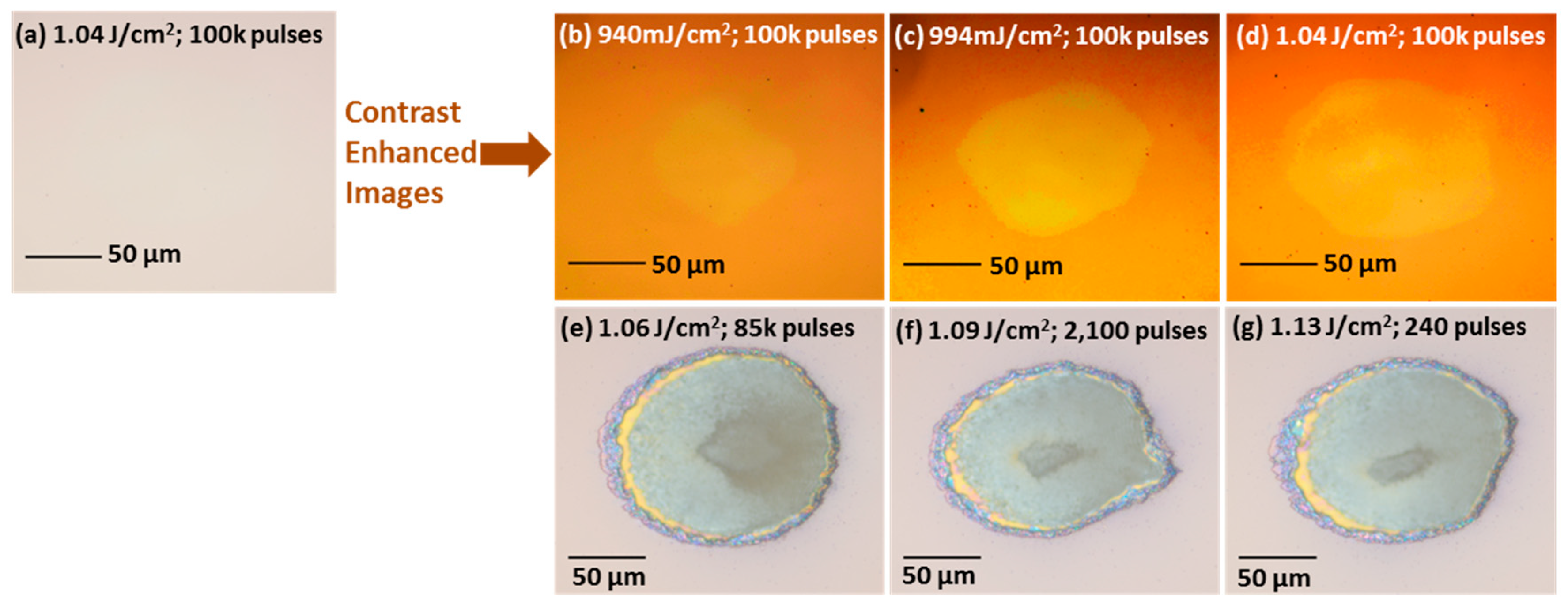
4.1. ISO S-on-1 Method

The S-on-1 data are shown in Figure 3. The plot of laser fluence vs. number of laser pulses is shown in Figure 3a indicating damaged sites and un-damaged sites. The damage probability for a given fluence and number of pulses was calculated using the binning procedure described in ISO 21254-2. The plot of damage probability vs. laser fluence with the linear fit is shown in Figure 3b. The laser fluence range was chosen above and below the 100% damage probability. In this procedure, the damage probability vs. laser fluence plot was fitted with a line. The extrapolation to highest fluence of the zero damage probability represents the damage threshold value. The damage threshold for 100k-on-1 resulting from the fit is ~0.9 ± 0.09 J/cm2.
Figure 4 elucidates the evolution of the damage formation with increasing laser fluence. Figure 4a is a Nomarski microscopy image around the damage threshold at 1.04 J/cm2. We observed faint changes on the coating after the laser exposure close to the damage threshold. To see these hardly-visible features, we enhanced the contrast of the images as shown in Figure 4b–d. The faintly visible changes on the coating and their growth with increasing laser fluence may refer to the laser-induced stress. Around the threshold, the laser-induced stress type modifications were considered as damaged sites in Figure 3a. The further increase in laser fluence led to catastrophic damage as seen in Figure 4e–g. From Figure 3 and Figure 4, it can be seen that there is a sharp transition from undamaged spots to catastrophic damage apart from the very narrow laser-induced stress region.

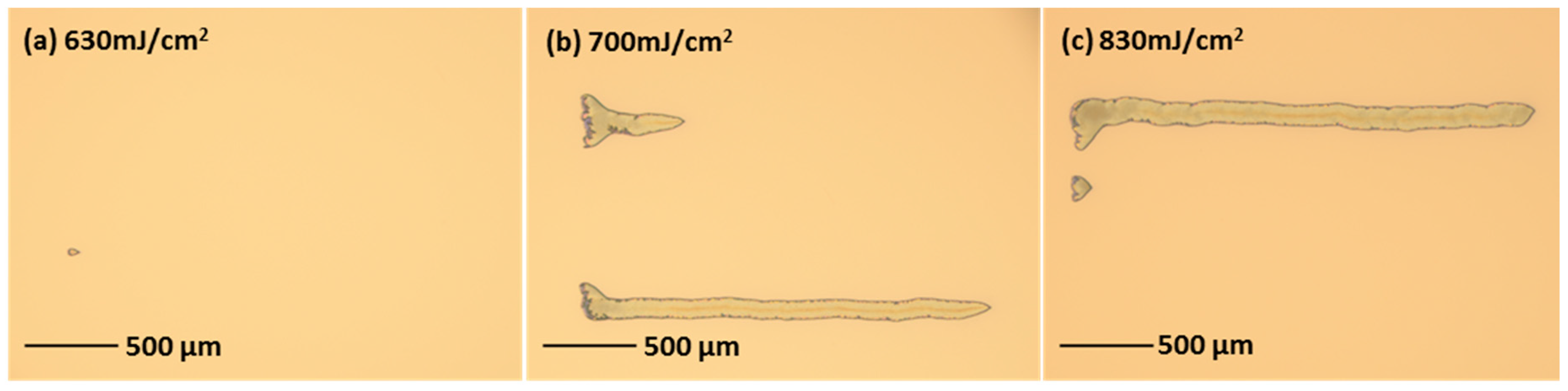
4.2. Raster Scan Method
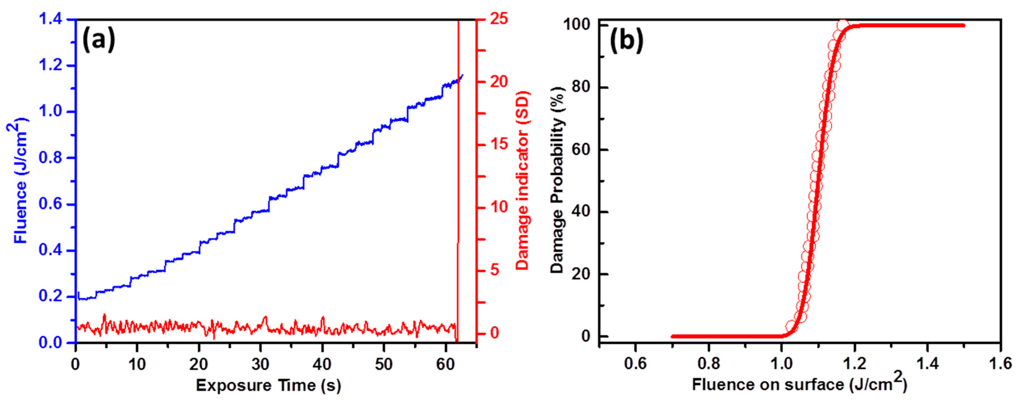
The typical surface damage morphologies from the Raster Scan method are shown in Figure 5 at various laser fluences. The full area of the scan is shown. As seen from the figure, we observed only the catastrophic-type damage. From Figure 5a–c, it is evident that the confinement of the damage is to the specific locations on the coating over large scanning areas represent the presence of coating defects in the sample. As the horizontal beam overlap is larger, the damage propagation can be seen in that direction. It is important to note that no visible defects/particles were observed on the sample surface before the measurements in the damage detection camera at a resolution of ~2.5 µm/pixel. The damage threshold found by this method is 0.6 J/cm2. This means no visible damage is observable under the Nomarski microscope.

4.3. R-on-1 Method

The typical evolution of the R-on-1 scan and damage probability are shown in Figure 6a,b respectively. From Figure 6a, it can be clearly visible that the laser fluence is increased in more than 20 steps and also sudden rise in damage indicator around the damage threshold. Although we see a catastrophic damage around the threshold for this sample, the threshold value for damage indicator was chosen ≥10 times the standard deviation of the scattering signal. The laser exposure is stopped to prevent the damage propagation/debris contamination above the damage indicator threshold value. The damage probability for each site was estimated from the threshold fluences of all sites (see Figure 6b). The total exposed number of sites are about to 30. The mean R-on-1 damage threshold fluence value of all the sites is found to be 1.1 J/cm2.
In longer pulse regimes, it was found that ramping up the laser fluences to the sub-threshold level at a same site can lead the conditioning effects [40]. Hence, in some cases, this technique is used to increase the LIDT of optical components. As mentioned earlier, in the case of R-on-1 test method, a lower number of pulses (1400–1500 pulses) is exposed in each step compared to 100k-on-1. However, we can compare the S-on-1 data from Figure 3a at 1400 pulses and R-on-1. Interestingly, the threshold data from S-on-1 (1400-on-1) and R-on-1 are consistent. This clearly evidences no laser-conditioning effects by R-on-1 in the case of fs laser exposure.

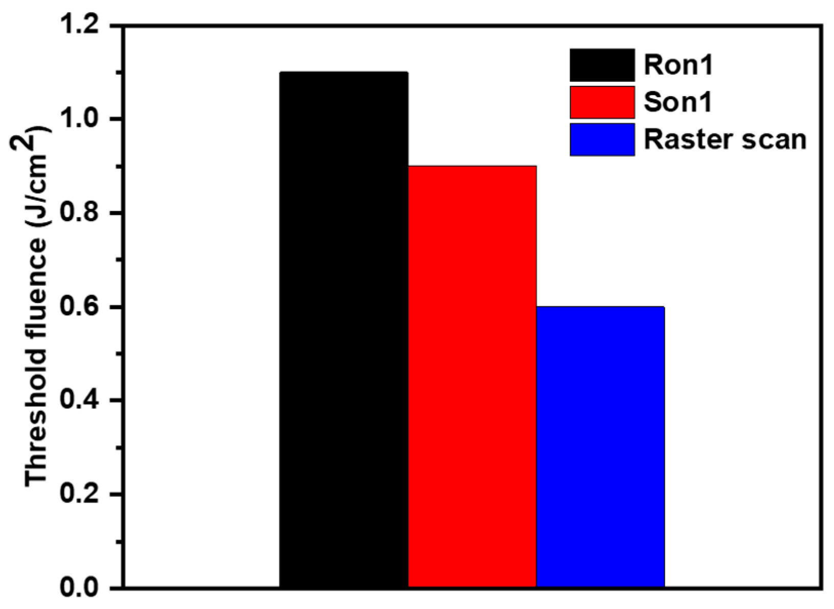
5. Discussion and Conclusions

In some of the MLD coatings, we found that the damage threshold is significantly lowered by accumulation effects due to the exposure of a consequent number of pulses and the presence of the defects in the coating [35,37,39]. As we mentioned earlier, 100k-on-1 tests can account for the accumulation effects substantially. The coating non-uniformity clusters and the presence of defects in the coating can be revealed in the Raster Scan method. The comparison of damage thresholds from different test methods can provide insights into the dominating damage mechanisms for the optical failure.
In order to validate the critical mechanisms behind the failure of the coating, we compared the threshold values by different test methods on the sample surface in Figure 7. It is clear from Figure 7 that the R-on-1 method has a high threshold value (1.1 J/cm2) compared to the other two test methods S-on-1 (0.9 J/cm2) and Raster Scan (0.6 J/cm2). This is because of its exposure to a lower number of pulses at a given fluence during the ramping. The different damage threshold values based on the test method are linked to the various interrogation methods involved in each method. Interestingly, the damage threshold values of R-on-1 and S-on-1 at an equal number of pulses are found to be consistent. This also implies that there were no laser conditioning effects by fs laser irradiation. If we compare the threshold values from the Raster Scan and 100k-on-1 methods, the Raster Scan method resulted in a lower damage threshold. This lower threshold value and localized damage in Figure 5 are clear indications of possible defects/weaker areas of the coating.
Recently, it was reported that non-uniformities in the stoichiometry, i.e., sub-stoichiometry of the thin film can be a precursor for laser damage [41]. The sub-stoichiometry in some parts of the coating can be created by producing more oxygen vacancies due to the higher exposure times to energetic Ar neutrals in IBS coating. The location-dependent oxygen deficiency defects can be possible in IBS/ion-bombardment-based deposition coatings. Therefore, the Raster Scan method can expose even the weaker features of the coating, so it can be reliably used to estimate the damage threshold for the tested MLD mirror compared to the multi-pulse S-on-1 test. Additionally, the lower threshold in the Raster Scan method compared to the 100k-on-1 perhaps indicates that the non-uniform coating defect clusters in optical coating can be a major limitation compared to the fatigue effects. The damage onset at the isolated defects for various tested MLD coatings revealed by the Raster Scan method in the picosecond regime was also reported [42]. However, we observed the catastrophic-type large area damage in the fs regime rather than the localized pin-point type damaged morphologies which were commonly observed in picosecond and nanosecond regimes [42,43]. This contrasting behavior in the fs regime could be linked to the deterministic damage behavior.
In the 100k-on-1 test method, we also observed that the catastrophic damage formation is quite deterministic. There is, however, a narrow fluence range of laser-induced permanent stress. The faint changes on the surface of the coating (see Figure 4b–d) are attributed to laser-induced stress since they are only visible in the Nomarski microscope. As the sample is coated with the IBS deposition method, the tested sample is expected to have densified coating layers and a high internal stress. The laser-induced stress can be higher or even lower than the internal stress of the coating, as our metrology could not differentiate between them. This laser-induced stress appeared as soft damage but still treated it as a damaged spot.
In conclusion, we reported various types of femtosecond laser damage in multilayer dielectric coatings by analyzing the damaged morphologies. It was found that the spatial features of the damaged morphologies may potentially indicate the involved damage mechanisms. We examined the laser-induced damage resistance of a hybrid dielectric mirror by different test methods. As each test method accounts for different mechanisms, the comparison of the damage threshold by different test methods intrigues the critical mechanisms of the coating failure. The damage formation in a tested coating is found to be very deterministic and predominantly catastrophic. In order to assess the realistic performance limit of the tested coating, the scanning of larger areas was found to be crucial compared to the tests of incubation/fatigue effects. This detailed study emphasizes that the testing of LIDT by different test methods is essential in the fs regime to evaluate the mechanisms behind the coating failure. Therefore, this work has a potential impact in ultrashort high-power lasers and optical coating communities.

Author Contributions

Conceptualization, P.K.V; Methodology, P.K.V. and D.K.; Formal Analysis, P.K.V.; Investigation, P.K.V.; Resources, P.K.V., D.K., and B.R.; Data Curation, P.K.V; Writing-Original Draft Preparation, P.K.V; Writing-Review and Editing, P.K.V. and D.K.; Visualization, P.K.V.; Supervision, D.K.; Project Administration, B.R.; Funding Acquisition, D.K. and B.R. All authors have read and agreed to the published version of the manuscript.

Funding

This research is funded from the projects Extreme Light Infrastructure (CZ.02.1.01/0.0/0.0/15_008/0000162, CZ.1.05/1.1.00/02.0061, CZ.1.07/2.3.00/20.0091) and Advanced research using high intensity laser produced photons and particles from European Regional Development Fund (CZ.02.1.01/0.0/0.0/16_019/0000789).

Acknowledgments

The authors would like to acknowledge Laseroptik GmbH for providing the tested sample.

Conflicts of Interest

The authors declare no conflict of interest.

References

  1. Backus, S.; Durfee, C.G., III; Murnane, M.M.; Kapteyn, H.C. High power ultrafast lasers. Rev. Sci. Instrum. 1998, 69, 1207–1223. [Google Scholar] [CrossRef]
  2. Danson, C.N.; Haefner, C.; Bromage, J.; Butcher, T.; Chanteloup, J.-C.F.; Chowdhury, E.A.; Galvanauskas, A.; Gizzi, L.A.; Hein, J.; Hillier, D.I.; et al. Petawatt and exawatt class lasers worldwide. High Power Laser Sci. Eng. 2019, 7, 1–54. [Google Scholar] [CrossRef]
  3. Mourou, G. Nobel Lecture: Extreme light physics and application. Rev. Mod. Phys. 2019, 91, 030501. [Google Scholar] [CrossRef]
  4. Rus, B.; Bakule, P.; Kramer, D.; Korn, G.; Green, J.T.; Nóvak, J.; Fibrich, M.; Batysta, F.; Thoma, J.; Naylon, J.; et al. ELI-Beamlines laser systems: Status and design options. In Proceedings of the SPIE 87801, High-Power, High-Energy, and High-Intensity Laser Technology; and Research Using Extreme Light: Entering New Frontiers with Petawatt-Class Lasers, 87801T, Prague, Czech Republic, 7 May 2013; SPIE: Bellingham, WA, USA, 2013. [Google Scholar]
  5. Rus, B.; Bakule, P.; Kramer, D.; Naylon, J.; Thoma, J.; Green, J.T.; Antipenkov, R.; Fibrich, M.; Novák, J.; Batysta, F.; et al. ELI-Beamlines: Development of next generation short-pulse laser systems. In Proceedings of the SPIE 95150; Research Using Extreme Light: Entering New Frontiers with Petawatt-Class Lasers II, 95150F, Prague, Czech Republic, 12 May 2015; SPIE: Bellingham, WA, USA, 2015. [Google Scholar]
  6. Rus, B.; Bakule, P.; Kramer, D.; Naylon, J.; Thoma, J.; Fibrich, M.; Green, J.T.; Lagron, J.C.; Antipenkov, R.; Bartoníček, J.; et al. ELI-Beamlines: Progress in development of next generation short-pulse laser systems. In Proceedings of the SPIE 10241; Research Using Extreme Light: Entering New Frontiers with Petawatt-Class Lasers III, 102410J, Prague, Czech Republic, 26 June 2017; SPIE: Bellingham, WA, USA, 2017. [Google Scholar]
  7. Mourou, G.A.; Barty, C.P.; Perry, M.D. Ultrahigh-Intensity Lasers: Physics of the Extreme on a Tabletop. Phys. Today 1998, 51, 22–28. [Google Scholar] [CrossRef]
  8. Salamin, Y.I.; Hu, S.X.; Hatsagortsyan, K.Z.; Keitel, C.H. Relativistic high-power laser–matter interactions. Phys. Rep. 2006, 427, 41–155. [Google Scholar] [CrossRef]
  9. Malka, V.; Fritzler, S.; Lefebvre, E.; Aleonard, M.M.; Burgy, F.; Chambaret, J.P.; Chemin, J.F.; Krushelnick, K.; Malka, G.; Mangles, S.P.D.; et al. Electron acceleration by a wake field forced by an intense ultrashort laser pulse. Science 2002, 298, 1596–1600. [Google Scholar] [CrossRef] [PubMed]
  10. Snavely, R.A.; Key, M.H.; Hatchett, S.P.; Cowan, T.E.; Roth, M.; Phillips, T.W.; Stoyer, M.A.; Henry, E.A.; Sangster, T.C.; Singh, M.S.; et al. Intense high-energy proton beams from petawatt-laser irradiation of solids. Phys. Rev. Lett. 2000, 85, 2945. [Google Scholar] [CrossRef] [PubMed]
  11. Remington, B.A.; Arnett, D.; Paul, R.; Takabe, H. Modeling astrophysical phenomena in the laboratory with intense lasers. Science 1999, 284, 1488–1493. [Google Scholar] [CrossRef]
  12. Bulanov, S.V.; Khoroshkov, V.S. Feasibility of using laser ion accelerators in proton therapy. Plasma Phys. Rep. 2002, 28, 453–456. [Google Scholar] [CrossRef]
  13. Seres, J.; Seres, E.; Verhoef, A.J.; Tempea, G.; Streli, C.; Wobrauschek, P.; Yakovlev, V.; Scrinzi, A.; Spielmann, C.; Krausz, F. Source of coherent kiloelectronvolt X-rays. Nature 2005, 433, 596. [Google Scholar] [CrossRef] [PubMed]
  14. Guo, T.; Spielmann, C.; Walker, B.C.; Barty, C.P.J. Generation of hard x rays by ultrafast terawatt lasers. Rev. Sci. Instrum. 2001, 72, 41–47. [Google Scholar] [CrossRef]
  15. Schiltz, D.; Patel, D.; Baumgarten, C.; Reagan, B.A.; Rocca, J.J.; Menoni, C.S. Strategies to increase laser damage performance of Ta2O5/SiO2 mirrors by modifications of the top layer design. Appl. Opt. 2017, 56, C136–C139. [Google Scholar] [CrossRef] [PubMed]
  16. Apfel, J.H. Optical coating design with reduced electric field intensity. Appl. Opt. 1977, 16, 1880–1885. [Google Scholar] [CrossRef] [PubMed]
  17. Gallais, L.; Commandré, M. Laser-induced damage thresholds of bulk and coating optical materials at 1030 nm, 500 fs. Appl. Opt. 2014, 53, A186–A196. [Google Scholar] [CrossRef]
  18. Mangote, B.; Gallais, L.; Commandré, M.; Mende, M.; Jensen, L.; Ehlers, H.; Jupé, M.; Ristau, D.; Melninkaitis, A.; Mirauskas, J.; et al. Femtosecond laser damage resistance of oxide and mixture oxide optical coatings. Opt. Lett. 2012, 37, 1478–1480. [Google Scholar] [CrossRef] [Green Version]
  19. Papernov, S. Defect-induced damage. In Laser-Induced Damage in Optical Materials; Ristau, D., Ed.; CRC Press: Boca Raton, FL, USA, 2014; pp. 25–73. [Google Scholar]
  20. Jasapara, J.; Nampoothiri, A.V.V.; Rudolph, W.; Ristau, D.; Starke, K. Femtosecond laser pulse induced breakdown in dielectric thin films. Phys. Rev. B 2001, 63, 045117. [Google Scholar] [CrossRef]
  21. Negres, R.A.; Stolz, C.J.; Thomas, M.D.; Caputo, M. 1064-nm, nanosecond laser mirror thin film damage competition. In Proceedings of the SPIE 10805, Laser-Induced Damage in Optical Materials 2018: 50th Anniversary Conference, Boulder, CO, USA, 16 November 2018; SPIE: Bellingham, WA, USA, 2018. [Google Scholar]
  22. Stolz, C.J.; Negres, R.A. Ten-year summary of the Boulder Damage Symposium annual thin film laser damage competition. Opt. Eng. 2018, 57, 121910. [Google Scholar] [CrossRef]
  23. Ristau, D. Laser-Induced Damage in Optical Materials; CRC Press: Boca Raton, FL, USA, 2014. [Google Scholar]
  24. ISO 21254-1:2011, Lasers and Laser-Related Equipment—Test Methods for Laser-Induced Damage Threshold—Part 1: Definitions and General Principles; ISO: Geneva, Switzerland, 2011.
  25. Stuart, B.C.; Feit, M.D.; Herman, S.; Rubenchik, A.M.; Shore, B.W.; Perry, M.D. Nanosecond-to-femtosecond laser-induced breakdown in dielectrics. Phys. Rev. B 1996, 53, 1749. [Google Scholar] [CrossRef] [Green Version]
  26. Guizard, S.; Klimentov, S.; Mouskeftaras, A.; Fedorov, N.; Geoffroy, G.; Vilmart, G. Ultrafast Breakdown of dielectrics: Energy absorption mechanisms investigated by double pulse experiments. Appl. Surf. Sci. 2015, 336, 206–211. [Google Scholar] [CrossRef]
  27. Velpula, P.K.; Bhuyan, M.K.; Courvoisier, F.; Zhang, H.; Colombier, J.P.; Stoian, R. Spatio-temporal dynamics in nondiffractive Bessel ultrafast laser nanoscale volume structuring. Laser Photonics Rev. 2016, 10, 230–244. [Google Scholar] [CrossRef]
  28. Ashkenasi, D.; Lorenz, M.; Stoian, R.; Rosenfeld, A. Surface damage threshold and structuring of dielectrics using femtosecond laser pulses: The role of incubation. Appl. Surf. Sci. 1999, 150, 101–106. [Google Scholar] [CrossRef]
  29. Chmel, A.E. Fatigue laser-induced damage in transparent materials. Mater. Sci. Eng. B 1997, 49, 175–190. [Google Scholar] [CrossRef]
  30. Gallais, L.; Natoli, J.Y.; Amra, C. Statistical study of single and multiple pulse laser-induced damage in glasses. Opt. Express 2002, 10, 1465–1474. [Google Scholar] [CrossRef] [PubMed]
  31. Merkle, L.D.; Koumvakalis, N.; Bass, M. Laser-induced bulk damage in SiO2 at 1.064, 0.532, and 0.355 μm. J. Appl. Phys. 1984, 55, 772–775. [Google Scholar] [CrossRef]
  32. Kitriotis, D.; Merkle, L.D. Multiple pulse laser-induced damage phenomena in silicates. Appl. Opt. 1989, 28, 949–958. [Google Scholar] [CrossRef]
  33. Hildenbrand, A.; Wagner, F.R.; Akhouayri, H.; Natoli, J.Y.; Commandre, M.; Théodore, F.; Albrecht, H. Laser-induced damage investigation at 1064 nmin KTiOPO 4 crystals and its analogy with RbTiOPO 4. Appl. Opt. 2009, 48, 4263–4269. [Google Scholar] [CrossRef]
  34. O’Connell, R.M.; Deaton, T.F.; Saito, T.T. Single-and multiple-shot laser-damage properties of commercial grade PMMA. Appl. Opt. 1984, 23, 682–688. [Google Scholar] [CrossRef]
  35. Velpula, P.K.; Ďurák, M.; Kramer, D.; Meadows, A.R.; Vilémová, M.; Rus, B. Evolution of femtosecond laser damage in a hafnia–silica multi-layer dielectric coating. Opt. Lett. 2019, 44, 5342–5345. [Google Scholar] [CrossRef]
  36. McDonald, J.P.; Mistry, V.R.; Ray, K.E.; Yalisove, S.M.; Nees, J.A.; Moody, N.R. Femtosecond-laser-induced delamination and blister formation in thermal oxide films on silicon (100). Appl. Phys. Lett. 2006, 88, 153121. [Google Scholar] [CrossRef] [Green Version]
  37. Ďurák, M.; Kramer, D.; Velpula, P.K.; Meadows, A.R.; Cupal, J.; Rus, B. Comparison of different LIDT testing protocols for PW and multi-PW class high-reflectivity coatings. In Proceedings of the SPIE 10014, Laser-Induced Damage in Optical Materials 2016, Boulder, CO, USA, 6 December 2016; SPIE: Bellingham, WA, USA, 2016. [Google Scholar]
  38. ISO 21254-2:2011 Lasers and Laser-Related Equipment—Test Methods for Laser-Induced Damage Threshold—Part 2: Threshold Determination; ISO: Geneva, Switzerland, 2011.
  39. Ďurák, M.; Velpula, P.K.; Kramer, D.; Cupal, J.; Medřík, T.; Hřebíček, J.; Golasowski, J.; Peceli, D.; Kozlová, M.; Rus, B. Laser-induced damage threshold tests of ultrafast multilayer dielectric coatings in various environmental conditions relevant for operation of ELI beamlines laser systems. Opt. Eng. 2016, 56, 011024. [Google Scholar] [CrossRef]
  40. Wolfe, C.R.; Kozlowski, M.R.; Campbell, J.H.; Rainer, F.; Morgan, A.J.; Gonzales, R.P. Laser conditioning of optical thin films. In Proceedings of the SPIE 1438, Laser-Induced Damage in Optical Materials 1989; Bennett, H.E., Chase, L.L., Guenther, A.H., Newnam, B.E., Soileau, M.J., Eds.; SPIE: Bellingham, WA, USA, 2016; pp. 360–375. [Google Scholar]
  41. Harthcock, C.; Qiu, S.R.; Mirkarimi, P.B.; Negres, R.A.; Guss, G.; Menor, M.G.; Bhowmik, G.; Huang, M. Origin and effect of film sub-stoichiometry on ultraviolet, ns-laser damage resistance of hafnia single layers. Opt. Mater. Express 2020, 10, 937–951. [Google Scholar] [CrossRef]
  42. Negres, R.A.; Carr, C.W.; Laurence, T.A.; Stanion, K.; Guss, G.; Cross, D.A.; Wegner, P.J.; Stolz, C.J. Laser-induced damage of intrinsic and extrinsic defects by picosecond pulses on multilayer dielectric coatings for petawatt-class lasers. Opt. Eng. 2016, 56, 011008. [Google Scholar] [CrossRef]
  43. Batavičiūtė, G.; Ščiuka, M.; Melninkaitis, A. Direct comparison of defect ensembles extracted from damage probability and raster scan measurements. J. Appl. Phys. 2015, 118, 105306. [Google Scholar] [CrossRef]
Figure 1. Various types of femtosecond laser damage morphologies (ai) on the surface of Multi-layer dielectric (MLD) optical coatings.
Coatings 10 00603 g001
Figure 2. Schematic experimental setup of laser-induced damage resistance measurements. λ/2: half-wave plate, TFP: thin-film polarizer, RGA: residual gas analyzer and Cam: Camera.
Coatings 10 00603 g002
Figure 3. (a) Incident laser fluence on the sample surface vs. number of laser pulses for 100k-on-1. (b) The damage probability vs. the laser fluence on the sample surface at 45 deg Angle of Incidence (AOI).
Coatings 10 00603 g003
Figure 4. The laser-induced damage growth on the surface of the MLD coating is shown for laser fluence increasing from (bg). The image (a) is a Nomarski microscope image and corresponding enhanced contrast image is shown in (d). The image (d) is highlighting the invisible features in (a) at 1.04 J/cm2. The similar enhanced contrast bright field images are shown in images (b,c).
Coatings 10 00603 g004
Figure 5. Typical surface damage morphologies of the Raster Scan for a tested MLD coating with laser fluence increasing from (ac).
Coatings 10 00603 g005
Figure 6. The sample evolution of the R-on-1 test (fluence vs. time) is shown in (a) for a tested MLD coating. (b) Shows the damage probability over several sites vs. R-on-1 damage threshold fluence on the sample surface at 45 deg AOI.
Coatings 10 00603 g006
Figure 7. The comparison of damage threshold fluence values on the sample surface by three test methods.
Coatings 10 00603 g007
Table 1. Parameters of the tested MLD coating.
Coating MaterialsCoating MethodHR Central Wavelength at 45 degHR Bandwidth for S-polAngle of Incidence Used for LIDT TestsGDD
Ta2O5/HfO2/SiO2IBS800 nm180 nm45 deg≤ 20 fs2

