Abstract
Recently, research has been conducted on nanocomposite thin films containing new additive elements in ZrN. In this paper, a method for depositing ZrCuSiN nanocomposite coatings using a ZrCuSi single target is presented. The ZrCuSi target that was used to easily deposit a ZrCuSiN coating in a mixed gas atmosphere (Ar + N2) was produced by a simple arc melting method (casting process). The effect of the nitrogen content was investigated by depositing a ZrCuSiN coating using alloy targets at various nitrogen gas flow rates (2, 4, 6, and 8 sccm). X-ray diffraction analysis of the ZrCuSiN coatings revealed a ZrN structure with a preferable orientation (200). As the nitrogen flow rate increased, the formation of o-Zr3N4 was dominant in the ZrN formation. A nitrogen gas flow rate of 4 sccm produced a coating with optimal ZrN and a-Si3N4 coordination and maximum hardness (41 GPa). Reciprocal friction tests of all coatings and uncoated carburized SCM415 steel in a 5W30 lubrication atmosphere demonstrated that the 4 sccm coating had the lowest friction coefficient (0.002). Therefore, our method has the potential to be an alternative surface coating technique for materials used in automotive engine parts and various other wear protection applications.
1. Introduction
The hardness and abrasion resistance of transition metal nitride films, specifically hard coatings including TiN, CrN, and ZrN, have been widely investigated [1,2,3]. ZrN coatings tend to be favored over TiN coatings in industrial applications due to their superior mechanical properties and corrosion resistance. The nanocrystalline composites of ZrN with added elements have gained attention from researchers for the development of ZrN coatings with improved properties. ZrCuN- and ZrSiN-based coatings have been of particular interest [4,5,6,7]. The addition of copper, a soft metal, to ZrN can increase toughness and hardness, while the addition of silicon, a non-metal, results in excellent thermal stability, oxidation resistance, abrasion resistance, and friction characteristics [8]. The ZrCuN coating has an nc-ZrN/Cu structure consisting of a hard and soft phase. The Cu content in the ZrCuN coating is essential to form a hard film. Additionally, when the composition of Cu at the ZrCu target is 10%, the hardness of the deposited ZrCuN coating is at least 40 GPa [9]. In contrast, the excellent properties of ZrSiN coatings are attributable to the formation of an amorphous phase (a–Si3N4); however, the addition of large amounts of Si degrades the mechanical properties of the resulting coating. The highest hardness and friction characteristics of ZrSiN coatings are exhibited at 4%–8% [7,8]. Most studies of ZrCuN and ZrSiN coatings focus on the change in mechanical properties due to the separate addition of Cu and Si. To date, a ZrCuSiN coating containing both Cu and Si has not been reported.
In the manufacture of a multi-component alloy film, different targets corresponding to the different components are often required. The deposition of coatings by a co-sputtering method requires control of various parameters and entails high process costs. Alternatively, for deposition using a multi-component single target, the intended composition of the coating layer can be easily obtained without the use of complex equipment and processes given that the target composition can be transferred to the coating layer. Additionally, if the coating layer has enough toughness, there is no need to increase thin film adhesion by replacing the deposition buffer layer with another material. This is because the buffer layer can only be deposited through a controlled argon atmospheric gas that is homogeneous across targets. This atmosphere-dependent deposition allows for a more advantageous, simplified, and low-cost coating process [10].
To commercialize the developed coating, it is imperative not only that the sputtering method used is simple but also that the composition difference between the deposited film and the target core material is small. Deposition of coatings by a multi-component single target with a grain size below the micrometer range meets these requirements [11]. The multi-component single targets can be manufactured by casting and powder metallurgy [12]. The formation of sputter targets by casting is the simplest fabrication although composition design of the target is crucial.
This paper is the first to report the composition of ZrCuSi that can produce a ZrCuSi multi-component single target using arc melting (a type of casting method) and use the resulting target for ZrCuSiN coating. We successfully synthesized ZrCuSi with varying levels of Si and consequently utilized the resulting materials to deposit ZrCuSiN under various nitrogen gas ratios and in an argon–nitrogen mixed gas environment. Finally, the microstructure and friction properties of the resulting coatings were evaluated.
2. Materials and Methods
2.1. ZrCuSi Alloy Single Target Manufacturing and Analysis
ZrCuSi was prepared by melting Zr, Cu, and Si in an arc melting furnace under an argon atmosphere. Since ZrCuSi alloys have a high formability of amorphous phase, the four compositions were selected around the binary and ternary eutectic points in the Zr–Cu–Si system. Four ZrCuSi ingots were developed, namely Alloy 4.5 (Zr82Cu13.5Si4.5), Alloy 5.5 (Zr84.1Cu10.4Si5.5), Alloy 6.5 (Zr86.3Cu7.2Si6.5), and Alloy 7.5 (Zr88.4Cu4.1Si7.5). All ingots were melted and flipped several times to ensure that the samples were chemically homogeneous. The resulting ingots were processed to produce round targets (diameter = 12.7 cm; thickness = 0.8 cm). A Rockwell hardness tester was used to measure the hardness and toughness of the manufactured ZrCuSi targets with a load of 150 kgf. Ten parts of the target were selected and prepared as samples. These samples were investigated to determine the homogeneity of the microstructure, and the composition of the different types of ingots.
2.2. Coating Deposition
The ZrCuSiN coating was synthesized by a single target fabricated by the arc melting method. This coating was deposited on a Si wafer and on a carburized SCM415 steel circular specimen (diameter = 12 mm), using a DC magnetron sputtering system. For this experiment, only Alloy 6.5, which had the best mechanical properties, was used from among the four compositions (Alloy 4.5, Alloy 5.5, Alloy 6.5, and Alloy 7.5). The distance between the ZrCuSi target and the substrate was maintained at 120 mm. Prior to deposition, the samples were ultrasonically cleaned using an ethanol solution for 10 min. To remove contamination on the substrate surface, the substrate was continuously cleaned for 30 min using Ar-ion bombardment with a DC pulse discharge (Us = 600 V, PAr = 1.2 Pa, Is = 0.02 A). Nitrogen gas flow rates of 2, 4, 6, and 8 sccm were used, and the argon–nitrogen gas flow rate was constant at a total of 24 sccm. Power density (9.8 W/cm2), base pressure (1.5 × 10⁻⁵ Pa), process pressure (0.66 Pa), and deposition time (30 min) were fixed. Before deposition of the coating under a nitrogen atmosphere, the buffer layer was deposited in the same target in an argon atmosphere for 10 min to improve adhesion between the coating and the specimen.
2.3. Microstructure Analysis
For microstructural analysis of the ZrCuSiN coating, a coating deposited on a silicon wafer was used. The crystal structures of ZrCuSiN coatings were confirmed using X-ray diffraction (XRD, DMAX-2500, Rigaku, Tokyo, Japan, 2001, 40 kV and 40 mA). The surface hardness and elastic modulus of the coatings were measured using a nano-indenter (HM2000, Fischer Technology, Windsor, CT, USA), and the maximum indentation depth was controlled to less than 10% of the film thickness (about 100–200 nm) to avoid substrate effects. A flat indenter was used to measure the load, and the load application time was 20 s. The surface morphology and roughness of the coating were observed by atomic force microscopy (AFM, Picoplus 2500, Shanghai, China).
2.4. Friction Test of Coating
The friction and wear behaviors of ZrCuSiN coatings were evaluated using a reciprocating sliding wear test, which was conducted using an STM-7 (Hanmi Industries Ltd., Seoul, Korea). The FC25 plate counter was stationary in the test machine, and the ZrCuSiN coating was subjected to oscillating motion. All experiments were performed in a gasoline engine oil lubrication environment with oil additives (Turbo SYN gasoline engine oil, Hyundai Mobis, Seoul, Korea). The test was performed with fixed values of load (100 N), speed (10 Hz), and time (60 min). After the friction test, the specimen was examined using an optical microscope to evaluate the damage on the surface.
3. Results and Discussion
Varying levels of Zr–Cu and Zr–Si were investigated to find the optimal combination (Figure 1a). The compositions of the various ternary ZrCuSi targets prepared by arc melting are summarized in Table 1. Each sample was denoted by Alloy 4.5–7.5 depending on its corresponding Si content. Figure 1b shows the XRD analysis results of the manufactured targets. The target of Alloy 4.5 showed the sharpest peak, which corresponded to a large grain size. As the Si content further increased, a broader peak was observed. Zr2Cu and ZrCu peaks were present in Alloys 4.5–6.5, and Zr2Cu and Zr2Si peaks could be identified in Alloy 7.5. As seen on the back scattered electron (BSE) image of manufactured targets, the alloy with a Si content of 4.5% (Alloy 4.5) possessed a large grain size (Figure 1c). The smallest particles were found in Alloy 6.5. When the Si content increased to 7.5, an increase in particle size was observed, possibly due to the formation of Zr2Si. To investigate the hardness and the toughness of the manufactured materials, an indentation test was performed using the Rockwell hardness method with a load of 30 kg. The hardness values of Alloy 4.5, 5.5, 6.5, and 7.5 were confirmed to be 321, 307, 326, and 339 HV, respectively. No cracks were found in all the targets.
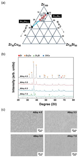
Figure 1.
(a) Compositional design of Zr–Cu–Si target. (b,c) Analysis of manufactured targets prepared by arc melting. (b) XRD peak of ZrCuSi targets. (c) Surface BSE images of the prepared ZrCuSi targets.

Table 1.
Compositions of designed alloys fabricated by arc melting (at.%) a.
The production of a Zr-based amorphous alloy target has been reported only in the literature [11]. In the aforementioned study, the characteristics of the target and deposited coating were found to be best when the crystal size of a single target was less than 0.5 μm. Furthermore, heat treatment was required to produce fine crystalline targets. Alternatively, the composition under investigation in our study can be used to produce targets with a fine grain size using an inexpensive arc melting preparation method. Alloy 6.5’s target was found to be optimal, with the smallest grain size and outstanding hardness and toughness. This alloy was successfully deposited by magnetron sputtering for long periods of time. The coating was deposited in various mixed-gas atmosphere levels (Ar:N2), and the effects of nitrogen gas flow on the composition of the ZrCuSiN film was investigated using energy dispersive X-ray spectroscopy (EDS) (Figure 2a). The thickness of the deposited coatings was about 2 μm. When nitrogen gas was increased from 2 sccm to 8 sccm, Zr showed the greatest change, with a measured decrease from 66% to 41%. Only slight changes in Cu and Si composition were observed. This was due to the formation of Zr–N bonds as the nitrogen flow rate increased, and the elemental Zr composition appeared to have a stoichiometric decrease. The surface roughness changes of the ZrCuSiN coatings in various N2 gas flows were evaluated using AFM (Figure 2b). Surface roughness is closely related to film structure, and directly depends on the size and orientation of the crystals. The uncovered Si wafer showed an average roughness (Rq) of about 0.15 to 0.2 nm. When the nitrogen gas flow rate was 2, 4, 6, and 8 sccm, the surface roughness (Rq) of the coatings was 0.211, 1.182, 0.347, and 0.147 nm, respectively. Peak roughness of 1.182 nm was observed at 4 sccm, which was smoothed when the nitrogen gas flow was further increased. It is well documented that the changes in the surface roughness of the coating are related to crystal orientation, particle size, and structure density. Previous studies have shown that the surface of the coating is smoother when subjected to high nitrogen gas flows [13].
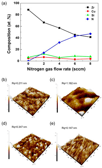
Figure 2.
(a) Composition of ZrCuSiN coatings deposited at different N2 gas flows. (b,e) 3D AFM images of the ZrCuSiN coatings deposited at different nitrogen gas flows: (b) 2 sccm, (c) 4 sccm, (d) 6 sccm, and (e) 8 sccm.
The XRD pattern of the deposited ZrN-based coating is shown in Figure 3a. In general, the ZrN film exhibited a face-centered cubic (fcc) NaCl structure with multiple orientations of (111), (200), (220), (311), and (222) crystal planes (Reference pattern ICDD PDF 35-0753). The XRD pattern for the ZrCuSiN coating was identified as a single broad band at 2 sccm, which corresponded to a typical peak for an amorphous structure. This suggests that the nitrogen content was not sufficient to form the nitride phases. At 4 and 6 sccm of nitrogen flow, ZrCuSiN coatings included a preferred (200) orientation of the ZrN crystals. These changes in grain growth have been reported in Me–Si–N systems (Me = Ti, Zr, W, V, Cr, Mo, and Ta, which are all transition metals) [14]. Most of the transition metal nitride phases show full immiscibility of the MeN phase with silicon [15]. However, the incorporation of silicon atoms in the MeN fcc lattice can result in a change in crystal growth [16,17]. A broad reflection peak observed between 2° to 35.2° (obtained at 8 sccm), and close to the position of the (320) and (042) peaks, was related to o-Zr3N4 [18]. At high nitrogen gas flow rates, the crystallization of the structure of the ZrCuSiN coating was incomplete.
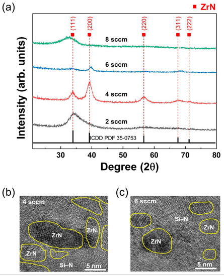
Figure 3.
(a) XRD patterns of the ZrCuSiN coatings deposited at different N2 gas flow rates. (b,c) TEM images of the ZrCuSiN coatings deposited at different nitrogen gas flows: (b) 4 sccm; (c) 6 sccm.
A transmission electron microscopy (TEM) analysis of the microstructure of the 4 and 6 sccm ZrCuSiN coatings confirmed the XRD findings and clearly showed the nc microstructure of the nanocomposite (Figure 3b,c). The grain size of ZrN in the coatings was found to be ca. 10 nm for the 4 sccm coating and ca. 5 nm for 6 sccm. These ZrN nanocrystals exhibited an encapsulation structure and were distributed across the amorphous phase. This amorphous phase consisting of amorphous silicon nitride (a–Si3N4) resulted from the addition of Si into ZrN. This phenomenon has been observed in other MeXN (X = Cu, Cr, Ag, Ni, or Sn) coatings [19,20,21]. The microstructure identified in the 4 and 6 sccm coatings closely matched the concept of a nanocomposite structure proposed by Veprek [22].
Even when added in very small amounts, Cu and Si exhibited the same mechanism of covering ZrN particles to prevent ZrN growth. When a small amount of Cu was added, most of the Cu was either included in the ZrN grains or was randomly located at a defect site (e.g., grain boundaries). The incorporation of Cu is difficult to confirm using only TEM images [23]. Therefore, X-ray photoelectron spectroscopy (XPS) was performed for additional analysis of the phase identified using TEM. XPS analysis for the chemical bonding of Zr, Cu, Si, and N elements was conducted on the coating under a nitrogen gas flow rate of 4 sccm (Figure 4). A C1 peak of 284.6 eV was used to correct the XPS spectra [24]. Four peaks related to Zr 3d were observed (Figure 4a). The prominent peaks that appeared at 180.9 and 183.3 eV covered a substantial curve area corresponding to ZrN [25]. The ZrO2 oxide phase was assigned to the peaks at 181.7 and 184.1 eV. These observations were almost identical to previously reported values [26]. The Zr–N bond was formed during a reaction with the N2 atmosphere gas, while the Zr–O bond was formed due to the influence of small amounts of oxygen present either in the target or in the chamber. Based on thermochemical data of zirconium oxides and nitrides, the formation of Zr–O was more energetically advantageous than Zr–N (: −1100.6, : –365.5 kJ/mol) [27]. Therefore, ZrO2 was readily formed and found in thin films even in the presence of small amounts of oxygen.
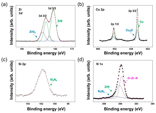
Figure 4.
XPS profiles for ZrCuSiN coatings at 4 sccm. (a) Zr, (b) Cu, (c) Si, and (d) N.
Cu and Cu2O bonds were attributed to 932.4 eV and 933.6 eV, respectively [24]. Cu–O bonds were readily formed due to a similar reaction to Zr–O. In the N 1s spectrum, prominent peaks were observed due to the presence of bonds such as O–Zr–N (395.8 eV), ZrN (396.6 eV), and Si3N4 (397.4 eV) [28,29]. The Si 2p spectrum was separated into multiple peaks as nitrogen increased. At 4 sccm, the main peak located at 101.8 eV corresponded to Si3N4, confirming that the amorphous phase identified in TEM was a-Si3N4 [20,30,31]. The heat of formation of Si3N (= −745.1 kJ/mol) was more negative than that of ZrN (= −365.5 kJ/mol), and α–Si3N4 bonds were formed earlier than ZrN bonds in the reactive N2 atmosphere [32,33]. Both XPS and TEM results confirmed that amorphous Si3N4 formed first and subsequently encapsulated the ZrN crystal to limit crystal growth.
The changes in hardness (H) and elastic modulus (E) of the ZrCuSiN coating were investigated at various N2 gas flow rates (Figure 5a). The coating was measured under a maximum load of 10 mN and at an indentation depth of less than 10% of the coating thickness. As the nitrogen gas flow increased, the ZrCuSiN coatings exhibited highest hardness (40 GPa) at 4 sccm, with a subsequent decrease of hardness with increase of nitrogen. This maximum hardness value observed in the 4 sccm coating was a result of the formation of nc-ZrN and its uniform distribution in the a-Si3N4 matrix. Very small crystals (≤10 nm) separated by an amorphous matrix (a-Si3N4, Cu) behave differently than conventional materials (generally with particles larger than 100 nm). The nc hard coating can be made harder with either appropriate microstructure design or with an increased grain boundary complexity (grain boundary strengthening). a-Si3N4 is known to be an important factor in increasing the hardness of MeSiN coatings by preventing cracking along grain boundaries [18,34]. The properties of nanocomposites strongly depend on the volume fraction of the amorphous matrix, and hard nanocomplex coatings generally have the highest hardness at a nanocrystal size in the range of 1–3 nm [19,34]. In contrast, further increasing the volume fraction of amorphous Si3N4 in the ZrN-based coating decreases the hardness of the coating [7]. The hardness decreases at 6 sccm were accompanied by a decrease in crystal size and an increase in the amorphous phase, as confirmed by the TEM analysis. The rapid hardness drops at 8 sccm were due to the formation of both an amorphous phase and an unstable o-Zr3N4 phase.
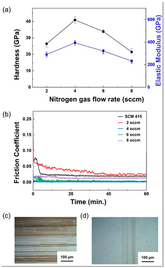
Figure 5.
(a) Effects of N2 gas flow on the hardness and elastic modulus of ZrCuSiN at different N2 gas flow rates. (b) Friction coefficient of ZrCuSiN coatings deposited at different N2 gas flow rates. (c,d) Images of the coating surface after the friction test: (c) SCM 415, and (d) 4 sccm.
The friction–wear characteristics of ZrCuSiN coatings, produced at varying nitrogen flow rates and deposited on carburized SCM 415 circular disc specimens, were investigated using reciprocal friction tests under a 5W30 lubrication atmosphere (Figure 5b). Uncoated SCM 415 steel was used as a control. The 2, 4, 6, and 8 sccm nitrogen flow rate coatings exhibited friction coefficients of 0.025 (highest), 0.002 (lowest), 0.004, and 0.013, respectively, while the coefficient of friction of SCM 415 was 0.02 (Figure 5b). After the test, the surface of each specimen was observed using an optical microscope (Figure 5c,d). The SCM 415 surface was found to be severely abraded, while the 4 sccm coating was not. This observation can be attributed to the formation of a tribolayer (or a mechanically mixed layer) that protects the worn surface, which in turn lowers the wear rate. The mechanism of the lower friction coefficient of ZrCuSiN coating will be further investigated in future studies.
4. Conclusions
A simple arc melting method was used to produce a ZrCuSi alloy target. Using this alloy target, a ZrCuSiN coating was successfully deposited using magnetron sputtering under a range of different nitrogen flow rates. As a result, the homogeneous composition of the alloy target was transferred to the coating. This coating exhibited excellent mechanical properties, including a maximum hardness of 41 GPa, and minimum friction coefficient of 0.002 at 4 sccm nitrogen gas flow rate. This was regarded as the optimal ZrCuSiN coating in this study. The excellent properties of the coating were found to be related to the nc–ZrN/Cu/a–Si3N4 formed in the ZrCuSiN coating. The evaluation was done using TEM, XPS, and nano-indentation test results. The coating described in this study shows great potential for use in automobile engine parts, which require excellent wear resistance and low friction characteristics in harsh environments. The tribo-layer formation of ZrCuSi coatings that induce low frictional properties should be further investigated in future studies.
Author Contributions
Conceptualization, S.Y.S. and K.I.M.; formal analysis, H.W.Y.; writing—original draft preparation, H.W.Y.; review and editing, S.H.K. and K.I.M.; project administration, K.I.M. All authors have read and agreed to the published version of the manuscript.
Funding
This work was funded by the Technology Innovation Program (10063502, Development of advanced nano-micron coating material and coated cutting tool for Hard-to-Cut), which is in turn funded by the Ministry of Trade, Industry & Energy (MOTIE, Korea).
Conflicts of Interest
The authors declare no conflict of interest.
References
- Musil, J.; Vlček, J. Magnetron sputtering of films with controlled texture and grain size. Mater. Chem. Phys. 1998, 54, 116–122. [Google Scholar] [CrossRef]
- Soe, W.H.; Yamamoto, R. Mechanical properties of ceramic multilayers: TiN/CrN, TiN/ZrN, and TiN/TaN. Mater. Chem. Phys. 1997, 50, 176–181. [Google Scholar] [CrossRef]
- Milošev, I.; Strehblow, H.H.; Navinšek, B. Comparison of TiN, ZrN and CrN hard nitride coatings: Electrochemical and thermal oxidation. Thin Solid Films 1997, 303, 246–254. [Google Scholar] [CrossRef]
- Pilloud, D.; Pierson, J.F.; Marques, A.P.; Cavaleiro, A. Structural changes in Zr–Si–N films vs. their silicon content. Surf. Coat. Technol. 2004, 180, 352–356. [Google Scholar] [CrossRef]
- Musil, J.; Vlcek, J.; Zeman, P.; Setsuhara, Y.; Miyake, S.; Konuma, S.; Kumagai, M.; Mitterer, C. Morphology and microstructure of hard and superhard Zr–Cu–N nanocomposite coatings. Jpn. J. Appl. Phys. 2002, 41, 6529. [Google Scholar] [CrossRef]
- Zemana, P.; Čerstvý, R.; Mayrhofer, P.H.; Mitterer, C.; Musil, J. Structure and properties of hard and superhard Zr–Cu–N nanocomposite coatings. Mater. Sci. Eng. A 2000, 289, 189–197. [Google Scholar] [CrossRef]
- Choi, H.; Jang, J.; Zhang, T.; Kim, J.H.; Park, I.W.; Kim, K.H. Effect of Si addition on the microstructure, mechanical properties and tribological properties of Zr–Si–N nanocomposite coatings deposited by a hybrid coating system. Surf. Coat. Technol. 2014, 259, 707–713. [Google Scholar] [CrossRef]
- Nose, M.; Zhou, M.; Nagae, T.; Mae, T.; Yokota, M.; Saji, S. Properties of Zr–Si–N coatings prepared by RF reactive sputtering. Surf. Coat. Technol. 2000, 132, 163–168. [Google Scholar] [CrossRef]
- Musil, J.; Zeman, P.; Hrubý, H.; Mayrhofer, P.H. ZrN/Cu nanocomposite film—A novel superhard material. Surf. Coat. Technol. 1999, 120, 179–183. [Google Scholar] [CrossRef]
- Liu, Y.H.; Fujita, T.; Hirata, A.; Li, S.; Liu, H.W.; Zhang, W.; Inoue, A.; Chen, M.W. Deposition of multicomponent metallic glass films by single-target magnetron sputtering. Intermetallics. 2012, 21, 105–114. [Google Scholar] [CrossRef]
- Moon, K.I.; Lee, H.C.; Sun, J.H.; Lee, C.H.; Shin, S.Y. Development and Characterization of Zr-Based Multi-Component Nanocomposite Coatings Prepared Using Single Alloying Target. Adv. Eng. Mater. 2018, 20, 1700904. [Google Scholar] [CrossRef]
- Ohring, M. Materials Science of Thin Films, 2nd ed.; Academic Press: Sandie go, CA, USA, 2002; p. 206. [Google Scholar]
- Ali, F.; Park, B.S.; Kwak, J.S. The impact of surface morphology on TiAlN film’s properties. J. Ceram. Process. Res. 2013, 14, 529–534. [Google Scholar]
- Wu, Z.T.; Qi, Z.B.; Wei, B.B.; Zhang, D.F.; Wang, Z.C. Understanding hardness evolution of Zr–Si–N nanocomposite coatings via investigating their deformation behaviors. J. Eur. Ceram. Soc. 2016, 36, 3329–3339. [Google Scholar] [CrossRef]
- Rogl, P.; Schuster, J.C. Phase Diagrams of Ternary Boron Nitride and Silicon Nitride Systems; ASM International: Novelty, OH, USA, 1992. [Google Scholar]
- Vaz, F.; Rebouta, L.; Almeida, B.; Goudeau, P.; Pacaud, J.; Rivière, J.P.; Sousa, J.B. Structural analysis of Ti1–xSixNy nanocomposite films prepared by reactive magnetron sputtering. Surf. Coat. Technol. 1999, 120, 166–172. [Google Scholar] [CrossRef]
- Nah, J.W.; Hwang, S.K.; Lee, C.M. Development of a complex heat resistant hard coating based on (Ta, Si)N by reactive sputtering. Mater. Chem. Phys. 2000, 62, 115–121. [Google Scholar] [CrossRef]
- Vaz, F.; Martin, N.; Fenker, M. (Eds.) Metallic Oxynitride Thin Films by Reactive Sputtering and Related Deposition Methods: Process, Properties and Applications; Bentham Science Publishers: Sharjah, UAE, 2013; pp. 64–112. [Google Scholar]
- Daniel, R.; Musil, J. (Eds.) Novel Nanocomposite Coatings: Advances and Industrial Applications, 1st ed.; Jenny Stanford Publishing: Boca Raton, FL, USA, 2014; p. 100. [Google Scholar]
- Martin, P.J.; Bendavid, A.; Cairney, J.M.; Hoffman, M. Nanocomposite Ti–Si–N, Zr–Si–N, Ti–Al–Si–N, Ti–Al–V–Si–N thin film coatings deposited by vacuum arc deposition. Surf. Coat. Technol. 2005, 200, 2228–2235. [Google Scholar] [CrossRef]
- Patscheider, J.; Zehnder, T.; Diserens, M. Structure–performance relations in nanocomposite coatings. Surf. Coat. Technol. 2001, 146, 201–208. [Google Scholar] [CrossRef]
- Vepřek, S. Conventional and new approaches towards the design of novel superhard materials. Surf. Coat. Technol. 1997, 97, 15–22. [Google Scholar] [CrossRef]
- Audronis, M.; Jimenez, O.; Leyland, A.; Matthews, A. The morphology and structure of PVD ZrN–Cu thin films. J. Phys. D Appl. Phys. 2009, 42, 085308. [Google Scholar] [CrossRef]
- Moulder, J.F.; Chastain, J.; King, R.C. Handbook of X-ray Photoelectron Spectroscopy: A Reference Book of Standard Spectra for Identification and Interpretation of XPS Data; Physical Electronics: Chanhassen, MN USA, 1995; pp. 32–190. [Google Scholar]
- Badrinarayanan, S.; Sinha, S.; Mandale, A.B. XPS studies of nitrogen ion implanted zirconium and titanium. J. Electron. Spectrosc. Relat. Phenomena 1989, 49, 303–309. [Google Scholar] [CrossRef]
- Anderson, J.A.; Fierro, J.L.G. Bulk and surface properties of copper-containing oxides of the general formula LaZr1-xCuxO3. J. Solid State Chem. 1994, 108, 305–313. [Google Scholar] [CrossRef]
- Dean, J.A. Lange’s Handbook of Chemistry, 15th ed.; McGraw-Hill, Inc.: London, UK, 1999; pp. 936–943. [Google Scholar]
- Muneshwar, T.; Ken, C. Comparing XPS on bare and capped ZrN films grown by plasma enhanced ALD: Effect of ambient oxidation. Appl. Surf. Sci. 2018, 435, 367–376. [Google Scholar] [CrossRef]
- Taylor, T.N.; Butt, D.P. Auger parameter determination of bonding states on thinly oxidized silicon nitride. Surf. Interface Anal. 1997, 26, 134–143. [Google Scholar] [CrossRef]
- Dupuie, J.L.; Gulari, E.; Terry, F. The low temperature catalyzed chemical vapor deposition and characterization of silicon nitride thin films. J. Electrochem. Soc. 1992, 139, 1151–1159. [Google Scholar] [CrossRef]
- Delfino, M.; Fair, J.A.; Salimian, S. Thermal nitridation of silicon in a cluster tool. Appl. Phys. Lett. 1992, 60, 341–343. [Google Scholar] [CrossRef]
- Brandes, E.A.; Brook, G.B. (Eds.) Smithells Metals Reference Book, 7th ed.; Butterworth-Heinemann: London & Boston, UK, 2013; pp. 209–403. [Google Scholar]
- Gale, W.F.; Totemeier, T.C. Smithells Metals Reference Book, 8th ed.; Elsevier Butterworth-Heinemann: Oxford, UK, 2004; pp. 23–2026. [Google Scholar]
- Voevodin, A.A.; Zabinski, J. Supertough wear-resistant coatings with ‘chameleon’ surface adaptation. Thin Solid Films 2000, 370, 223–231. [Google Scholar] [CrossRef]
© 2020 by the authors. Licensee MDPI, Basel, Switzerland. This article is an open access article distributed under the terms and conditions of the Creative Commons Attribution (CC BY) license (http://creativecommons.org/licenses/by/4.0/).