Abstract
Layered piezo-composite unimorph actuators have been studied by many research teams to provide active vibration control of thin-walled aerospace structures, control the shapes of aircraft wing airfoils, and control the fins of small missiles, because they require less space and provide better frequency responses than conventional electro-magnetic motor actuator systems. However, due to the limited actuation strains of conventional piezo-composite unimorph actuators with poly-crystalline piezoelectric ceramic layers, they have not been implemented effectively as actuators for small aerospace vehicles. In this study, a lightweight piezo-composite unimorph actuator (LIPCA-S2) was manufactured and analyzed to predict its flexural actuation displacement. It was found that the actuated tip displacement of a piezo-composite cantilever could be predicted accurately using the proposed prediction model based on the nonlinear properties of the piezoelectric strain coefficient and elastic modulus of a piezoelectric single crystal.
1. Introduction
Over the past two decades, research on piezo-composite actuators has been actively performed as a response to strong demands for light, compact actuators to replace conventional electro-magnetic motor actuators in micro robots, small flying drones, and compact missile systems. Layered piezo-composite actuators have become an attractive option for small aerospace structures because they are relatively simple and compact compared with conventional actuators using electro-magnetic motors. Several types of piezo-composite actuators using piezoelectric ceramic materials have been studied. RAINBOW [1] is a unimorph actuator produced by chemically reducing one side of a lead-containing piezoelectric ceramic at an elevated temperature. The flexspar bimorph [2,3] design was introduced for an all-moving active aerodynamic surface using piezo-composite active actuators for the flight control of a subsonic missile. THUNDER [4,5] demonstrated the possibility of producing piezoelectric ceramic-based unimorph actuators capable of generating significant displacement and force. The lightweight piezo-composite actuator (LIPCA) [6,7,8] is a promising unimorph actuator that is suitable for aerospace applications because it is lighter than other piezo-actuators. A microfiber composite actuator (LaRC-MFCTM) [9] developed by the NASA LaRC team demonstrated that actuation displacement can be increased considerably using interdigitated electrodes on sliced piezoelectric ceramic wafers. PUMPS [10,11] was designed as a curved piezoelectric unimorph actuator using a simple fabrication method. Its action displacement and force can be predicted accurately by applying the PZT-5A nonlinear piezoelectric strain coefficient. Among the piezo-composite actuators mentioned above, the THUNDER, LIPCA, and MFC unimorph actuators have received the most attention because they exhibit attractive actuation performance with large actuation displacement and simple manufacturing processes. However, due to the limited actuation strain of conventional piezo-composite actuators using poly-crystal piezoelectric ceramic layers, the LIPCA has not been implemented effectively for small aerospace vehicles. To increase the actuation performance of LIPCA, Park et al. [12] designed the LIPCA-S2 with a PMN-29PT piezoelectric single-crystal layer and reported that the LIPCA-S2 can produce an actuation displacement 2.7 times greater than that of the LIPCA-C3, which was designed with a poly-crystal piezoelectric ceramic layer. Yoon et al. [13] designed control fins for a small flying vehicle using piezo-composite unimorph actuators and proposed a linear cantilever tip displacement prediction model [14] for the compression stress variations in a PMN-29PT single-crystal layer considering changes in the piezoelectric strain coefficient and elastic modulus. For a micro actuator application, Nguyen et al. [15] theoretically investigated the dynamics of piezo-actuated stick–slip micro-drives (PASSMDs), by exploiting micro-vibration and considering the dynamic contact status, which improved performance by about 15%.
In this study, piezo-composite actuator LIPCA-S2 and LIPCA-C3 specimens were prepared and tested to investigate the actuated tip displacement of piezo-composite cantilevers. The measured tip displacements were compared to predicted results based on linear and nonlinear beam and composite laminate deflection models.
2. Design, Analysis, and Manufacturing of Piezo-Composite Actuators
One of the actuator types that was specifically designed to provide excellent flexural displacement performance is the piezo-composite unimorph. These actuators incorporate a piezoelectric single-crystal actuation material layer embedded in a composite laminate. The LIPCA [6] was developed as a lightweight unimorph actuator. In the LIPCA, the material stacking sequence is designed such that the actuation layer is separated from the flexural neutral surface of the piezo-composite actuator to produce a greater actuating bending moment.
2.1. Deflection Analysis of Piezo-Composite Unimorph Cantilever
To predict the tip deflection of a piezo-composite cantilever beam (see Figure 1), a tip deflection calculation model is proposed in Equations (1)–(3) by modifying the mathematical model proposed by Barret et al. [2], where δ1 is the deflection of a piezo-composite beam with a piezo-electric layer; δ2 is the displacement of a composite beam without a piezo-electric layer; R is the radius of curvature of a piezo-composite beam with a piezo-electric layer; θ is the arc angle of a piezo-composite beam with a piezo-electric layer; κ is the curvature of a piezo-composite beam with a piezo-electric layer; l0 is the length of a piezo-composite laminate; and ltot is the total length from the fixed position of a cantilever unimorph to the end of the cantilever. All of these geometric symbols are shown in Figure 1.
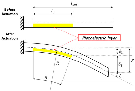
Figure 1.
Side-view schematic of the deflection of a piezo-composite unimorph actuator.
To calculate the load-carrying and deflection characteristics of piezo-composite beams, we adopted the Euler–Bernoulli beam theory, which is a simple linear theory for elasticity assuming that beam cross sections are symmetrical about a plane perpendicular to the neutral plane without any slippage between layers under a bending moment.
Based on the Euler–Bernoulli beam theory, a simple analytical model for describing the curvature change of a layered unimorph actuator (see Figure 2) can be expressed using Equations (4)–(6).
where a is the length of the moment arm from the neutral axis of the neutral surface of the beam; D is the total bending stiffness, which is the sum of the bending stiffness of each layer with respect to the neutral axis; Ei and Ii are the modulus and area moment of inertia of each layer, respectively; Ea, , ta, and wa are the elastic modulus, cross-sectional area, thickness, and width of the actuation layer, respectively; d3x is the piezoelectric strain constant in the x-axis direction with an electric field on a third axis in the thickness direction; and is the vatiation of excitation voltage. We define the coefficient of a piezoelectric unimorph actuator cpua in Equation (7) as the ratio of a to D, multiplied by Ea, d3x, and .
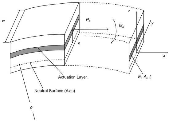
Figure 2.
Schematic of the curvature change in a laminated beam with an electro active layer [6]. (Copyright from IOP Science 2004).
Based on Equations (7) and (8), it is expected that if the cross section of a layered unimorph actuator is designed to have a higher value of cpua, a greater curvature change should be observed.
2.2. Lay-Up Structure Design of a Unimorph Cantilever
Based on the LIPCA design principle defined in Equations (7) and (8), it is clear that the greater the coefficient of a piezoelectric unimorph actuator, the greater the curvature change that can be generated. The LIPCA-S2 [12], which uses a PMN-29PT single-crystal layer, and the LIPCA-C3 [8], which uses a poly-crystal piezoelectric ceramic layer, were analyzed to compare the actuation performances of piezo-composite unimorph cantilevers. These actuators were designed, manufactured, and tested in our Artificial Muscle Research Laboratory. The lay-up structures of the LIPCA-S2 and the LIPCA-C3 are presented in Figure 3 and Figure 4, respectively. The cpua value of each lay-up structure was calculated by applying the material properties listed in Table 1.
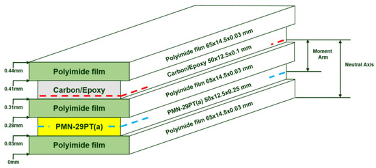
Figure 3.
Lay-up structure of the lightweight piezo-composite unimorph actuator (LIPCA-S2) [12]. (Copyright from Taylors & Francis Online, http://www.tandfonline.com).
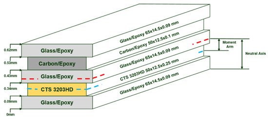
Figure 4.
Lay-up structure of LIPCA-C3 [8].

Table 1.
Properties of materials used in LIPCA-S2 and LIPCA-C3.
2.3. Fabrication of Piezo-Composite Actuators
The layers of the LIPCA-S2 were stacked on a flat mold using the stacking sequence depicted in Figure 3. A bottom layer of polyimide film (65 mm × 12.5 mm × 0.03 mm) with a coated high-temperature adhesive film and printed copper electrode circuit was placed on a flat base mold, and a PMN-29PT(a) piezoelectric layer (50 mm × 12.5 mm × 0.25 mm) was laid on top of the bottom layer. Another electric insulating polyimide film layer with a coated high-temperature adhesive film and printed copper electrode circuit on the bottom surface was placed on top of the piezoelectric layer. A carbon/epoxy unidirectional prepreg (50 mm × 12.5 mm × 0.1 mm) and a top polyimide film layer were then stacked on top. The stacked laminate was vacuum-bagged and cured in an oven at an elevated temperature (177 °C) following the prepreg curing cycle. The cured LIPCA-S2 and LIPCA-C3 were connected to an electric power line via soldering, as shown in Figure 5.
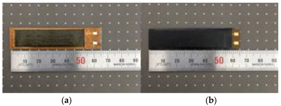
Figure 5.
Manufactured LIPCA-S2 and LIPCA-C3. (a) LIPCA-S2 (b) LIPCA-C3.
3. Characterization of the Orthotropic Properties of a PMN-29PT Single Crystal
PMN-29PT single-crystal materials are piezoelectric materials with orthotropic piezoelectric strain coefficients and an orthotropic elastic modulus that can change when stresses vary. Because variations in piezoelectric strain coefficients and the elastic modulus may affect the actuation performance of a piezo-composite actuator, we performed characterizations of these properties based on stress variation. To characterize the orthotropic properties, 0° (one-axis direction of a piezoelectric layer plane) and 90° (two-axis direction of a piezoelectric layer plane) coupon specimens with dimensions of 12.5 mm × 25.0 mm × 0.5 mm were cut from a PMN-29PT wafer. Thin gold electrodes were deposited on the upper and lower surfaces and the electrode wires were connected via soldering. Strain gauges were bonded to the electrode surfaces in the longitudinal and transverse directions, as shown in Figure 6.

Figure 6.
Schematic of compression testing for the characterization of thin piezoelectric layers.
Supporting plates were placed on both surfaces to prevent bending deformation of the specimens during the in-plane compression loading process. The specimens and supporting plates were placed into the compression jigs of a compression loading test machine. The compression stress measured by a load cell was controlled by adjusting a rotating wheel that moved the middle plate of the compression test machine, as shown in Figure 7. Using strain measuring equipment, strains were recorded by increasing the excitation voltage up to 450 V for different compression stresses of 0, 3.1, 5.5, 7.8, 11.8, and 15.7 MPa.
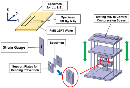
Figure 7.
Compression testing equipment system for thin piezoelectric layers.
Figure 8 presents the measured strain data for each compression stress condition. All the tests were performed three times on each specimen. One can see that the variation in compression strain generated by electric field excitation decreases significantly when the compression stress increases. Figure 9 reveals that the d32 value in the measured strain data decreases by approximately 80% when the piezoelectric single-crystal layer is compressed by 15.7 MPa of pressure in the two-axis direction, but d31 does not change significantly. It is noteworthy that d32 changes significantly at approximately 12 MPa, which can be explained by a phase transition from a tetragonal phase to a rhombohedral phase. The elastic modulus E2 values obtained from the measured data of compression stress and strain are presented in Figure 10 with no electric field. One can see that E2 decreases by approximately 40% near the phase transition compression stress level, but E1 does not change significantly. By comparing d31 and d32 in Figure 9 and E1 and E2 in Figure 10, we found that there is a significantly different orthotropy between d31 and d32, and a very similar orthotropy between E1 and E2. This orthotropy of a PMN-29PT single-crystal layer may facilitate the design of a unimorph actuator to increase actuation performance. A similar behavior was reported by Feng et al. [16], who found that moderate uniaxial stress can improve electromechanical properties, but high stress results in crystal depolarization and suppressed electromechanical responses, severely limiting actuator materials. They also explained that nonlinear behavior and hysteresis are the result of polarization switching and ferroelastic domain switching, which can be analyzed using the X-ray diffraction analysis.
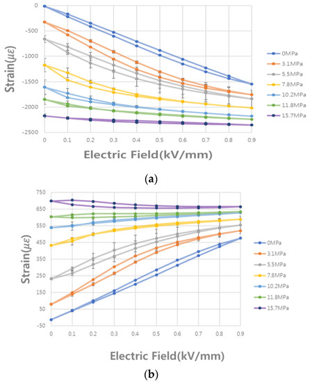
Figure 8.
Measured strain vs. electric field variation for different compression stresses in both axis directions. (a) Measured strain in the two-axis direction [14]; (b) Measured strain in the one-axis direction.
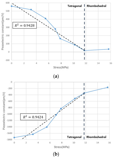
Figure 9.
d32 and d31 values calculated from the measured strain data for compression stress variation. (a) Piezoelectric strain coefficient d32; (b) Piezoelectric strain coefficient d31.
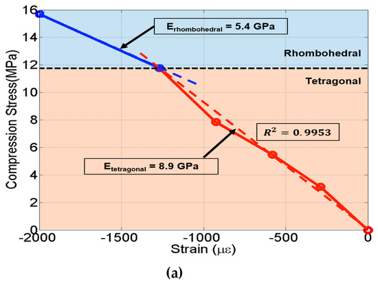
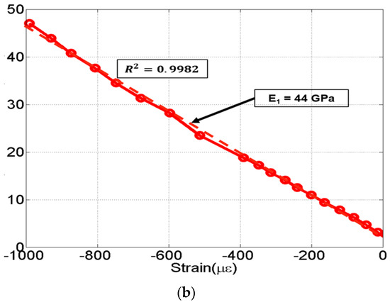
Figure 10.
Elastic moduli calculated from compression testing data. (a) Measured modulus E2 obtained from two-axis direction compression loading; (b) Measured modulus E1 obtained from one-axis direction compression loading.
4. Internal Residual Stress Analysis of a Laminate
In an orthotropic material layer, the strains induced by piezoelectric deformation are also orthotropic. We denote the piezoelectric strain coefficients (strain/V) as d31 and d32, in the material principal axis direction. The change of piezoelectric strains induced by a change in electric field excitation voltage divided by thickness of piezoelectric layer) are defined as
where d31 and d32 are the piezoelectric strain coefficients for strain induced in the one-axis and two-axis directions, respectively, with an applied electric field in the three-axis (thickness) direction.
The stress–strain relationship equation for a laminate [6] was modified to generate Equation (10) to include piezoelectric deformation effects and calculate internal stresses induced by piezoelectric actuation itself, as well as any temperature variation during the specimen curing process.
where is the stress vector, is the strain vector, is the coefficient of thermal expansion vector, and is the temperature change during the curing process. Here, the x direction is the axis direction perpendicular to the actuator beam cross section and the y direction is the axis direction parallel to the actuator beam cross section. Figure 11 and Figure 12 present the calculated internal stresses in the principal geometrical direction of the plane section perpendicular to the principal axes of LIPCA-S2 and LIPCA-S3, respectively. One can see that the internal compression stress of the piezoelectric material layer increases when we increase the excitation electric field for both LIPCA-S2 and LIPCA-C3. Therefore, it is expected that the piezoelectric strain coefficient and elastic modulus will decrease when the excitation electric field increases based on the data in Figure 9 and Figure 10.
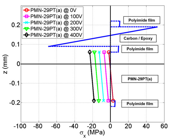
Figure 11.
Internal stresses in a LIPCA-S2 laminate section. (Solid line: stress value of each layer. Dashed line: boundary between layers).
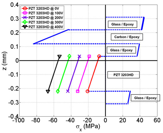
Figure 12.
Internal stresses of a LIPCA-C3 laminate section. (Solid line: stress value of each layer. Dashed line: boundary between layers).
5. Performance Evaluation of Actuators and Discussion
A device for measuring the tip displacement of a unimorph cantilever was constructed to characterize the performance of LIPCA-S2 and LIPCA-C3. As shown in Figure 13, the measuring system consisted of a jig to fix the cantilever actuator, a high-voltage actuation signal generator (TD-2 power supply, Face International Corporation, Norfolk, USA, and a non-contact laser displacement measuring system (Keyence LK-081, RJ-800), which is the same measuring system used in [12]. Figure 14 presents the measured deflection and predicted deflection of the LIPCA-S2 and the LIPCA-C3 up to an applied static electric field of 450 V. One can see that the actuation displacements of the LIPCA-S2 at 450 V are 264% greater than those of the LIPCA-C3. The cpua values of the LIPCA-S2 and the LIPCA-C3 are compared in Table 2. One can see that the cpua values of the LIPCA-S2 are 780% greater than those of the LIPCA-C3, indicating that greater actuation displacement can be obtained from an actuator with a greater cpua value.
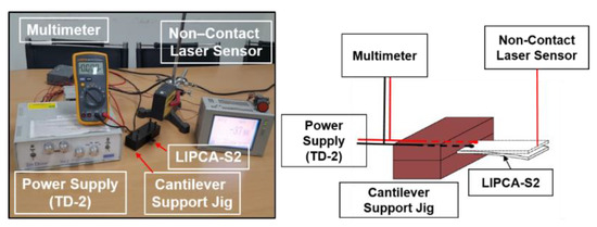
Figure 13.
Equipment for measuring the tip displacement of a unimorph cantilever.
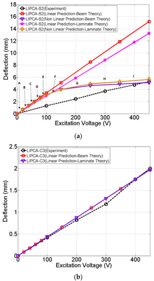
Figure 14.
Actuation displacements of the LIPCA-S2 and the LIPCA-C3. (a) Actuation displacement of the LIPCA-S2; (b) Actuation displacement of the LIPCA-C3.
Table 2.
Comparison of actuator performances and characteristics.
The measured and predicted actuation displacements are compared in Figure 14a for the LIPCA-S2 and Figure 14b for the LIPCA-C3. It was found that the measured actuation displacement of the LIPCA-C3 can be accurately predicted using the linear mathematical prediction model defined in Equation (8). However, the predicted actuation displacement of the LIPCA-S2 cantilever tip using the linear prediction model was more than three times greater than the measured data. To reduce this large discrepancy between the predicted and measured data, variations in material properties with changes in the compression stress of a PMN-29PT piezoelectric single crystal were considered using the nonlinear prediction method. The core idea of the nonlinear prediction method is to use different d32 and E2 values, which are obtained from measured strains, for different compression stresses at each level of excitation voltage, as shown in Table 3. These values were derived from measured data in Figure 9 and Figure 10. For a specific level of voltage, the internal compression stress level can be calculated using Equation (10) and the corresponding d32, d31, and E2 values can be obtained from Figure 9 and Figure 10. The corresponding curvature change and tip displacement can be predicted for each electric field increment. The predicted total tip displacement of the nonlinear prediction model is equal to the sum of each individual tip displacement. We found that the actuation displacement of the LIPCA-S2 cantilever can be predicted more accurately by using the nonlinear prediction model with varied piezoelectric strain coefficients d32 and d31, and elastic moduli E2, even though there is still a considerable difference between the predicted and measured values. To reduce the prediction discrepancies at lower voltages, additional theories, such as the classical laminate plate theory that considers the change in the elastic modulus E2, d32, and d31 to determine the variation in the two-dimensional plane stresses (σxx, σyy, σxy), effects of longitudinal-transverse and regular interactions of the layers, and voltage actuation at the boundaries of a piezoelectric layer, will be considered in subsequent studies.
Table 3.
Changes in PMN-29PT material properties with compression stress variations.
6. Conclusions
The LIPCA-S2 and the LIPCA-C3, which are piezo-composite unimorph actuators with piezoelectric layers, were tested and analyzed to predict tip displacement performance during the actuation process based on electric excitation. The measured actuation displacement of the LIPCA-C3 was accurately predicted using the proposed linear prediction model. However, we found that the predicted displacement of the LIPCA-S2 cantilever tip was more than three times the measured displacement when using the linear prediction model. To reduce this large discrepancy between the predicted and measured results, the nonlinear material behaviors of a PMN-29PT piezoelectric single crystal were considered. Based on piezoelectric deformation tests under various compression stresses, we found that the piezoelectric strain coefficient obtained from the measured strain data was reduced by approximately 80% when a piezoelectric single-crystal layer was compressed by 15.68 MPa of pressure in the two-axis direction. Additionally, the elastic modulus E2 decreased by more than 40% while the elastic modulus E1 remained relatively stable. It was also found that the actuation displacement of a LIPCA-S2 cantilever can be predicted more accurately by using a nonlinear prediction model instead of a linear prediction model.
Author Contributions
Experimental verification and writing, J.H.L.; conceptualization, B.S.Y.; formal analysis, J.-W.P.; data curation G.S.; and supervision, K.J.Y. All authors have read and agreed to the published version of the manuscript.
Funding
This work was supported by the Korea Institute of Energy Technology Evaluation and Planning (KETEP) and the Ministry of Trade, Industry & Energy (MOTIE) of the Republic of Korea (No. 20183010014230).
Conflicts of Interest
The authors declare no conflict of interest.
References
- Haertling, G.H. Rainbow Actuators and Sensors: A New Smart Technology. In Proceedings of the International Society for Optical Engineering, San Diego, CA, USA, 3–4 March 1997; Simmons, W.C., Aksay, I.A., Huston, D.R., Eds.; SPIE: Bellingham, WA, USA, 1997; Volume 3040, pp. 81–92. [Google Scholar]
- Barrett, R.; Gross, R.S.; Brozoski, F. Missile flight control using active flexspar actuators. Smart Mater. Struct. 1995, 2443, 121–128. [Google Scholar] [CrossRef]
- Barrett, R.; Gross, R.S.; Brozoski, F. Design and Testing of a Subsonic All-Moving Adaptive Flight Control Surface. Am. Inst. Aeronaut. Astronaut. 1997, 35, 1217–1219. [Google Scholar] [CrossRef]
- Hellbaum, R.; Bryant, R.G.; Fox, R. Thin Layer Composite Unimorph Ferroelectric Driver and Sensor. U.S. Patent US 5,632,841, 27 May 1997. [Google Scholar]
- Mossi, K.; Bishop, R.P. Characterization of Different types of High Performance THUNDER Actuators. In Proceedings of the International Society for Optical Engineering, Newport Beach, CA, USA, 12 July 1999; Wuttig, M.R., Ed.; SPIE: Bellingham, WA, USA, 1999; Volume 3675. [Google Scholar]
- Yoon, K.J.; Park, K.H.; Lee, S.K.; Goo, N.S. Analytical design model for a piezo-composite unimorph actuator and its verification using lightweight piezo-composite curved actuators. Smart Mater. Struct. 2004, 13, 459–467. [Google Scholar] [CrossRef]
- Nguyen, N.T.; Yoon, B.S.; Park, K.H. Analyticlal model and optimal design of a d33-mode active layer for the lightweight unimorph piezo-composite actuator. J. Electroceramics 2011, 26, 175–184. [Google Scholar] [CrossRef]
- Nguyen, N.T.; Yoon, K.J.; Park, H.C. Actuation displacement of unimorph piezoelectric actuators with external loading. J. Korean Phys. Soc. 2007, 51, 11–15. [Google Scholar] [CrossRef]
- Bryant, R.G. Overview of NASA Langley’s Piezoelectric Ceramic Packaging Technology and Applications. In Proceedings of the 10th Japan International SAMPE Symposium and Exhibition, Tokyo, Japan, 27–30 November 2007. [Google Scholar]
- Kang, L.H.; Lee, J.W.; Han, J.H. Development of a piezoelectric unimorph using a mechanically pre-stressed substrate. Smart Mater. Struct. 2009, 18, 1–9. [Google Scholar] [CrossRef]
- Kang, L.H.; Han, J.H. Prediction of actuation displacement and the force of a pre-stressed piezoelectric unimorph (PUMPS) considering nonlinear piezoelectric coefficient and elastic modulus. Smart Mater. Struct. 2010, 19, 1–11. [Google Scholar] [CrossRef]
- Park, J.H.; Yoon, B.S.; Yoon, K.J. Experimental investigation on the piezo-composite actuator with piezoelectric single crystal layer. Adv. Compos. Mater. 2016, 25, 487–496. [Google Scholar] [CrossRef]
- Yoon, B.S.; Park, J.H.; Yoon, K.J. Experimental study on control fins of a small flying vehicle using piezo-composite actuators. Adv. Compos. Mater. 2017, 26, 35–43. [Google Scholar] [CrossRef]
- Yoon, B.S.; Park, J.W.; Yoon, K.J.; Choi, H.Y. Deflection Prediction of Piezo-composite Unimorph Actuator Considering Material Property Change of Piezoelectric Single Crystal for Compression Stress Variation. Compos. Res. 2017, 30, 15–20. [Google Scholar] [CrossRef][Green Version]
- Nguyen, X.H.; Mau, T.H.; Meyer, I.; Dang, B.; Pham, H. Improvements of Piezo-Actuated Stick–Slip Micro-Drives: Modeling and Driving Waveform. Coatings 2018, 8, 62. [Google Scholar] [CrossRef]
- Feng, Z.; Lin, D.; Luo, H.; Li, S.; Feng, D. Effect of uniaxial stress on the electromechanical response of.001.-oriented Pb.Mg1/3Nb2/3.O3–PbTiO3 crystals. J. Appl. Phys. 2005, 97, 1–5. [Google Scholar] [CrossRef]


© 2020 by the authors. Licensee MDPI, Basel, Switzerland. This article is an open access article distributed under the terms and conditions of the Creative Commons Attribution (CC BY) license (http://creativecommons.org/licenses/by/4.0/).