Article

Microstructures and Wear Resistance of FeCoCrNi-Mo High Entropy Alloy/Diamond Composite Coatings by High Speed Laser Cladding

1
Powder Metallurgy Research Institute, Central South University, Changsha 410083, China
2
College of Engineering, Nanjing Agricultural University, Nanjing 210031, China
*
Authors to whom correspondence should be addressed.
Coatings 2020, 10(3), 300; https://doi.org/10.3390/coatings10030300
Submission received: 14 February 2020 / Revised: 19 March 2020 / Accepted: 20 March 2020 / Published: 24 March 2020
(This article belongs to the Special Issue Surface Treatment by Laser-Assisted Techniques)

Abstract

:
FeCoCrNi-Mo high entropy alloy/diamond composite coatings were successfully prepared by high speed laser cladding. A high scanning speed was adopted (>30 mm/s), and the effects of laser power, scanning speed, and diamond content on the microstructure and wear resistance of the composite coating were studied. The processing parameters of laser cladding had significant influence on the dilution ratio, graphitization of diamond, and wear resistance of the composite coatings. When the laser cladding parameters were 3000 W of laser power and the high scanning speed of 50 mm/s, the composite coating exhibited a uniform microstructure, the lowest dilution ratio, and the best wear resistance. The wear resistance of the composite coating was enhanced with the addition of diamond, but microcracks also increased. When the amount of diamond was 15 wt.%, the best combination of microstructures and wear resistance was obtained.

1. Introduction

A diamond rope saw is a cutting tool with high hardness and flexibility, and which is widely used in stone cutting in mining and other industries [1,2,3,4]. Diamond string beads are the functional component in the diamond rope saw. Preparation methods of diamond string beads are mainly electroplating [5], sintering [6], and brazing methods [7]. The electroplating method is where the diamond is placed on the metal substrate to form a working layer, which is simple in technology but poor in wear resistance. The sintering method is to mix diamond and the matrix powders for granulating, and then combine them with the metal matrix for sintering. This method obtains good wear resistance and a long service life, but the process is complex, and the cost is high. For the brazing method, a layer of carbide is formed on the surface of the diamond by brazing filler metal containing strong carbide forming elements (Ti, Cr, W, etc.) to realize the chemical combination of diamond and matrix, so as to improve the wear resistance. However, in the brazing process, the retention of the matrix on the diamond abrasive particles is insignificant, and the abrasive particles easily fall off.
With the rapid development of laser technology in recent years, the laser cladding method has the advantages of preparing composite component materials with enhanced mechanical properties and fine and homogeneous microstructures [4]. In processing factors, laser cladding benefits from having unique features such as low heat affected zone, high cooling rate, and low dilution [8,9]. Laser cladding provides a novel idea for the preparation of diamond/metal matrix composite and its coating to avoid the shortcomings of the traditional method and achieve a high-performance workpiece [10,11,12,13]. Rommel [11], Iravani [12], and Mehrdad [14] used laser cladding technology to prepare diamond/metal matrix composite coatings. The interface bonding behavior between the diamond and metal matrix and the effect of laser cladding process parameters on microstructures and mechanical properties were studied. These results show that under the influence of different laser cladding process parameters, there are great differences in the thermal damage and graphitization of diamond particles, the bonding behavior between diamond and metal matrix, porosity and microcracks, and the dilution effect.
The combination of laser cladding technology and high entropy alloys is a new attempt in coating technology, and also a new method for the development of high entropy alloys (HEAs). HEAs have excellent high temperature stability, wear resistance, and corrosion resistance, so they exhibit great application potential in coating technology [15,16,17]. The rapid heating and cooling rate of laser cladding can refine the microstructures of the coating, and the combination of the two aspects can achieve the complementary effect and further increase the mechanical properties of the coating.
Moreover, the thermal stability of diamond is poor. In the laser cladding process of diamond–HEA composite coating, due to the concentration of laser energy, if the laser contacts the diamond for a long time, the tendency for diamond graphitization is intensified, and the HEA matrix and diamond can diffuse with each other to form carbides. Usually, for the metallic and alloy coating, the laser scanning speed is usually reduced (<20–30 mm/s) to obtain a coating with high bonding strength with the substrate. However, the thermal damage of diamond is irreversible.
Thus, high speed laser cladding was adopted in this study, which can not only make the coating have a good combination with the substrate, but also inhibits the graphitization of diamond and the carbonization reaction of metal components in HEA with diamond. Therefore, it is necessary to systematically study the microstructures and mechanical properties of the diamond composite coating by high speed laser cladding. In this study, FeCoCrNi-Mo HEA/diamond composite coatings were prepared by high speed laser cladding technology. The effects of processing parameters, such as laser power and scanning speed, and diamond addition on the microstructure, hardness, and wear resistance of the composite coatings was systematically discussed.

2. Experimental

Standard MBD4-type synthetic diamond (140–170 mesh average) was provided by Huanghe Whirlwind Co., Ltd. (Xuchang, China). Diamond was deposited in the magnetron sputtering coating equipment with argon atmosphere to form a Ti–Ni protective layer. Ti and Ni (inner Ti and outer Ni) with purity higher than 99.99% were used as targets. The layer was deposited about 15 µm thick. Fe24.1Co24.1Cr24.1Ni24.1Mo3.6 (at.%) HEA powders prepared by gas atomization were applied as matrix materials, in which the average particle size was about 50 µm. The coated diamonds were mixed with HEA powders uniformly in the mixer for 5 h (mixer speed: 60 r/min); the coated diamond contents were 5 wt.%, 10 wt.%, 15 wt.%, and 20 wt.%, respectively.
FeCoCrNi-Mo HEA/diamond composite coatings were prepared on 42CrMo steel substrate by using laser cladding equipment with a laser line fiber-coupled semiconductor laser (Fraunhofer, Aachen, Germany), ABB manipulator (ABB, Zurich, Switzerland), and coaxial powder delivery. The laser powers were 3000, 4000, 5000, and 5500 W, and the scanning speeds were 30, 40, 50, and 60 mm/s, respectively. The laser spot diameter was 4.6 mm. The protective gas was argon with a 20 L/min flow rate. The surface of 42CrMo steel was polished, ultrasonic cleaned, and dried.
The hardness of the alloy was determined by using a Vickers hardness tester (BUEHLER5104, Buehler, Lake Bluff, American) under a 200 g load for 15 s and was averaged from three measurements. The wear properties were measured by HRS-2M high-speed reciprocating friction test equipment (HRS-2M, Zhongke Kaihua, Lanzhou, China) with a friction time of 15 min, 50 N loading, 15 Hz frequency (900 times/min), and a 5 mm stroke. A scanning electron microscope (SEM, FEI, Quanta 250 FEG, Vlastimila Pecha, Czech Republic) equipped with an energy dispersive spectrometer (EDS) was used to investigate the microstructure and chemical compositions of the samples.

3. Results and Discussions

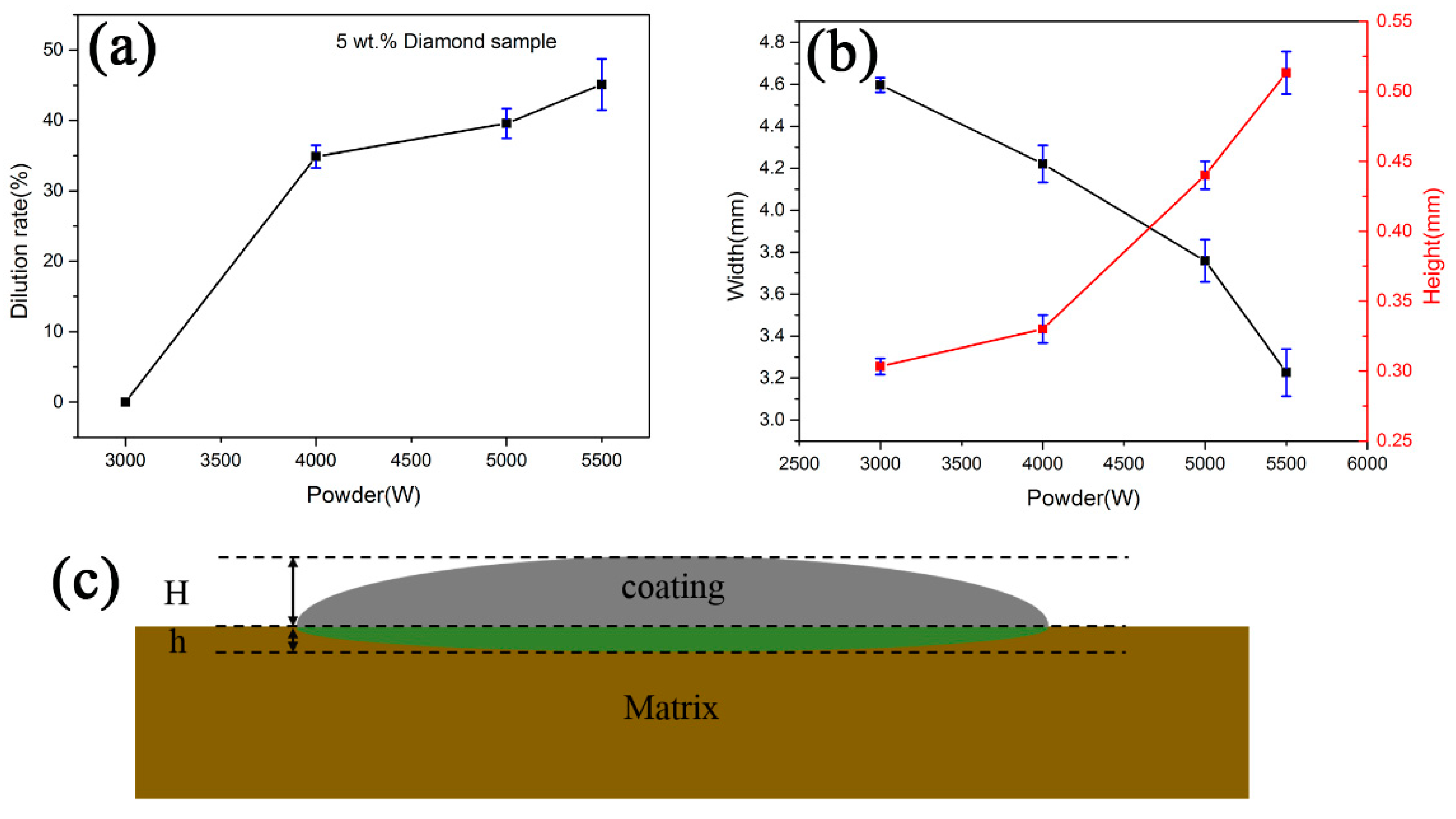
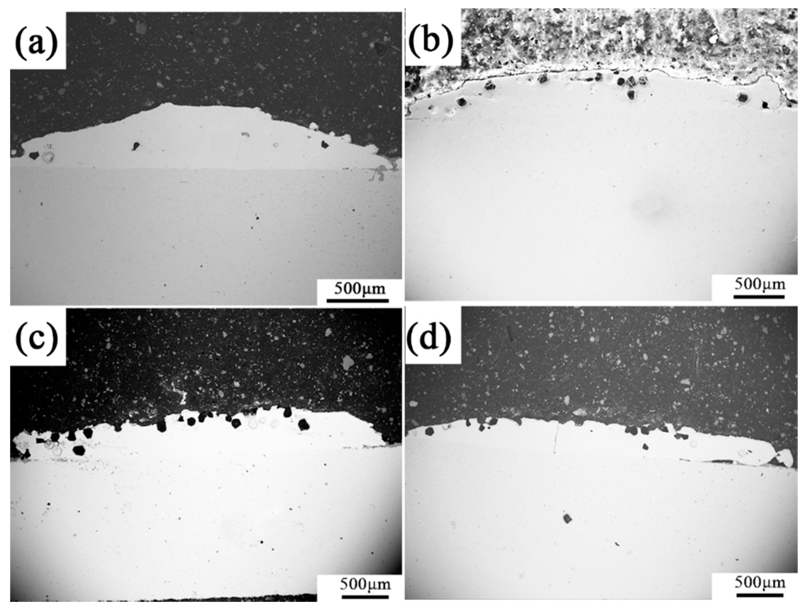
3.1. Effect of Laser Power

3.1.1. Microstructures

Figure 1a shows the macro-morphology of the FeCoCrNi-Mo/diamond composite coating (diamond content 5 wt.%) prepared with different laser powers at high scanning speed of 50 mm/s. With the increase of laser power, the color of the coating surfaces changed from pale yellow to black. This shows that with the increase of laser power and the temperature of the molten pool, the laser energy density of the diamond particles increased, which led to the graphitization of the diamond particles. The C element of decomposed diamond reacted with the strong carbide forming elements in the HEA matrix, such as Cr, to form a large number of carbides. The typical microstructure of the coating by laser cladding is shown in Figure 1b. The coating can be divided into four areas, namely cladding layer, bonding area between substrate and coating, heat affected area, and substrate.
Figure 2 shows the longitudinal sectional morphology with a cross section inside of the coating under different laser powers. It can be seen that with the increase of laser power, the diamond content obviously decreased, and a lot of porosity appeared in the coating. When the power was 5500 W, obvious microcracks were found in the coating. The reason is that with the increase of laser power, the graphitization of diamond increased, and diamond particles began to decompose, which caused the declination of the diamond content. More free C atoms diffused into the HEA matrix, inevitably reacted with the oxygen introduced from the air, and formed a gas. The rapid solidification rate of laser cladding led to the gas not being able to be discharged and remained in the coating, forming micropores. On the other hand, the intensified diffusion of a C element resulted in the formation of a large number of carbides in the coating, which increased the residual stress in the coating and caused microcracks.
The dilution ratio of the composite coating prepared by different laser powers is shown in Figure 3a. The schematic diagram of coating and the calculation of dilution ratio η are shown in the Figure 3c and Formula (1), respectively. In Formula (1), h is the coating height and H is the depth of the bonding area.
η = h h + H
The dilution ratio of coating refers to the change of coating composition caused by the diffusion of substrate elements into the coating due to the melting of the substrate during laser cladding. When the dilution ratio is too low, the bonding force between the substrate and the coating is reduced, and metallurgical bonding cannot be formed, and even the coating will fall off. When the dilution ratio is too high, the matrix will over-dilute the coating, which will increase the uncertainty of the coating composition, increase the tendency of cracking and deformation, and reduce the coating performance, as shown in Figure 3a, with the selected scanning speed of 50 mm/s, and the dilution rate of the coating increased with the increase of laser power. When the laser power was 3000 W, the dilution ratio of the coating was almost zero; when the laser power was increased to 4000 W, the dilution ratio of the coating increased sharply to 35%; when the laser power was further increased, the variation of the dilution ratio became gentle gradually, and finally reached 47% at 5500 W.
When the laser power was low, the temperature of the molten pool was relatively low, so the heat affecting the substrate was weak with a low dilution rate. On the other hand, when the laser power was high, the laser energy could melt the powders and effected the substrate, improving the metallurgical bonding. However, at the same time, too many elements of the substrate were introduced into the coating, which had an impact on the performance of the coating.
During laser cladding, there is splashing or ablation of powder under the laser condition. As a result, not all powders are utilized. In order to calculate the utilization ratio of powder, according to [18], the formula for the utilization ratio of powder is as follows:
λ = ρ B H V s V f
In Formula (2), λ is the powder utilization rate (%), B and H are width and average height of the coatings (mm), respectively, Vs is scanning speed (mm/s), Vf is the powder delivery rate (g/s), and ρ is powder density (g/cm3). The relationship between laser power and coating size is shown in Figure 3b when the scanning speed Vs and the powder feeding rate Vf were constant. According to Formula (1), when the laser power was 3000 W, the powder utilization rate was the largest, and it decreased slightly with the increase of laser power. This is because the increase of laser power made the thermal effect on the substrate, becoming stronger gradually, and the increase of the dilution ratio led to the decrease of the size of the coating.

3.1.2. Mechanical Properties

Figure 4a shows the microhardness of composite coatings with laser power. The trend of microhardness change with laser power was to increase first and then decrease. When the laser power was 3000 W, the average hardness of the coating was 329 HV0.2; when the laser power was 5000 W, the maximum average microhardness of the coating reached about 404 HV0.2. However, when the laser power continued to increase to 5500 W, the microhardness decreased to 333.28 HV0.2. The reason is that at high laser power, the higher dilution ratio led to serious diffusion of substrate into the coating, resulting in the inhomogeneous composition and microcracks in the coating. These microcracks reduced the continuity of the coating and released the internal stress of the coating, resulting in the obvious reduction of the microhardness.
A friction test is the method to reflect the grinding or wear resistance of materials. The friction coefficient tends to be gentle and stable when the materials have good and stable wear resistance. Figure 4b shows the friction coefficient–time curves of the composite coatings prepared by different laser powers. When the scanning speed was 50 mm/s, with the increase of laser power, the friction coefficient of the coating decreased first and then increased. When the laser powers were 3000 W and 5500 W, the friction coefficient of the coatings was about 0.5, which was higher than the intermediate laser power of about 0.3. Therefore, the wear resistance of coatings were further determined by the worn surface of the counterpart Si3N4 ball. Figure 5 shows the worn surface of Si3N4 dual ball against the coatings prepared with different laser powers. Figure 5a–h corresponds to the laser power at 5500, 5000, 4000, and 3000 W, respectively, and the worn area of the corresponding Si3N4 ball was 3.08, 3.38, 3.14, and 12.82 mm2, respectively. It can be seen from Figure 5a,b that the worn area of high power (5500 W) to the Si3N4 ball was the smallest, and the worn surface was relatively flat with few ploughings. With the decrease of laser power, the worn area increased, and the ploughing of the worn surface of Si3N4 ball increased, as shown in Figure 5c–f. At the lowest laser power (3000 W), the area of wear mark and the number of ploughing increased sharply, the wear mechanism changed from adhesive wear to abrasive wear, and the wear resistance of coating was the best, as shown in Figure 5g,h.
The reason why the wear resistance of the coatings was worse with the increase of power is that the wear resistance of HEA/diamond composite coatings lies in the cutting effect of diamond particles retained by the HEA matrix. Therefore, whether the high hardness and wear resistance of diamond can be maintained after laser cladding is the key factor to determine the performance of coatings. However, the thermal stability of diamond is relatively poor. If the heating temperature of diamond is higher than 840–940 °C in air or 950–1100 °C in a vacuum, oxidation and graphitization occur [18]. In addition, a diamond is easy to react with some transition metal elements (most of them are strong carbide forming elements) to form carbides in the process of coating preparation, which also cause diamond failure.
Considering the microstructure and mechanical properties of FeCoCrNi-Mo/diamond composite coatings prepared by different laser powers, when the laser power was 3000 W, the coating was relatively optimal. Thus, the scanning speed is changed under the condition of 3000 W to explore the influence of scanning speed on the microstructures and properties of the composite coating.

3.2. Effect of Scanning Speed

3.2.1. Microstructures

The scanning speed also has an important influence on the microstructure and performance of the composite coating. Low scanning speed causes serious ablation of the powders; high scanning speed increases the amount of un-melted powders in the coating, resulting in poor bonding between the coating and the substrate. Therefore, FeCoCrNi-Mo/diamond composite coatings with the same 5 wt.% diamond addition were prepared by using the scanning speed of 30, 40, 50, and 60 mm/s with the specific laser power of 3000 W. It should be noted that the speed range of 30–60 mm/s is higher than normal laser cladding for metallic materials or alloys. The morphology of the coatings is shown in Figure 6.
It can be seen from Figure 6a that there were a lot of un-melted HEA powder particles on the coating surface due to the high scanning speed; un-melted powders can lead to poor bonding between the coating and substrate and result in micro-cracks. With the decrease of scanning speed, the width of the coating decreased, but the dilution ratio of the coating increased, as shown in Table 1. This is because the low scanning speed enhanced the interaction time between laser and powder/substrate, resulting in a larger heat affected zone of the coating; thus, the dilution ratio of the coating increased, accompanied with the declination of diamond content, as shown in Figure 6b,c. As the scanning speed further decreased to 30 mm/s, it can be seen from Figure 6d that the absorption rate of the coating for laser energy reached the highest, the dilution rate was the largest, and there was a lot of ablation of HEA powders. Moreover, long-term contraction between diamond particles and the laser at such a low scanning rate would inevitably lead to serious oxidation and graphitization of the diamond and loss by its own wear-resistant characteristics.

3.2.2. Mechanical Properties

Due to the deterioration of coating properties caused by higher or lower scanning speed, the mechanical properties of coatings prepared by moderate scanning rate were investigated, such as 40 and 50 mm/s. When the scanning speed was 40 and 50 mm/s, the average micro-hardness of the coating was 329 HV0.2 and 312 HV0.2, respectively. The micro-hardness of the two coatings was close to each other, so the trends of friction coefficient–time curve and friction coefficient were similar. As shown in Figure 7a, when the scanning speed was 50 mm/s, the initial friction coefficient of the coating was higher than the 40 mm/s sample, and the curves turned to be stable quickly, slightly higher than the 40 mm/s sample, with the average friction coefficient of 0.41 and 0.37, respectively. Figure 7b,c shows the worn surface of the Si3N4 dual ball against the coatings prepared by the scanning speed of 40 and 50 mm/s, respectively. Compared with the sample by 50 mm/s (12.82 mm2), the worn area of the dual ball was significantly reduced in the 40 mm/s sample to only 3.98 mm2. It exhibited a mixed wear mechanism of adhesive wear and abrasive wear. When the scanning speed was reduced from 50 to 40 mm/s, due to the increasing contact time between diamond particles and laser, the graphitization of diamond became more serious, and the wear-resistance of the coating was significantly reduced.

3.3. Morphology of Diamond

The existence of the diamond in the composite coating has a significant effect on the retention of a matrix of diamond, and the grinding effect of the coating. It is expected that the graphitization of diamond and serious diffusion between diamond and HEA are restrained while the metallurgical bonding of diamond with HEA matrix is realized. Table 2 shows the grinding effect of composite coatings with different laser power and scanning speed, which is inextricably related to the morphology of diamond in the coating.
During the laser cladding process, when the laser power was 3000 W and scanning speed was 50 mm/s, HEA powder completely melted and formed good bonding with diamond particles in the FeCoCrNi-Mo/diamond composite coating, as shown in Figure 8a. Meanwhile, there was strong metallurgical bonding between the HEA matrix and diamond through the diffusion of Cr, which played an important role in improving the retention of matrix to diamond. Only a small amount of C in the diamond changed into free C atoms, which formed metallurgical bonding with HEA matrix and partially diffused into the HEA matrix to realize the interstitial solution strengthening of the matrix and further improved the retention. These results were confirmed in our previous study [19]. On the other hand, the dilution ratio of the coating was relatively low; only a small number of elements of steel substrate diffused into the coating and the effect on the diamond was small under the condition of very fast cooling rate in laser cladding. The diamond particle could maintain the original crystal shape and its own good mechanical properties, so it had a good grinding effect, as shown in Figure 8a and Table 2.
When the scanning speed decreased to 40 mm/s, with longer contact time between diamond and laser, under the synergistic effect of oxidation and graphitization, the diamond particle had an obvious structural transformation, gradually lost its crystal shape, the edges and corners became smooth and the size decreased, and the wear resistance decreased significantly, as shown in Figure 8b. As with the similar situation of diamond, when the laser power increased to 5500 W, as shown in Figure 8c, the diamond had obvious graphitization and completely lost its crystal shape, which meant that the diamond particle as an abrasive had failed. Although it could form a strong metallurgical bond with the HEA matrix, the diamond was seriously damaged and failed, resulting in the decrease of friction properties of the coating. In addition, when the scanning speed was too high (60 mm/s in Table 2), as shown in Figure 8d, the diamond could maintain a complete crystal shape and performance, but due to the shorter contact time between diamond and laser, there were a lot of un-melted powders in the HEA matrix, there was no metallurgical bonding with the diamond, and there were obvious gaps in the combined area of the diamond and the HEA matrix. In the process of friction, the retention of the HEA matrix of the diamond particles decreased, which would lead to the peeling off of the diamond, thus making the coating failure. Based on the morphology of the diamond and grinding effect of the coatings, the optimal processing parameters of FeCoCrNi-Mo/diamond composite coating by laser cladding were 3000 W and 50 mm/s.

3.4. Effect of Diamond Content

3.4.1. Microstructures

The diamond concentration (e.g., when the diamond volume fraction is 25%, the diamond concentration is 100%) is an important factor to determine the wear resistance of the diamond composite coating. Generally speaking, the higher the diamond concentration, the better the hardness and wear resistance of the coating. However, due to the poor compatibility between diamond and metal matrix, when the concentration is too high, the characteristics of the composite coating will be changed, resulting in poor bonding of the coating and the substrate, making the coating failure in service. Therefore, the appropriate amount of diamond was studied to improve the mechanical properties of the coating while maintaining a strong bonding strength with the substrate.
The optimal processing parameters of laser cladding were used to prepare the composite coatings with different diamond content. The diamond addition was 5 wt.%, 10 wt.%, 15 wt.%, and 20 wt.%, respectively. The cross-section microstructure of the coating with different diamond content is shown in Figure 9. The bonding of diamond and steel substrate was relatively good. The diamond particles were mainly distributed on the upper part of the coating. This is because the HEA matrix formed the molten pool during laser cladding; however, the diamond density was relatively low, and the diamond particles were suspended in the molten pool and retained these microstructures until room temperature. With the increase of the diamond addition, cracks began to appear at the edge of the coating, as shown in Figure 9c,d. As a result of the increasing diamond content, the wettability of the mixed powder and steel substrate became worse, and cracks were more likely to form in the coating.
The microstructures of the HEA matrix with different diamond content are shown in Figure 10. When the content of diamond changed from 5 wt.% to 10 wt.%, the microstructure of the coating was obviously refined. When the diamond content continued to increase to 15 wt.% and 20 wt.%, the HEA matrix in the coating exhibited dendrite growth and micro-cracks.
The C element diffused into the matrix from the diamond is a typical kind of structure-refining element, which can refine the HEA structures significantly [20]. As a heterogeneous phase, the surface of diamond particles can be used as solid–liquid interface for secondary growth of the alloy during solidification. Therefore, the microstructures of HEA were refined obviously. On the other hand, due to the solid solution of the C element entering the HEA matrix and the addition of new growth interfaces of the diamond surface, the non-equilibrium effect of solidification was intensified. Therefore, cellular growth when the content of diamond was 5 wt.% changed to dendrite growth when the content of diamond was high.
The morphology of the interface between the diamond and HEA matrix is shown in Figure 11a. There were four phases around diamond particles, namely black phase, dark gray needle-like, and massive phase, as observed in Figure 11b,c, respectively, light gray matrix phase, and white veinlet phase. EDS results are listed in Table 3. C elements from diamond particles diffused into HEA and combined with Cr elements to form Cr rich carbide phase, which was richer in Cr and C (black phase). The composition of the light gray phase was closed to the theoretical composition of a FeCoCrNi-Mo HEA matrix with interstitial solid strengthening of C element. The dark grey phase exhibited a relatively high Mo content and less Cr, referred to as the intermetallic σ phase, because the Mo element can promote FCC (Face Center Cubic) σ phase transition of the FeCoCrNi system [21], and has been proved in our previous studies using FeCoCrNi-Mo HEA with the same composition as that in this study [22,23]. The white phase had the highest Mo content and a relatively high C content, which was the Mo-rich carbide phase.
Among all alloying elements in HEA, Cr and Mo have the largest enthalpy of mixing (more negative), which is −61 and −67, respectively [24]. Compared with other elements, they are easier to form carbides, as shown in Table 4.

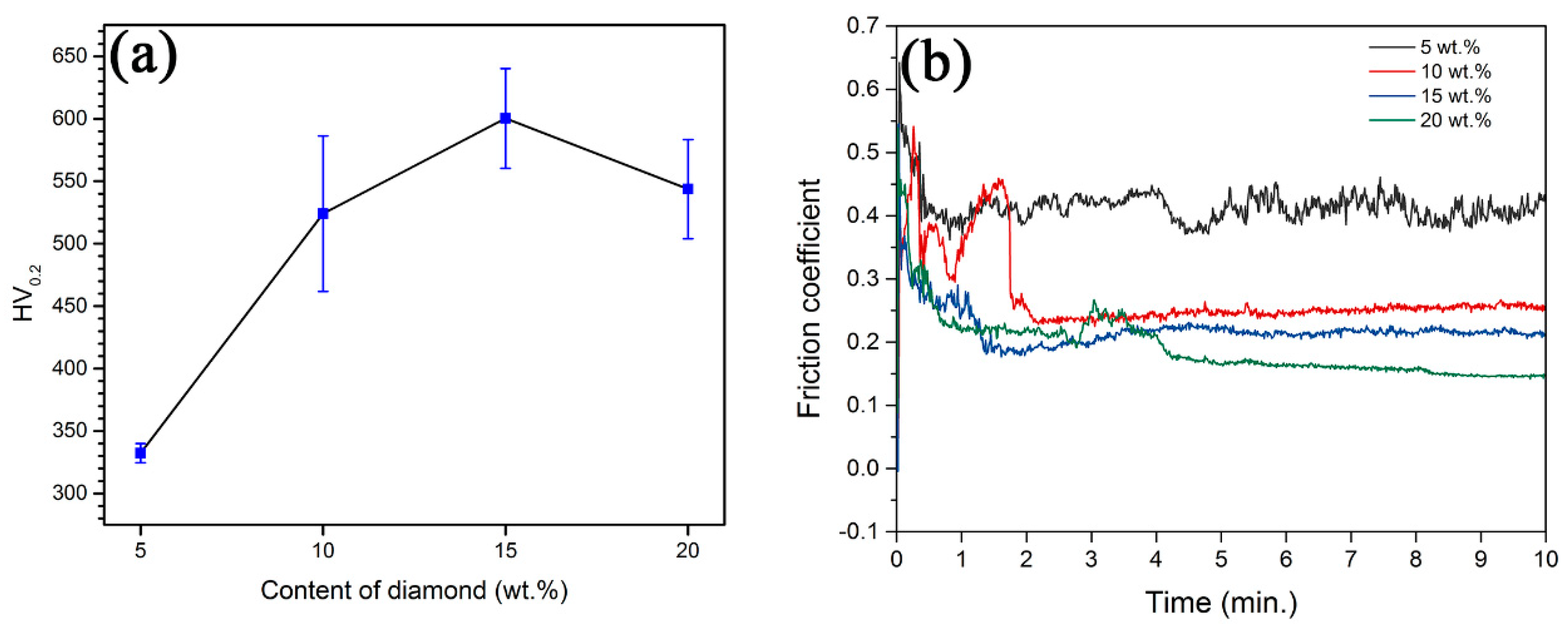
3.4.2. Mechanical Properties

Figure 12a shows the microhardness of FeCoCrNi-Mo/diamond composite coatings with different diamond addition. It can be seen that the microhardness of the composite coating increased first and then decreased, with the increase of diamond content. The hardness was the highest when diamond content was 15 wt.%. This is because the increase of diamond content improved the overall hardness of the composite coating. The C element diffused into the coating and formed the hard second phase such as chromium carbides and molybdenum carbides. Meanwhile, C also played the role of interstitial solution strengthening of the HEA matrix. Therefore, the coating was strengthened from many aspects, and the hardness of the coating was gradually improved. However, when the diamond addition was 20 wt.%, there were many micro-cracks in the composite coating, which released part of the internal stress, resulting in the decrease of microhardness of the coating.
The friction coefficient–time curves of the diamond composite coatings are shown in Figure 12b. When the diamond content was 5 wt.%, the initial friction coefficient of the coating was high, and the friction coefficient remained high after stabilization. With the increase of diamond content, the friction coefficient decreased and became more stable, showing better wear resistance.
Figure 13 shows the worn surface of the Si3N4 dual ball. With the increase of diamond content, the coating was obviously elevated in grinding effect, and the worn surface area of the dual ball became larger. However, when the diamond was 20 wt.%, due to the appearance of cracks in the coating, the peeling of the coating occurred during the friction process, and the grinding performance of the coating decreased, so the worn area of the dual ball surface decreased. When the diamond content of the coating was 10 wt.%, 15 wt.% and 20 wt.%, the worn area of the dual ball was 15.48, 18.19 and 16.63 mm2, respectively; compared with 12.82 mm2 of 5 wt.%, coatings with higher diamond content had good wear resistance and grinding effect.

4. Conclusions

  • FeCoCrNi-Mo HEA/diamond composite coatings with good wear resistance were successfully prepared by high speed laser cladding technology.
  • Micro-holes, cracks, and graphitization of diamond appeared and aggravated with the increase of laser power, resulting in the decrease of hardness and wear resistance. Too low a scanning speed increased the energy absorption of powder and the graphitization of diamond; too high a scanning speed resulted in the increase of un-melted HEA powders and poor bonding between HEA and the diamond.
  • When the high scanning speed of 50 mm/s and relatively low laser power of 3000 W was adopted, optimal microstructures and properties were obtained. Too high a scanning speed of 60 mm/s could not realize metallurgical bonding between the HEA matrix and diamond. At high laser power and low scanning speed, the diamond graphitized and lost the crystal shape, and diffused C reacted with Cr and Mo to form carbides.
  • With the increase of diamond content, the microstructures of the composite coating were obviously refined, and the wear resistance was improved. However, the high content (20 wt.%) aggravated the incompatibility of coating microstructures, resulting in microcracks. When the diamond content was 15 wt.%, optimal hardness and wear resistance were obtained.

Author Contributions

Conceptualization, W.Z.; methodology, W.Z.; validation, W.Z. and Y.P.; formal analysis, W.Z. and Y.P.; investigation, W.Z.; resources, Y.L.; data curation, M.Z., H.W. and S.L.; writing—original draft preparation, M.Z. and H.W.; writing—review and editing, W.Z. and Y.P.; supervision, Y.L.; project administration, W.Z. and Y.L.; funding acquisition, Y.L. All authors have read and agreed to the published version of the manuscript.

Funding

This research was funded by the project of State Key Laboratory of Powder Metallurgy (CSU 621011808), the National Natural Science Foundation of China (51731006), the Natural Science Foundation of Hunan Province (2020-2022 CSUZHANGWEI), the introduction projects of high-end foreign experts in 2019 for strategic science and technology development, Ministry of Science and Technology of the China (No: G20190010113), the Starting Research Fund of Nanjing Agricultural University (RCQD-1803).

Acknowledgments

The authors wish to acknowledge the financial support of State Key Laboratory of Powder Metallurgy (CSU 621011808), the National Natural Science Foundation of China (51731006), the Natural Science Foundation of Hunan Province (2020-2022 CSUZHANGWEI), the introduction projects of high-end foreign experts in 2019 for strategic science and technology development, Ministry of Science and Technology of the China (No: G20190010113), the Starting Research Fund of Nanjing Agricultural University (RCQD-1803).

Conflicts of Interest

The authors declare no conflict of interest.

References

  1. Fang, X.; Deng, F.; Zheng, R. Advanced Superabrasives and Related Products; Zhejiang University Press: Hangzhou, China, 2011. [Google Scholar]
  2. Wright, D.N.; Engels, J.A. The environmental and cost benefits of using diamond wire for quarrying and processing of natural stone. Ind. Diamond Rev. 2003, 4, 16–24. [Google Scholar]
  3. Wang, F.; Zhang, J.; Wang, Z. Current situation and development of diamond wire saw cutting technology. Diam. Abras. Eng. 2013, 33, 36–42. [Google Scholar]
  4. Zhang, Z.; Liu, B. Development of Diamond Rope Saw; West-China Exploration Engineering: Changchun, China, 1995. [Google Scholar]
  5. Li, H.; Feng, Y.; Yang, L. Hybrid diamond rope saw. CN Patent CN203305381U, 27 Noverber 2013. [Google Scholar]
  6. Weng, F.; Huang, G.; Huang, H. Study on sawing forces of sintered diamond wire-saw in granite cutting. Diam. Abras. Eng. 2007, 01, 25–27. [Google Scholar]
  7. Huang, X. Design of Deep-Water Diamond Wire Saw Machine and Research on Life Prediction of Beaded Wire. Master’s Thesis, Harbin Engineering University, Harbin, China, 2016. [Google Scholar]
  8. Wang, C.; Liu, H.; Zhang, X. Effect of laser power and heat treatment process on microstructure and property of multi-pass Ni based alloy laser cladding coating. In Proceedings of the SPIE-The International Society for Optical Engineering, Beijing, China, 16 November 2010. [Google Scholar] [CrossRef]
  9. Toyserkani, E.; Khajepour, A.; Corbin, S. Laser Cladding; CRC Press: Boca Raton, FL, USA, 2005. [Google Scholar]
  10. Sun, H.H.; Guo, M.H.; Meng, F.L. Studies on hard faced overlay of diamond grits reinforced Ni-based alloy fabricated by laser cladding. Trans. Indian Inst. Met. 2016, 69, 1369–1376. [Google Scholar] [CrossRef]
  11. Rommel, D.; Scherm, F.; Kuttner, C. Laser cladding of diamond tools: Interfacial reactions of diamond and molten metal. Surf. Coat. Technol. 2016, 291, 62–69. [Google Scholar] [CrossRef]
  12. Iravani, M.; Khajepour, A.; Corbin, S. Pre-placed laser cladding of metal matrix diamond composite on mild steel. Surf. Coat. Technol. 2012, 206, 2089–2097. [Google Scholar] [CrossRef]
  13. Yan, X.H.; Li, J.S.; Zhang, W.R. A brief review of high-entropy films. Mater. Chem. Phys. 2017, 210, 12–19. [Google Scholar] [CrossRef]
  14. Vaidya, M.; Pradeep, K.G.; Murty, B.S. Bulk tracer diffusion in CoCrFeNi and CoCrFeMnNi high entropy alloys. Acta Mater. 2018, 146, 211–224. [Google Scholar] [CrossRef]
  15. Verma, A.; Tarate, P.; Abhyankar, A.C. High temperature wear in CoCrFeNiCux high entropy alloys: The role of Cu. Scr. Mater. 2019, 161, 28–31. [Google Scholar] [CrossRef]
  16. Zhang, W.; Zhang, M.; Peng, Y. Effect of Ti/Ni coating of diamond particles on microstructure and properties of high-entropy alloy/diamond composites. Entropy 2019, 21, 164. [Google Scholar] [CrossRef] [Green Version]
  17. Huang, F. An investigation on microstructure and properties of Ni-based alloy by laser cladding and laser cladding forming. Ph.D. Thesis, Jilin University, Changchun, China, 2011. [Google Scholar]
  18. Zou, Q. Analysis of structures and surface states of nanodiamond and its treated methods. Master’s Thesis, Yanshan University, Qinhuangdao, China, 2004. [Google Scholar]
  19. Zhang, W.; Zhang, M.; Peng, Y. Interfacial structures and mechanical properties of a high entropy alloy-diamond composite. Int. J. Refract. Met. Hard Mater 2020, 86, 105109. [Google Scholar] [CrossRef]
  20. Li, Z. Interstitial equiatomic CoCrFeMnNi high-entropy alloys: carbon content, microstructure, and compositional homogeneity effects on deformation behavior. Acta Mater. 2019, 164, 400–412. [Google Scholar] [CrossRef]
  21. Liu, W.H.; Lu, Z.P.; He, J.Y.; Luan, J.H.; Wang, Z.J.; Liu, B.; Liu, Y.; Chen, M.W.; Liu, C.T. Ductile CoCrFeNiMox high entropy alloys strengthened by hard intermetallic phases. Acta Mater. 2016, 116, 332–342. [Google Scholar] [CrossRef]
  22. Peng, Y.; Zhang, W.; Mei, X. Microstructures and mechanical properties of FeCoCrNi-Mo High entropy alloys prepared by spark plasma sintering and vacuum hot-pressed sintering. Mater. Today Commun. 2020, 24, 101009. [Google Scholar] [CrossRef]
  23. Zhang, M.; Peng, Y.; Zhang, W. Gradient distribution of microstructures and mechanical properties in a FeCoCrNiMo high-entropy alloy during spark plasma sintering. Metals 2019, 9, 351. [Google Scholar] [CrossRef] [Green Version]
  24. Takeuchi, A.; Inoue, A. Classification of bulk metallic glasses by atomic size difference, heat of mixing and period of constituent elements and its application to characterization of the main alloying element. Mater. Trans. 2005, 46, 2817–2829. [Google Scholar] [CrossRef] [Green Version]
Figure 1. (a) Macro-morphology of FeCoCrNi-Mo/diamond composite coating prepared with different laser powers; (b) typical microstructure of coating (5000 W and 50 mm/s).
Coatings 10 00300 g001
Figure 2. Microstructure of longitudinal section with cross section inside of FeCoCrNi-Mo/diamond composite coatings with different laser powers at a scanning speed of 50 mm/s; (a) 3000 W; (b) 4000 W; (c) 5000 W; (d) 5500 W.
Coatings 10 00300 g002
Figure 3. The variation curve of physical parameters of FeCoCrNi-Mo/diamond composite coating with laser power; (a) dilution ratio; (b) width and height; (c) the schematic diagram for the calculation of dilution ratio of coating.
Coatings 10 00300 g003
Figure 4. Mechanical properties of FeCoCrNi-Mo/diamond composite coatings prepared with different laser powers: (a) microhardness; (b) friction coefficient–time curves.
Coatings 10 00300 g004
Figure 5. The wear morphology of FeCoCrNi-Mo/diamond composite coating was prepared by different laser powers; (a,b) 5500 W; (c,d) 5000 W; (e,f) 4000 W; (g,h) 3000 W.
Coatings 10 00300 g005
Figure 6. The microstructures of longitudinal section with cross section inside of FeCoCrNi-Mo/diamond composite coating was prepared at 3000 W laser power with different laser scanning speeds; (a) 60 mm/s; (b) 50 mm/s; (c) 40 mm/s; (d)30 mm/s.
Coatings 10 00300 g006
Figure 7. Frictional properties of FeCoCrNi-Mo/diamond composite coating. (a) The coefficient of friction; worn surface of dual ball by (b) 40 mm/s; (c) 50 mm/s.
Coatings 10 00300 g007
Figure 8. The morphology of diamond bonding in different laser energy density composite coating; (a) 3000 W and 50 mm/s; (b) 3000 W and 40 mm/s; (c) 5500 W and 50 mm/s; (d) 3000 W and 60 mm/s.
Coatings 10 00300 g008
Figure 9. The longitudinal section morphologies of the composite coatings with different diamond content; (a) 5 wt.%; (b) 10 wt.%; (c) 15 wt.%; (d) 20 wt.%.
Coatings 10 00300 g009
Figure 10. Microstructure of HEA matrix in composite coatings with different diamond content; (a) 5 wt.%; (b) 10 wt.%; (c) 15wt.%; (d) 20 wt.%.
Coatings 10 00300 g010
Figure 11. Microstructures of HEA/diamond coating. (a) The bonding area; (b) HEA matrix; (c) around diamond particles.
Coatings 10 00300 g011
Figure 12. Mechanical properties of composite coatings with different diamond content. (a) Microhardness; (b) the coefficient of friction.
Coatings 10 00300 g012
Figure 13. The wear morphology of the dual ball with different diamond content composite coating; (a) 10 wt.%; (b) 15 wt.%; (c) 20 wt.%.
Coatings 10 00300 g013
Table 1. The characteristics of FeCoCrNi-Mo/diamond composite coating prepared at different scanning speeds with laser power of 3000 W.
Scanning Speed (mm/s)Width (mm)Height (mm)Dilution Ratio (%)
604.020.320
503.880.33<10
402.770.3428.24
302.310.3343.58
Table 2. The grinding effect of composite coatings with different laser power and scanning speed.
Laser Power (W)Scanning Speed (mm/s)Grinding Effect
550050Bad
500050Bad
400050Bad
300050Good
300040Bad
300030Bad
300060Bad
Table 3. Composition (at.%) of different phases (average of three measurements).
PhaseFeCoCrNiMoC
Black phase12.018.2730.155.412.6541.50
Light grey phase19.5318.5022.4823.904.6521.34
Dark grey phase17.7119.585.7028.846.8823.36
White phase10.2317.928.9611.659.8739.90
Table 4. Mixing enthalpy between C and the alloying elements in HEA (kJ/mol) [24].
ElementFeCoCrNiMo
C−50−42−61−39−67

