Hard Quasicrystalline Coatings Deposited by HVOF Thermal Spray to Reduce Ice Accretion in Aero-Structures Components

Abstract
1. Introduction
- Active methods [9]: systems that use energy to avoid ice accretion on surfaces (anti-icing mode), or favor its detachment once it has accreted (de-icing mode). Many different methods are used to this end, such as pneumatic [10], electrothermal [11], hot air heating systems [12,13], or mechanical vibration [14], among others.
- Passive methods: systems and methods based on physicochemical principles that modify the composition and/or the morphology of the surface of the component, and do not require anything of an additional energy contribution. The validated methods for use in aeronautics have been mostly based in the application of anti-freeze chemicals over the sensitive surfaces on-ground, or protect them in the first stages of flights. Most of these chemicals are anti-freezing fluids, such as some organic liquids (i. e. glycols) which reduce the freezing temperature of the water.
- Low coefficient of friction [51]: there is published data that mainly correspond to dry scratch testing using various indenters with spherical tips, in which the values of the friction coefficient with diamond are as low as 0.05 under constant-load operations. Friction coefficients for cemented carbide, hardened steel and alumina tips are of the order of 0.20 [52].
- High hardness [53]: in ordered metals under strain, the atomic planes or layers slide past one another (movement of the dislocations), but in non-periodic structures, so such sliding is not possible, resulting in elevated hardness. For some QC materials, values within the 10 GPa range have been measured [54], comparing favorably with the hardness levels for heat-treated, tribological steel (high-speed steels and steels used for ball bearings).
- Low surface energy [55]: some QCs present a rather low surface energy, much lower than that of a typical clean metal, and lower than that of an oxidized metal (i.e., alumina) [56]. It has been proposed that this low surface energy is (at least in part) caused by the peculiar electronic structure of the material’s surface, characterized by a “pseudo-gap” (a reduction) in the density of states at the Fermi level [57]. This reduction causes a lack of empty places for electronic interactions with other surfaces or liquids as water. This pseudo-gap has been demonstrated by theoretical calculations and experimental results of Belin and Ferre, among others, and it is a universal characteristic of QCs [58].
- Roughness (Ra and Rz).
- Static contact angle (SCA), contact angle hysteresis (CAH) and Roll-off angle (RoA)
- Ice accretion.
- Ice adhesion.
- Al alloy AA6061 T6 commonly used in aeronautics.
- PTFE, a well-known anti-wetting, and anti-icing material, but with low hardness and strength, as well as a high wear rate, which limit its application in this field [65].
- Two commercially available polyurethane (PU) paints, certified to for aeronautical use in commercial aircrafts. One of them is not commercialized as anti-icing, but was used by Airbus during the studies carried within the EC project STORM, showing significantly reduced ice adhesion with respect to, e.g., bare metallic surfaces like titanium or aluminum [66]. The other one is an aeronautical standard paint without reported anti-icing properties.
2. Experimental Methods
2.1. Materials
2.2. Coating Application
2.3. Coating Characterization
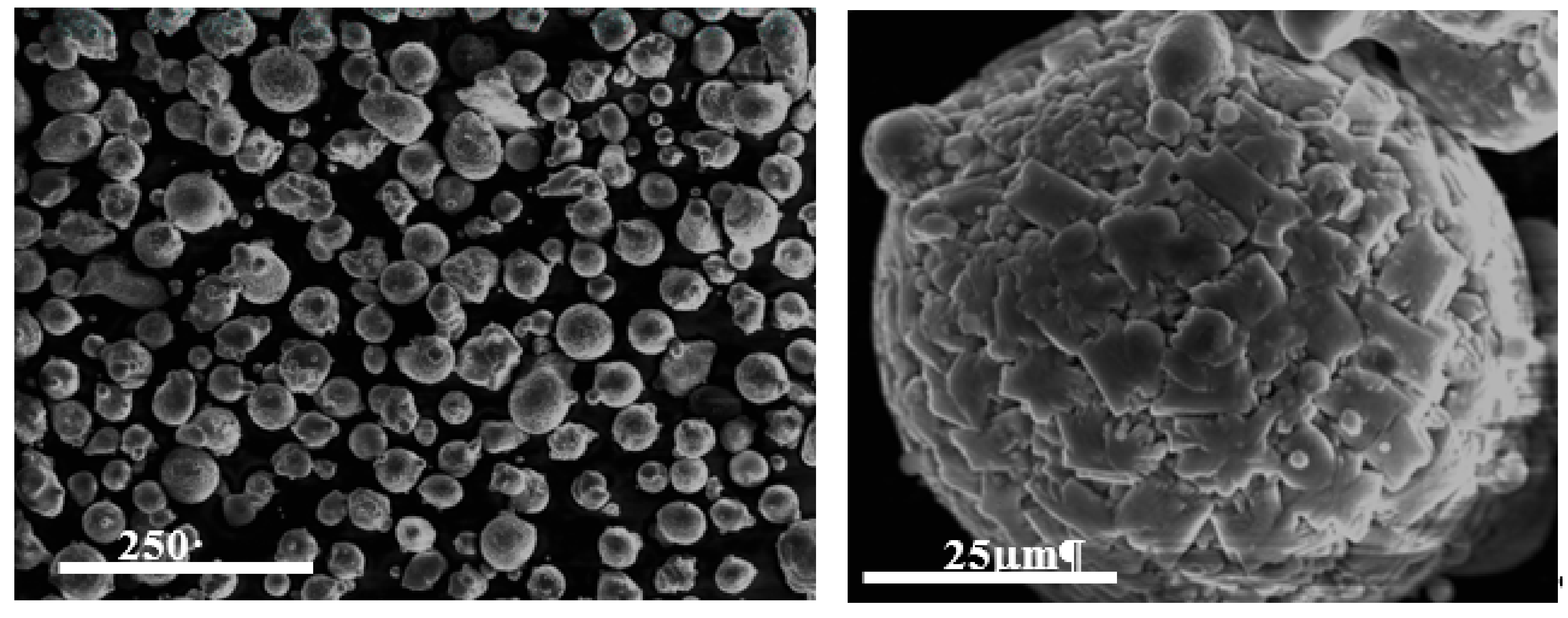
2.3.1. Microstructure
2.3.2. Roughness
2.3.3. Wetting Behavior
2.3.4. Hardness
2.4. Icing Wind Tunnel (IWT) Testing
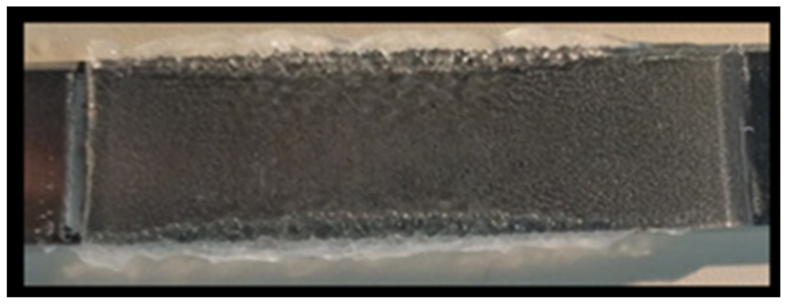
2.5. Ice adhesion by Double Lap Shear Test (DLST)
Test Procedure
3. Results and Discussion
3.1. Characterization of the Coatings
3.2. Ice Accretion
3.2.1. Rime Ice
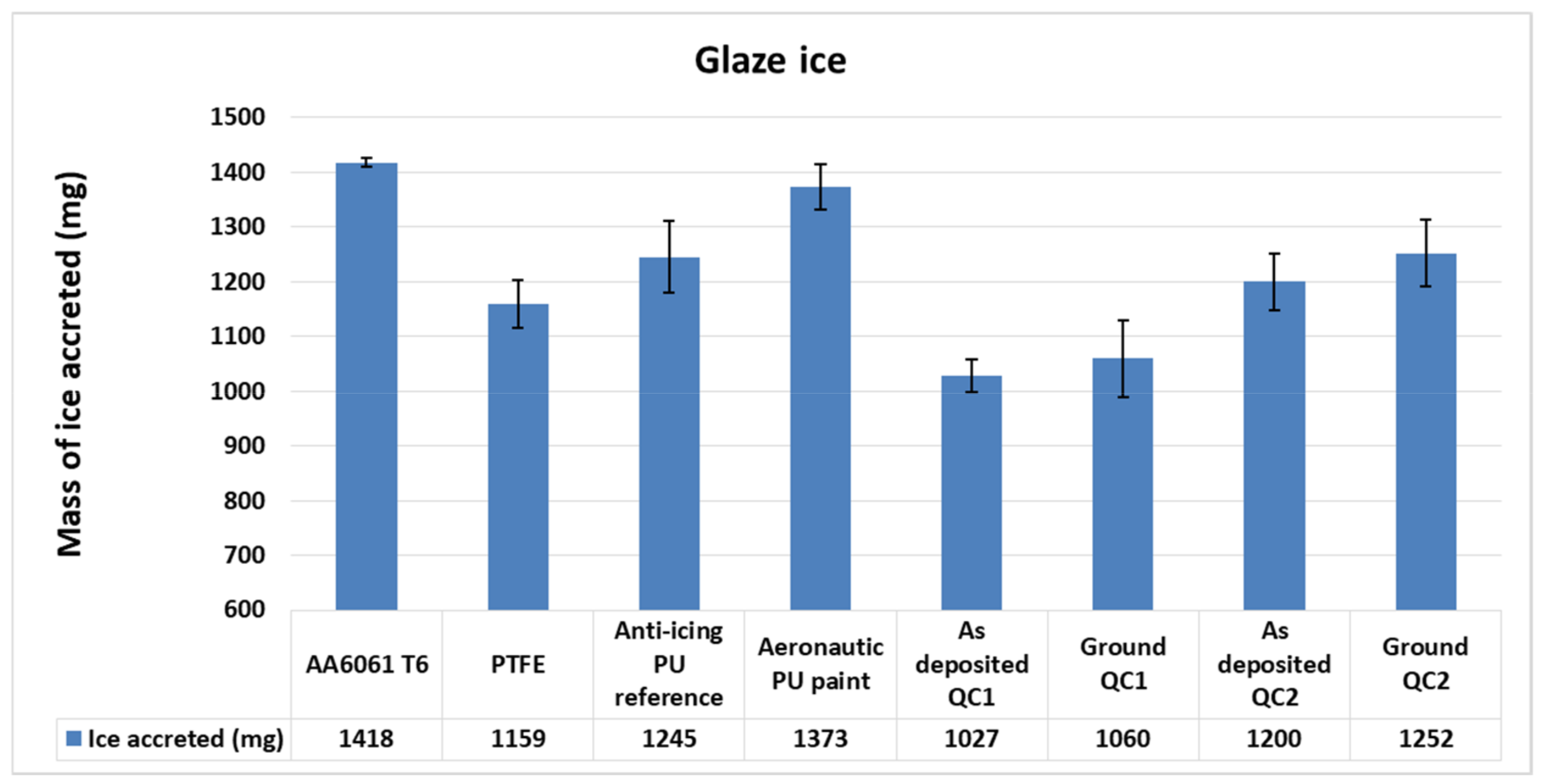
3.2.2. Glaze Ice
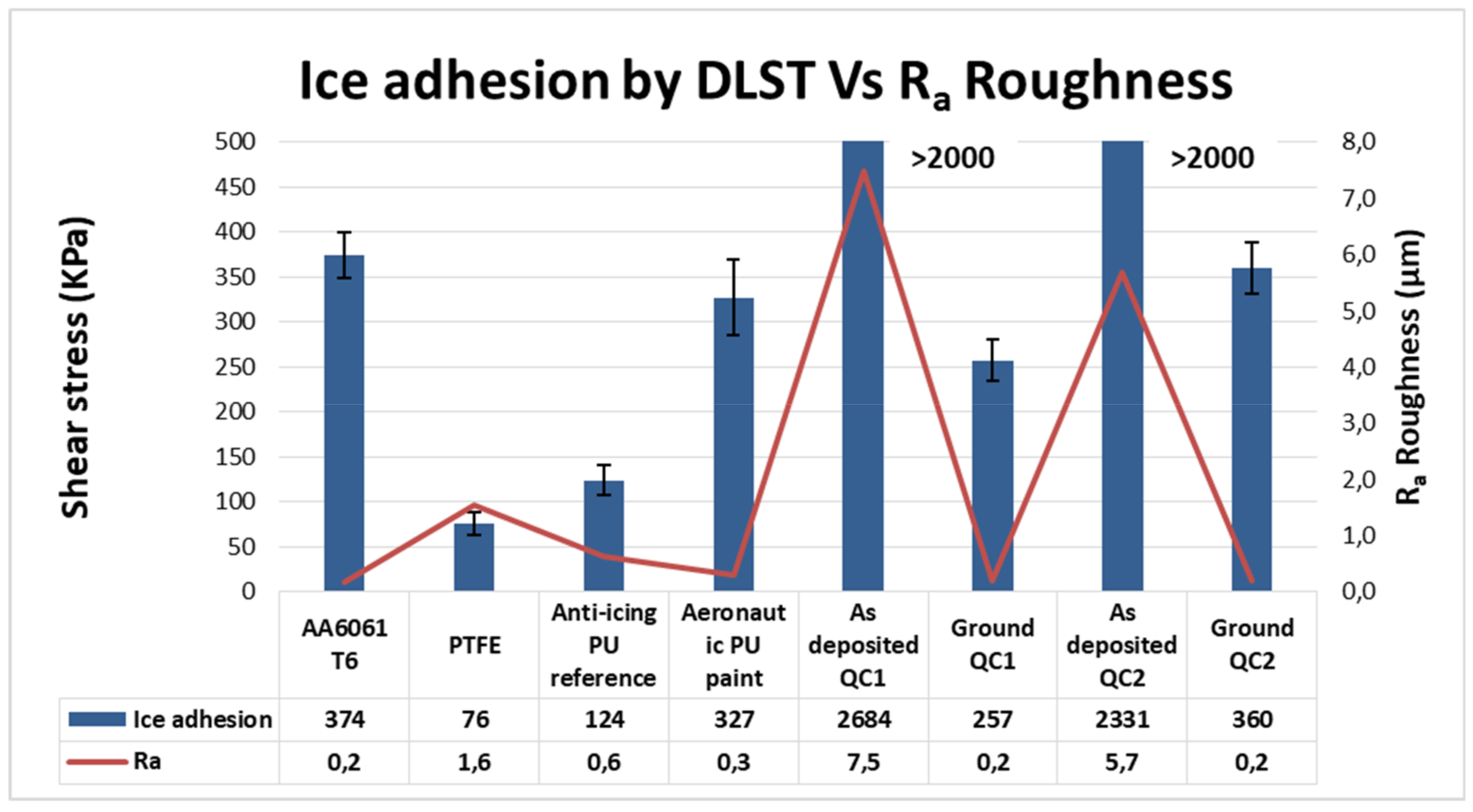
3.3. Ice Adhesion
3.4. Anti-Icing Performance Discussion
4. Conclusions
Author Contributions
Funding
Acknowledgments
Conflicts of Interest
References
- Isaac, G.A.; Cober, S.G.; Strapp, J.W.; Korolev, A.V.; Tremblay, A.; Marcotte, D.L. Recent Canadian research on aircraft in-flight icing. Can. Aeronaut. Space J. 2001, 47, 213–221. [Google Scholar]
- Mulherin, N.D.; Haehnel, R.B. Cold Reg. Res. Eng. Lab. Tech. 2003, 3, 9. [Google Scholar]
- Laforte, J.L.; Allaire, M.A.; Laflamme, J. State-of-the-art on power line de-icing. Atmos. Res. 1998, 46, 143–158. [Google Scholar] [CrossRef]
- Ratvasky, T.P.; Barnhart, B.P.; Lee, S. Current methods modeling and simulating icing effects on aircraft performance, stability, control. J. Aircr. 2010, 47, 201–211. [Google Scholar] [CrossRef]
- Mosher, F.R.; Schaum, D.; Herbster, C.; Guinn, T. Analysis of Causes of Icing Conditions which Contributed to the Crash of Continental Flight 3407; Embry-Riddle Aeronautical University: Daytona Beach, FL, USA, 2010. [Google Scholar]
- Politovich, M.K. Aircraft icing caused by large supercooled droplets. J. Appl. Meteorol. 1989, 28, 856–868. [Google Scholar] [CrossRef]
- Gent, R.W.; Dart, N.P.; Cansdale, J.T. Aircraft icing. Philosophical Transactions of the Royal Society of London. Ser. A Math. Phys. Eng. Sci. 2000, 358, 2873–2911. [Google Scholar] [CrossRef]
- Thomas, S.K.; Cassoni, R.P.; MacArthur, C.D. Aircraft anti-icing and de-icing techniques and modeling. J. Aircr. 1996, 33, 841–854. [Google Scholar] [CrossRef]
- Weisend, N.A., Jr. Inflatable airfoil device. U.S. Patent No. 6,443,394, 3 September 2002. [Google Scholar]
- Rutherford, R.B.; Dudman, R.L. Zoned aircraft de-icing system and method. U.S. Patent 6,237,874, 29 May 2002. [Google Scholar]
- Petrenko, V.F.; Sullivan, C.R.; Kozlyuk, V.; Petrenko, F.V.; Veerasamy, V. Pulse electro-thermal de-icer (PETD). Cold Reg. Sci. Technol. 2011, 65, 70–78. [Google Scholar] [CrossRef]
- Rudolph, P.K.; Georgefalvy, D. Anti-icing system for aircraft. U.S. Patent No. 5,114,100, 19 May 1992. [Google Scholar]
- Gornik, A. Mechanical vibration deicing system. U.S. Patent No. 8,517,313, 27 August 2013. [Google Scholar]
- Cornell, J.S.; Pillard, D.A.; Hernandez, M.T. Comparative measures of the toxicity of component chemicals in aircraft deicing fluid. Environ. Toxicol. Chem. Int. J. 2000, 19, 1465–1472. [Google Scholar] [CrossRef]
- Ramakrishna, D.M.; Viraraghavan, T. Environmental impact of chemical deicers–A review. Water Air Soil Pollut. 2005, 166, 49–63. [Google Scholar] [CrossRef]
- Cao, L.; Jones, A.K.; Sikka, V.K.; Wu, J.; Gao, D. Anti-icing superhydrophobic coatings. Langmuir 2009, 25, 12444–12448. [Google Scholar] [CrossRef]
- Honsek, R.; Habashi, W.G.; Aubé, M.S. Eulerian modeling of in-flight icing due to supercooled large droplets. J. Aircr. 2008, 45, 1290–1296. [Google Scholar] [CrossRef]
- Bulte, G.J. Lotus leaf with waterdrops, showing the ‘Lotus-effect’ [Figure]. Available online: https://commons.wikimedia.org/wiki/File:Lotus_leaf_with_waterdrops.jpg (accessed on 20 March 2020).
- Latthe, S.S.; Terashima, C.; Nakata, K.; Fujishima, A. Superhydrophobic surfaces developed by mimicking hierarchical surface morphology of lotus leaf. Molecules 2014, 19, 4256–4283. [Google Scholar] [CrossRef]
- Bhushan, B.; Her, E.K. Fabrication of superhydrophobic surfaces with high and low adhesion inspired from rose petal. Langmuir 2010, 26, 8207–8217. [Google Scholar] [CrossRef]
- Liu, K.; Du, J.; Wu, J.; Jiang, L. Superhydrophobic gecko feet with high adhesive forces towards water and their bio-inspired materials. Nanoscale 2012, 4, 768–772. [Google Scholar] [CrossRef]
- He, Y.; Jiang, C.; Cao, X.; Chen, J.; Tian, W.; Yuan, W. Reducing ice adhesion by hierarchical micro-nano-pillars. Appl. Surf. Sci. 2014, 305, 589–595. [Google Scholar] [CrossRef]
- Jung, S.; Dorrestijn, M.; Raps, D.; Das, A.; Megaridis, C.M.; Poulikakos, D. Are superhydrophobic surfaces best for ice-phobicity? Langmuir 2011, 27, 3059–3066. [Google Scholar] [CrossRef]
- Janjua, Z.A.; Turnbull, B.; Choy, K.L.; Pandis, C.; Liu, J.; Hou, X.; Choi, K.S. Performance and durability tests of smart ice-phobic coatings to reduce ice adhesion. Appl. Surf. Sci. 2017, 407, 555–564. [Google Scholar] [CrossRef]
- Hejazi, V.; Sobolev, K.; Nosonovsky, M. From superhydrophobicity to ice-phobicity: Forces and interaction analysis. Sci. Rep. 2013, 3, 2194. [Google Scholar] [CrossRef]
- Zou, M.; Beckford, S.; Wei, R.; Ellis, C.; Hatton, G.; Miller, M.A. Effects of surface roughness and energy on ice adhesion strength. Appl. Surf. Sci. 2011, 257, 3786–3792. [Google Scholar] [CrossRef]
- Matsumoto, K.; Kobayashi, T. Fundamental study on adhesion of ice to cooling solid surface. Int. J. Refrig. 2007, 30, 851–860. [Google Scholar] [CrossRef]
- Dotan, A.; Dodiuk, H.; Laforte, C.; Kenig, S. The relationship between water wetting and ice adhesion. J. Adhes. Sci. Technol. 2009, 23, 1907–1915. [Google Scholar] [CrossRef]
- Bascom, W.D.; Cottington, R.L.; Singleterry, C.R. Ice adhesion to hydrophilic and hydrophobic surfaces. J. Adhes. 1969, 1, 246–263. [Google Scholar] [CrossRef]
- Kulinich, S.A.; Farzaneh, M. How wetting hysteresis influences ice adhesion strength on superhydrophobic surfaces. Langmuir 2009, 25, 8854–8856. [Google Scholar] [CrossRef] [PubMed]
- Meuler, A.J.; Smith, J.D.; Varanasi, K.K.; Mabry, J.M.; McKinley, G.H.; Cohen, R.E. Relationships between water wettability and ice adhesion. ACS Appl. Mater. Interfaces 2010, 2, 3100–3110. [Google Scholar] [CrossRef]
- Jafari, R.; Menini, R.; Farzaneh, M. Superhydrophobic and ice-phobic surfaces prepared by RF-sputtered polytetrafluoroethylene coatings. Appl. Surf. Sci. 2010, 257, 1540–1543. [Google Scholar] [CrossRef]
- Spence, C.F. (Ed.) AIM-FAR, 1999: Aeronautical Information Manual/Federal Aviation Regulations; McGraw-Hill Companies: New York, NY, USA, 1998. [Google Scholar]
- Wong, T.S.; Kang, S.H.; Tang, S.K.; Smythe, E.J.; Hatton, B.D.; Grinthal, A.; Aizenberg, J. Bioinspired self-repairing slippery surfaces with pressure-stable omniphobicity. Nature 2011, 477, 443–447. [Google Scholar] [CrossRef]
- Bohn, H.F.; Federle, W. Insect aquaplaning: Nepenthes pitcher plants capture prey with the peristome, a fully wettable water-lubricated anisotropic surface. Proc. Natl. Acad. Sci. USA 2004, 101, 14138–14143. [Google Scholar] [CrossRef]
- Kim, P.; Wong, T.S.; Alvarenga, J.; Kreder, M.J.; Adorno-Martinez, W.E.; Aizenberg, J. Liquid-infused nanostructured surfaces with extreme anti-ice and anti-frost performance. ACS Nano 2012, 6, 6569–6577. [Google Scholar] [CrossRef]
- Wilson, P.W.; Lu, W.; Xu, H.; Kim, P.; Kreder, M.J.; Alvarenga, J.; Aizenberg, J. Inhibition of ice nucleation by slippery liquid-infused porous surfaces (SLIPS). Phys. Chem. Chem. Phys. 2013, 15, 581–585. [Google Scholar] [CrossRef]
- Irajizad, P.; Hasnain, M.; Farokhnia, N.; Sajadi, S.M.; Ghasemi, H. Magnetic slippery extreme ice-phobic surfaces. Nat. Commun. 2016, 7, 1–7. [Google Scholar] [CrossRef] [PubMed]
- Rosensweig, R.E. Ferrohydrodynamics; Dover Inc.: Mineola, NY, USA, 1997. [Google Scholar]
- Irajizad, P.; Farokhnia, N.; Ghasemi, H. Dispensing nano-pico droplets of ferrofluids. Appl. Phys. Lett. 2015, 107, 191601. [Google Scholar] [CrossRef]
- Jung, S.; Tiwari, M.K.; Doan, N.V.; Poulikakos, D. Mechanism of supercooled droplet freezing on surfaces. Nature communications 2012, 3, 1–8. [Google Scholar] [CrossRef] [PubMed]
- Boinovich, L.; Emelyanenko, A.M.; Korolev, V.V.; Pashinin, A.S. Effect of wettability on sessile drop freezing: When superhydrophobicity stimulates an extreme freezing delay. Langmuir 2014, 30, 1659–1668. [Google Scholar] [CrossRef]
- Arianpour, F.; Farzaneh, M.; Kulinich, S.A. Hydrophobic and ice-retarding properties of doped silicone rubber coatings. Appl. Surf. Sci. 2013, 265, 546–552. [Google Scholar] [CrossRef]
- Lv, J.; Song, Y.; Jiang, L.; Wang, J. Bio-inspired strategies for anti-icing. ACS Nano 2014, 8, 3152–3169. [Google Scholar] [CrossRef]
- Menini, R.; Farzaneh, M. Elaboration of Al2O3/PTFE ice-phobic coatings for protecting aluminum surfaces. Surf. Coat. Technol. 2009, 203, 1941–1946. [Google Scholar] [CrossRef]
- Laforte, C.; Beisswenger, A. International Workshop on Atmospheric Icing of Structure. In Proceedings of the 10th International Workshop on Atmospheric Icing of Structures, Montréal, QC, Canada, 12–16 June 2005. [Google Scholar]
- Golovin, K.; Kobaku, S.P.; Lee, D.H.; DiLoreto, E.T.; Mabry, J.M.; Tuteja, A. Designing durable ice-phobic surfaces. Sci. Adv. 2016, 2, e1501496. [Google Scholar] [CrossRef]
- Boinovich, L.B.; Emelyanenko, A.M.; Emelyanenko, K.A.; Modin, E.B. Modus operandi of protective and anti-icing mechanisms underlying the design of longstanding outdoor ice-phobic coatings. ACS Nano 2019, 13, 4335–4346. [Google Scholar] [CrossRef]
- Dubois, J.M.; Kang, S.S.; Perrot, A. Towards applications of quasicrystals. Mater. Sci. Eng. A 1994, 179, 122–126. [Google Scholar] [CrossRef]
- Brunet, P.; Zhang, L.M.; Sordelet, D.J.; Besser, M.; Dubois, J.M. Comparative study of microstructural and tribological properties of sintered, bulk icosahedral samples. Mater. Sci. Eng. A 2000, 294, 74–78. [Google Scholar] [CrossRef]
- Dubois, J.M.; Goldman, A.I.; Sordelet, D.J.; Thiel, P.A. New Horizons in Quasicrystals: Research and Applications; Goldman, A.I., Sordelet, D.J., Thiel, P.A., Eds.; World Scientific Publishing Company: Singapore, 1997; pp. 208–215. [Google Scholar]
- Wolf, B.; Bambauer, K.O.; Paufler, P. On the temperature dependence of the hardness of quasicrystals. Mater. Sci. Eng. A 2001, 298, 284–295. [Google Scholar] [CrossRef]
- Kang, S.S.; Dubois, J.M. Pressure-induced phase transitions in quasi-crystals and related compounds. EPL Europhys. Lett. 1992, 18, 45. [Google Scholar] [CrossRef]
- Belin-Ferré, E.; Dubois, J.M.; Fournée, V.; Brunet, P.; Sordelet, D.J.; Zhang, L.M. About the Al 3p density of states in Al–Cu–Fe compounds and its relation to the compound stability and apparent surface energy of quasicrystals. Mater. Sci. Eng. A 2000, 294, 818–821. [Google Scholar] [CrossRef]
- Jenks, C.J.; Thiel, P.A. Quasicrystals: A short review from a surface science perspective. Langmuir 1998, 14, 1392–1397. [Google Scholar] [CrossRef]
- Rivier, N.; Goldman, A.I.; Sordelet, D.J.; Thiel, P.A.; Dubois, J.M. Physical Properties of Quasicrystals; World Scientific: Singapore, 1997; pp. 188–199. [Google Scholar]
- Belin-Ferre, E. Quasicrystals: Current Topics. MRS Online Proceedings Library Archive 553 1998, 347–358. [Google Scholar]
- Van Blaaderen, A. Quasicrystals from nanocrystals. Nature 2009, 461, 892–893. [Google Scholar] [CrossRef]
- Zhang, F.; Robinson, B.W.; de Villiers-Lovelock, H.; Wood, R.J.; Wang, S.C. Wettability of hierarchically-textured ceramic coatings produced by suspension HVOF spraying. J. Mater. Chem. A 2015, 3, 13864–13873. [Google Scholar] [CrossRef]
- Sharifi, N.; Ettouil, F.B.; Moreau, C.; Dolatabadi, A.; Pugh, M. Engineering surface texture and hierarchical morphology of suspension plasma sprayed TiO2 coatings to control wetting behavior and superhydrophobic properties. Surf. Coat. Technol. 2017, 329, 139–148. [Google Scholar] [CrossRef]
- Qiao, J.H.; Jin, X.; Qin, J.H.; Liu, H.T.; Luo, Y.; Zhang, D.K. A super-hard superhydrophobic Fe-based amorphous alloy coating. Surf. Coat. Technol. 2018, 334, 286–291. [Google Scholar] [CrossRef]
- Koivuluoto, H.; Stenroos, C.; Kylmälahti, M.; Apostol, M.; Kiilakoski, J.; Vuoristo, P. Anti-icing behavior of thermally sprayed polymer coatings. J. Therm. Spray Technol. 2017, 26, 150–160. [Google Scholar] [CrossRef]
- Xi, N.; Liu, Y.; Zhang, X.; Liu, N.; Fu, H.; Hang, Z.; Gao, W. Steady anti-icing coatings on weathering steel fabricated by HVOF spraying. Appl. Surf. Sci. 2018, 444, 757–762. [Google Scholar] [CrossRef]
- Yan, Y.; Jia, Z.; Yang, Y. Preparation and mechanical properties of PTFE/nano-EG composites reinforced with nanoparticles. Procedia Environ. Sci. 2011, 10, 929–935. [Google Scholar] [CrossRef]
- Bonaccurso, E.; Pervier, M.; Pervier, H.; Campazzi, E.; Linassier, G.; Goncalves, E.; Balland, M.; Suel, S. Deliverable 5.4. STORM-FP7-605180 2017. [Google Scholar]
- Macdougall, G.; Ockrent, C. Surface energy relations in liquid/solid systems I. The adhesion of liquids to solids and a new method of determining the surface tension of liquids. Proc. R. Soc. Lond. Ser. A Math. Phys. Sci. 1942, 180, 151–173. [Google Scholar]
- SAE Aerospace Recommended Practice (ARP). Calibration and Acceptance of Icing Wind Tunnels; SAE: Warrendale, PA, USA, 2015. [Google Scholar]
- Goswami, S.; Klaus, S.; Benziger, J. Wetting and absorption of water drops on Nafion films. Langmuir 2008, 24, 8627–8633. [Google Scholar] [CrossRef] [PubMed]
- De Pauw, D.; Dolatabadi, A. Effect of superhydrophobic coating on the anti-icing and deicing of an airfoil. J. Aircr. 2017, 54, 490–499. [Google Scholar] [CrossRef]
- Mangini, D.; Antonini, C.; Marengo, M.; Amirfazli, A. Runback ice formation mechanism on hydrophilic and superhydrophobic surfaces. Cold Reg. Sci. Technol. 2015, 109, 53–60. [Google Scholar] [CrossRef]
- Morita, K.; Okamoto, K.; Aoki, A.; Kimura, S.; Sakaue, H. Hydrophobic Coating Study for Anti-Icing Aircraft; No. 2011-38-0010; SAE Technical Paper: Warrendale, PA, USA, 2011. [Google Scholar]
- Ozbay, S.; Erbil, H.Y. Ice accretion by spraying supercooled droplets is not dependent on wettability and surface free energy of substrates. Colloids Surf. A Physicochem. Eng. Asp. 2016, 504, 210–218. [Google Scholar] [CrossRef]
- Sharifi, N.; Dolatabadi, A.; Pugh, M.; Moreau, C. Anti-icing performance and durability of suspension plasma sprayed TiO2 coatings. Cold Reg. Sci. Technol. 2019, 159, 1–12. [Google Scholar] [CrossRef]
- ISO. Atmospheric Icing of Structures; International Standard; ISO: Geneva, Switzerland, 2001; p. 12494. [Google Scholar]
- Antonini, C.; Innocenti, M.; Horn, T.; Marengo, M.; Amirfazli, A. Understanding the effect of superhydrophobic coatings on energy reduction in anti-icing systems. Cold Reg. Sci. Technol. 2011, 67, 58–67. [Google Scholar] [CrossRef]
- Ferrick, M.G.; Mulherin, N.D.; Haehnel, R.B.; Coutermarsh, B.A.; Durell, G.D.; Tantillo, T.J.; Welser, E.S.; Cano, R.J.; Smith, R.J.; Martinez, E.C. Double Lap Shear Testing of Coating Modified Ice Adhesion to Liquid Oxygen Food Line Bracket, Space Shuttle External Tank; No. ERDC/CRREL-TR-06-11; Engineering Research and Development Center Hanover nh cold Regions Research and Engineering Lab: Hanover, NH, USA, 2006. [Google Scholar]
- Kimura, S.; Yamagishi, Y.; Sakabe, A.; Adachi, T.; Shimanuki, M. A New Surface Coating for Prevention of Icing on Airfoils; No. 2007-01-3315; SAE Technical Paper: Warrendale, PA, USA, 2007. [Google Scholar]
- Menini, R.; Ghalmi, Z.; Farzaneh, M. Highly resistant ice-phobic coatings on aluminum alloys. Cold Reg. Sci. Technol. 2011, 65, 65–69. [Google Scholar] [CrossRef]
- Karmouch, R.; Coudé, S.; Abel, G.; Ross, G.G. Ice-phobic PTFE coatings for wind turbines operating in cold climate conditions. In Proceedings of the 2009 IEEE Electrical Power & Energy Conference (EPEC), Montreal, QC, Canada, 22–23 October 2009; pp. 1–6. [Google Scholar]
- Chen, J.; Liu, J.; He, M.; Li, K.; Cui, D.; Zhang, Q.; Song, Y. Superhydrophobic surfaces cannot reduce ice adhesion. Appl. Phys. Lett. 2012, 101, 111603. [Google Scholar] [CrossRef]
- Yeong, Y.H.; Loth, E.; Sokhey, J.; Lambourne, A. Ice Adhesion Performance of Superhydrophobic Coatings in Aerospace Icing Conditions; No. 2015-01-2120; SAE Technical Paper: Warrendale, PA, USA, 2015. [Google Scholar]


| Hardness (Hv) | Coefficient of Friction (Unlubricated, with a Diamond Pin) | Surface Energy (mJ/m2) | |||
|---|---|---|---|---|---|
| Material | Value | Material | Value | Material | Value |
| Diamond | 6000–10000 | Copper | 0.42 | Iron (clean) | 2480 |
| Silica | 750–1200 | Aluminum alloy | 0.37 | Copper (clean) | 1830 |
| i-Al-Cu-Fe | 800–1000 | Low-carbon steel | 0.32 | Alumina | 50 |
| i-Al-Pd-Mn | 700–800 | i-Al–Cu–Fe | 0.05–0.2 | i-Al-Pd-Mn | 24–25 |
| Aluminum | 25–45 | ||||
| Denomination | Company | Powder Size (µm) | Composition (wt %) | Commercial Name |
|---|---|---|---|---|
| QC1 | SAINT GOBAIN | +20 −75 | 54.1 Al; 17.9 Cu; 13.7 Fe; 14.3 Cr | CRISTOME A1/S |
| QC2 | SAINT GOBAIN | +25 −63 | 48.8 Al; 40.2 Cu; 19.1 Fe + 0.9 B | CRISTOME F1 |
| Denomination | Oxygen (l/min) | Hydrogen (l/min) | Nitrogen (l/min) | Powder Feeder Rate (g/min) | Spray Distance (mm) | Transverse Speed (mm/s) |
|---|---|---|---|---|---|---|
| QC1 | 180 | 344 | 635 | 25 | 360 | 1691 |
| QC2 | 214 | 344 | 635 | 25 | 300 | 1691 |
| Conditions | Glaze Ice | Rime Ice |
|---|---|---|
| Wind speed (m/s) | 50 | 50 |
| Temperature (°C) | −10 | −20 |
| MVD (μm) | 20 | 20 |
| LMC (g/m3) | 0.5 | 0.5 |
| Type of Ice | Density Range (kg/m3) |
|---|---|
| Glaze | 900 |
| Wet snow | 300–600 |
| Hard Rime | 600–900 |
| Soft Rime | 200–600 |
© 2020 by the authors. Licensee MDPI, Basel, Switzerland. This article is an open access article distributed under the terms and conditions of the Creative Commons Attribution (CC BY) license (http://creativecommons.org/licenses/by/4.0/).
Share and Cite
Mora, J.; García, P.; Muelas, R.; Agüero, A. Hard Quasicrystalline Coatings Deposited by HVOF Thermal Spray to Reduce Ice Accretion in Aero-Structures Components. Coatings 2020, 10, 290. https://doi.org/10.3390/coatings10030290
Mora J, García P, Muelas R, Agüero A. Hard Quasicrystalline Coatings Deposited by HVOF Thermal Spray to Reduce Ice Accretion in Aero-Structures Components. Coatings. 2020; 10(3):290. https://doi.org/10.3390/coatings10030290
Chicago/Turabian StyleMora, J., P. García, R. Muelas, and A. Agüero. 2020. "Hard Quasicrystalline Coatings Deposited by HVOF Thermal Spray to Reduce Ice Accretion in Aero-Structures Components" Coatings 10, no. 3: 290. https://doi.org/10.3390/coatings10030290
APA StyleMora, J., García, P., Muelas, R., & Agüero, A. (2020). Hard Quasicrystalline Coatings Deposited by HVOF Thermal Spray to Reduce Ice Accretion in Aero-Structures Components. Coatings, 10(3), 290. https://doi.org/10.3390/coatings10030290