Cu–MoS2 Superhydrophobic Coating by Composite Electrodeposition

Abstract
1. Introduction
2. Materials and Methods
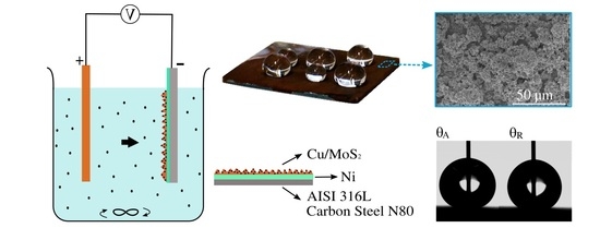
2.1. Sample Preparation and Cu–MoS2 Coating
2.2. Electrophoretic Deposition of a MoS2 Coating
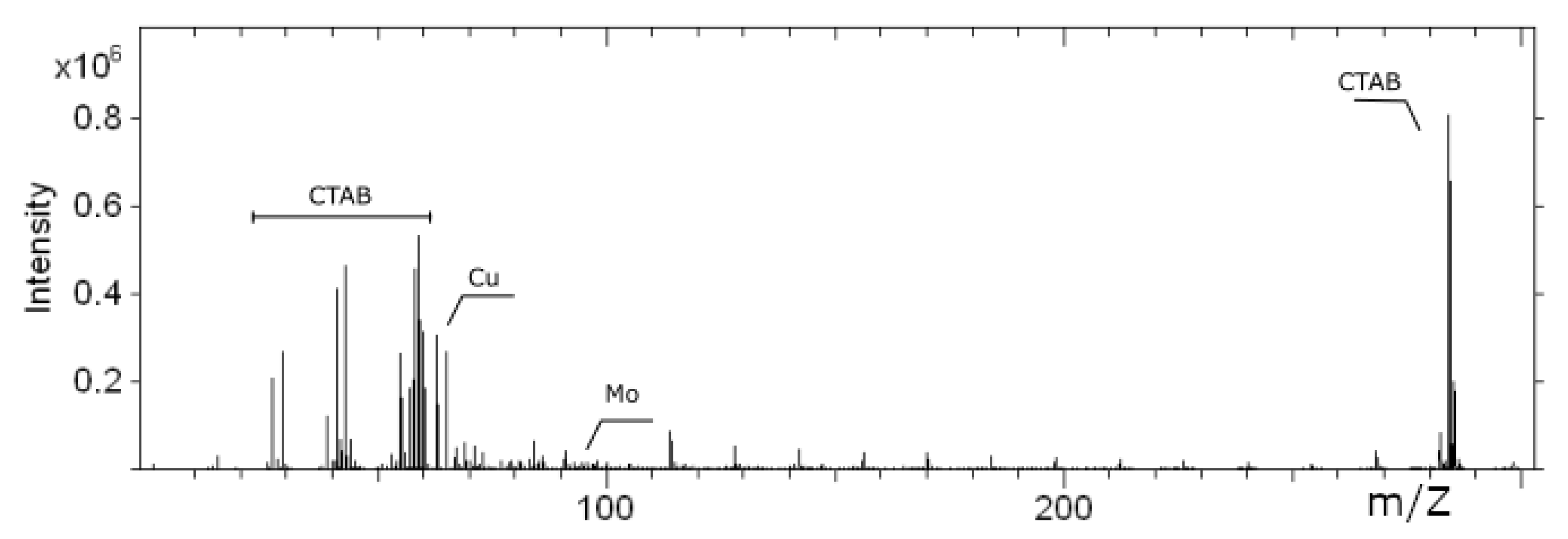
2.3. Sample Characterization
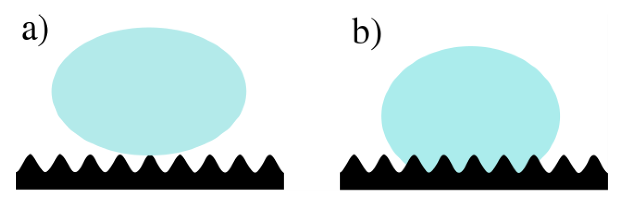
2.4. Wettability Characterization
2.5. Electrochemical Analysis
- Stainless steel AISI 316L
- Carbon steel N80
- Stainless steel AISI 316L coated by EPD with MoS2 particles
- Stainless steel coated with a thin Ni layer and a Cu layer
- Stainless steel AISI 316L with a thin Ni layer and a Cu–MoS2 composite coating
3. Results and Discussion
4. Conclusions
Supplementary Materials
Author Contributions
Funding
Acknowledgments
Conflicts of Interest
References
- Zhang, D.; Wang, L.; Qian, H.; Li, X. Superhydrophobic surfaces for corrosion protection: A review of recent progresses and future directions. J. Coat. Technol. Res. 2016, 13, 11–29. [Google Scholar] [CrossRef]
- Zhang, X.; Shi, F.; Niu, J.; Jiang, Y.; Wang, Z. Superhydrophobic surfaces: From structural control to functional application. J. Mater. Chem. 2007, 18, 621–633. [Google Scholar] [CrossRef]
- Law, K.Y.; Zhao, H. Surface Wetting: Characterization, Contact Angle, and Fundamentals; Springer: Cham, Switzerland, 2016; pp. 25–26. [Google Scholar]
- Li, X.M.; Reinhoudt, D.; Crego-Calama, M. What do we need for a superhydrophobic surface? A review on the recent progress in the preparation of superhydrophobic surfaces. Chem. Soc. Rev. 2007, 36, 1350–1368. [Google Scholar] [CrossRef]
- Gao, L.; McCarthy, T.J. Wetting 101. Langmuir 2009, 25, 14105–14115. [Google Scholar] [CrossRef]
- Mohamed, A.M.A.; Abdullah, A.M.; Younan, N.A. Corrosion behavior of superhydrophobic surfaces: A review. Arab. J. Chem. 2015, 8, 749–765. [Google Scholar] [CrossRef]
- Liu, S.; Liu, X.; Latthe, S.S.; Gao, L.; An, S.; Yoon, S.S.; Liu, B.; Xing, R. Self-cleaning transparent superhydrophobic coatings through simple sol-gel processing of fluoroalkylsilane. Appl. Surf. Sci. 2015, 351, 897–903. [Google Scholar] [CrossRef]
- Castaneda-Montes, I.; Ritchie, A.W.; Badyal, J.P.S. Atomised spray plasma deposition of hierarchical superhydrophobic nanocomposite surfaces. Colloid Surf. A 2018, 558, 192–199. [Google Scholar] [CrossRef]
- Milles, S.; Soldera, M.; Voisiat, B.; Lasagni, A.F. Fabrication of superhydrophobic and ice-repellent surfaces on pure aluminium using single and multiscaled periodic textures. Sci. Rep. 2019, 9, 13944. [Google Scholar] [CrossRef]
- Cai, Y.; Chang, W.; Luo, X.; Sousa, A.M.L.; Lau, K.H.A.; Qin, Y. Superhydrophobic structures on 316L stainless steel surfaces machined by nanosecond pulsed laser. Precis. Eng. 2018, 52, 266–275. [Google Scholar] [CrossRef]
- Pou, P.; del Val, J.; Riveiro, A.; Comesaña, R.; Arias-Gonzáleza, F.; Lusquiños, F.; Bountinguiza, M.; Quintero, F.; Pou, J. Laser texturing of stainless steel under different processing atmospheres: From superhydrophilic to superhydrophobic surfaces. Appl. Surf. Sci. 2019, 475, 896–905. [Google Scholar] [CrossRef]
- Low, C.T.J.; Wills, R.G.A.; Walsh, F.C. Electrodeposition of composite coatings containing nanoparticles in a metal deposit. Surf. Coat. Technol. 2006, 201, 371–383. [Google Scholar] [CrossRef]
- Kerr, C.; Barker, D.; Walsh, F.; Archer, J. The Electrodeposition of Composite Coatings based on Metal Matrix-Included Particle Deposits. Trans. IMF 2000, 78, 171–178. [Google Scholar] [CrossRef]
- Walsh, F.C.; Ponce de Leon, C. A review of the electrodeposition of metal matrix composite coatings by inclusion of particles in a metal layer: An established and diversifying technology. Trans. IMF 2014, 92, 83–98. [Google Scholar] [CrossRef]
- Zhao, G.; Xue, Y.; Huang, Y.; Ye, Y.; Walsh, F.C.; Chen, J.; Wang, S. One-step electrodeposition of a self-cleaning and corrosion resistant Ni/WS2 superhydrophobic surface. RSC Adv. 2016, 6, 59104–59112. [Google Scholar] [CrossRef]
- Zhao, G.; Li, J.; Huang, Y.; Yang, L.; Ye, Y.; Walsh, F.C.; Chen, J.; Wang, S. Robust Ni/WC superhydrophobic surfaces by electrodeposition. RSC Adv. 2017, 7, 44896–44903. [Google Scholar] [CrossRef]
- Furlan, K.P.; de Mello, J.D.B.; Klein, A.N. Self-lubricating composites containing MoS2: A review. Tribol. Int. 2018, 120, 280–298. [Google Scholar] [CrossRef]
- Stankovic, V.D.; Gojo, M. Electrodeposited composite coatings of copper with inert, semiconductive and conductive particles. Surf. Coat. Technol. 1996, 81, 225–232. [Google Scholar] [CrossRef]
- McGovern, I.T.; Dietz, E.; Rotermund, H.H.; Bradshaw, A.M.; Braun, W.; Radlik, W.; McGilp, J.F. Soft X-ray photoemission spectroscopy of metal-molybdenum bisulphide interfaces. Surf. Sci. 1985, 152/153, 1203–1212. [Google Scholar] [CrossRef]
- Panitz, J.K.G.; Dugger, M.T.; Peebles, D.E.; Tallant, D.R.; Hills, C.R. Electrophoretic deposition of pure MoS2 dry film lubricant coatings. J. Vac. Sci. Technol. A 1993, 11, 1441–1446. [Google Scholar] [CrossRef]
- Stepanov, A.A.; Esenin, V.N.; Golub, A.S.; Lenenko, N.D.; Makhonina, E.V.; Pervov, V.S.; Novikov, Y.N. Characteristics of electrodeposition of composite coatings based on nanosized molybdenum disulfide and copper. Russ. J. Inorg. Chem. 2008, 53, 686–689. [Google Scholar] [CrossRef]
- Kang, M.S.; Kim, S.K.; Kim, J.J. A novel process to control the surface roughness and resistivity of electroplated Cu using thiourea. Jpn. J. Appl. Phys. 2005, 44, 8107–8109. [Google Scholar] [CrossRef]
- Sun, M.; O’Keefe, T.J. The effect of additives on the nucleation and growth of copper onto stainless steel cathodes. MTB 1992, 23B, 591–599. [Google Scholar] [CrossRef]
- Yuliy, D.; Gamburg, G.Z. Theory and Practice of Metal Electrodeposition; Springer: New York, NY, USA, 2011; pp. 1–25. [Google Scholar]
- Quinet, M.; Lallemand, F.; Ricq, L.; Hihn, J.Y.; Delobelle, P.; Arnould, C.; Mekhalif, Z. Influence of organic additives on the initial stages of copper electrodeposition on polycrystalline platinum. Electrochim. Acta 2009, 54, 1529–1536. [Google Scholar] [CrossRef]
- Kang, M.S.; Kim, S.K.; Kim, K.; Kim, J.J. The influence of thiourea on copper electrodeposition: Adsorbate identification and effect on electrochemical nucleation. Thin Solid Films 2008, 516, 3761–3766. [Google Scholar] [CrossRef]
- Piro, O.E.; Piatti, R.C.V.; Bolzán, A.E.; Salvarezza, R.C.; Arvia, A.J. X-ray diffraction study of copper (I) thiourea complexes formed in sulfate-containing acid solutions. Acta Cryst. 2000, B56, 993–997. [Google Scholar] [CrossRef]
- Doona, C.J.; Stanbury, D.M. Equilibrium and Redox Kinetics of Copper (II)−Thiourea Complexes. Inorg. Chem. 1996, 35, 3210–3216. [Google Scholar] [CrossRef] [PubMed]
- Suarez, D.F.; Olson, F.A. Nodulation of electrodeposited copper in the presence of thiourea. J. Appl. Electrochem. 1992, 22, 1002–1010. [Google Scholar] [CrossRef]
- Alodan, M.; Smyrl, W. Effect of thiourea on copper dissolution and deposition. Electrochim. Acta 1998, 44, 299–309. [Google Scholar] [CrossRef]
- Huhtamäki, T.; Tian, X.; Korhonen, J.T.; Ras, R.H.A. Surface-wetting characterization using contact-angle measurements. Nat. Protoc. 2018, 13, 1521–1538. [Google Scholar] [CrossRef]
- Van Ham, R.; Van Vaeck, L.; Adams, F.C.; Adriaens, A. Systematization of the Mass Spectra for Speciation of Inorganic Salts with Static Secondary Ion Mass Spectrometry. Anal. Chem. 2004, 76, 2609–2617. [Google Scholar] [CrossRef]
- Van Royen, P.; Schacht, E.; Ruys, L.; Van Vaeck, L. Static secondary ion mass spectrometry for nanoscale analysis: Surface characterisation of electro spun nanofibers. Rapid Commun. Mass Spectrom. 2006, 20, 346–352. [Google Scholar] [CrossRef]
- Bobji, M.S.; Kumar, S.V.; Asthana, A.; Govardhan, R.N. Underwater Sustainability of the “Cassie” State of Wetting. Langmuir 2009, 25, 12120–12126. [Google Scholar] [CrossRef] [PubMed]
- Benck, J.D.; Hellstern, T.R.; Kibsgaard, J.; Chakthranont, P.; Jaramillo, T.F. Catalyzing the Hydrogen Evolution Reaction (HER) with Molybdenum Sulfide Nanomaterials. ACS Catal. 2014, 4, 3957–3971. [Google Scholar] [CrossRef]
- Fateh, A.; Aliofkhazraei, M.; Rezvanian, A.R. Review of corrosive environments for copper and its corrosion inhibitors. Arab. J. Chem. 2020, 13, 481–544. [Google Scholar] [CrossRef]


| Element | C | Si | Mn | Ni | Cr | Mo | S | P | Fe |
|---|---|---|---|---|---|---|---|---|---|
| SS 316L | <0.03 | <1 | <2 | 10 | 18 | 3 | <0.03 | <0.45 | Balance |
| CS N80 | 0.31 | 0.19 | 0.92 | – | 0.20 | – | 0.08 | 0.01 | Balance |
| Components | Composition |
|---|---|
| CuSO4∙H2O | 0.641 M |
| H2SO4 | 0.489 M |
| Thiourea | 5 × 10⁻⁴ M |
| MoS2 (2 µm particles) | 2.5, 5, 10, 15, 20 g/L |
| CTAB | 0.1 g/g MoS2 |
| Electrodeposition Parameters | Values |
|---|---|
| Current Density | 40, 50, 60 mA/cm2 |
| Time | 1, 2, 3, 5 min |
| Stirring | 200 rpm |
| Temperature | Room temperature |
| Substrate | MoS2 in Solution (g/L) | Current Density (mA/cm²) | Time (min) | σ A (°) | σθA | θR (°) | σθA | CA Hysteresis (°) |
|---|---|---|---|---|---|---|---|---|
| SS 316L | 10.0 | 50.0 | 2.0 | 158.2 | 0.8 | 151.3 | 0.9 | 1.8 |
| CS N80 | 10.0 | 90.0 | 2.0 | 151.6 | 0.4 | 149.6 | 0.3 | 2.0 |
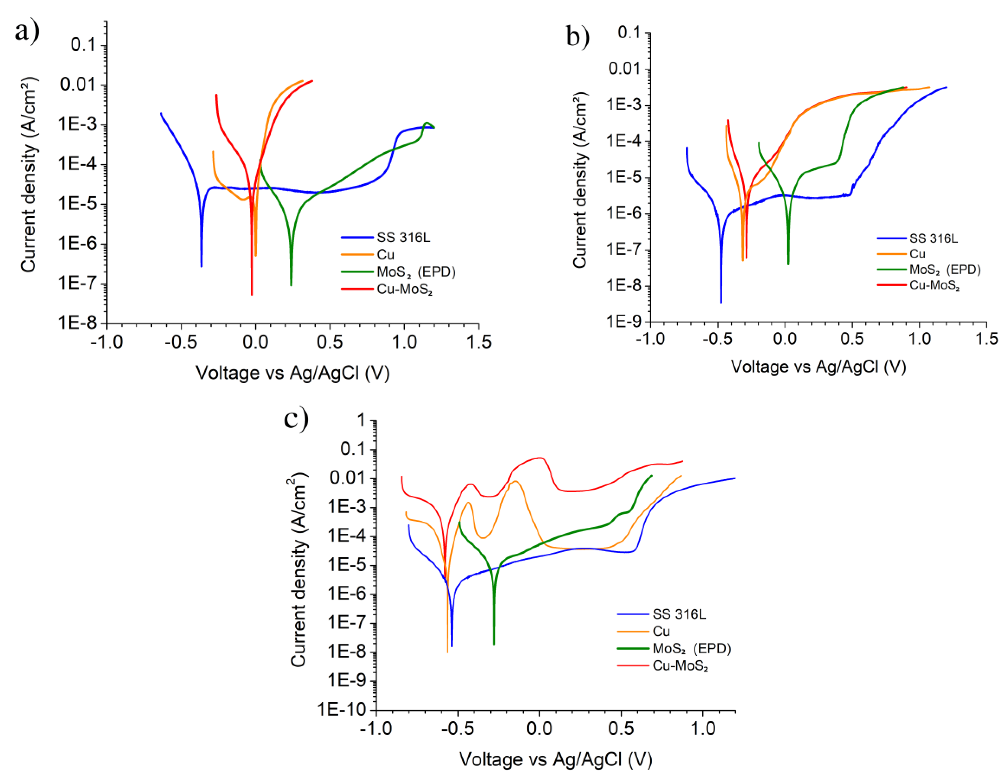
| Sample | Solution | OCP (mV) | Ecorr (mV) | icorr (uA/cm²) | βa (mV/dec) | βc (mV/dec) |
|---|---|---|---|---|---|---|
| SS 316L | 0.1 M H2SO4 | −247 | −302 | 4.4 | −12,100 * | −93 |
| Cu | 151 | 21 | 15.2 | 55 | 1230 * | |
| MoS2 (EPD) | 327 | 237 | 2.9 | 162 | −134 | |
| Cu–MoS2 | 371 | −9 | 35.5 | 83 | −150 | |
| SS 316L | 0.1 M NaCl | −419 | −468 | 2.6 | 345 | −124 |
| Cu | −128 | −319 | 13.2 | 333 | −99 | |
| MoS2 (EPD) | 141 | 33 | 11.9 | 148 | −188 | |
| Cu–MoS2 | −122 | −287 | 18.7 | 182 | −92 | |
| SS 316L | 0.1 M NaOH | −523 | −543 | 1.7 | 294 | −123 |
| Cu | −519 | −559 | 17.1 | 53 | −91 | |
| MoS2 (EPD) | −192 | −289 | 8.3 | 289 | −138 | |
| Cu–MoS2 | −544 | −561 | 296.7 | 77 | −165 |
© 2020 by the authors. Licensee MDPI, Basel, Switzerland. This article is an open access article distributed under the terms and conditions of the Creative Commons Attribution (CC BY) license (http://creativecommons.org/licenses/by/4.0/).
Share and Cite
Prado, L.H.; Virtanen, S. Cu–MoS2 Superhydrophobic Coating by Composite Electrodeposition. Coatings 2020, 10, 238. https://doi.org/10.3390/coatings10030238
Prado LH, Virtanen S. Cu–MoS2 Superhydrophobic Coating by Composite Electrodeposition. Coatings. 2020; 10(3):238. https://doi.org/10.3390/coatings10030238
Chicago/Turabian StylePrado, Lucia Helena, and Sannakaisa Virtanen. 2020. "Cu–MoS2 Superhydrophobic Coating by Composite Electrodeposition" Coatings 10, no. 3: 238. https://doi.org/10.3390/coatings10030238
APA StylePrado, L. H., & Virtanen, S. (2020). Cu–MoS2 Superhydrophobic Coating by Composite Electrodeposition. Coatings, 10(3), 238. https://doi.org/10.3390/coatings10030238