1. Introduction
Platinum is an interesting material used as a catalyst [
1,
2,
3,
4] for fuel cell electrodes [
3,
4,
5] and a protective layer against industrial corrosive atmosphere [
2] or sensors [
1,
6]. However, this material is very expensive, and its use as thin film is susceptible to minimizing the quantity used. One powerful technique to avoid its waste is DC magnetron sputtering. Kawamura et al. [
7] showed that platinum grows with a Volmer–Weber mode. In order to obtain a continuous film, the minimal thickness is around 0.4 nm. However, some problems appear when pure platinum is used, such as pollution by CO during the catalysis process [
8], or microstructure coarsening with the temperature that promotes pinholes or discontinuous films [
9,
10]. Many studies have focused on stabilizing continuous platinum coating with the temperature, and one solution is to deposit metallic platinum alloys (Pt–X): Pt–Ni [
11,
12], Pt–Ru [
8], Pt–Ir [
13,
14], and Pt–Ti [
15,
16,
17,
18,
19]. Among the solutions available in the literature, the Pt–Ti system presents some interesting properties, such as high thermal stability, very good behavior as a catalyst, and high resistance against corrosion due to the negative value of the formation enthalpy of the Pt–Ti bonds [
15]. The phase diagram of Pt–Ti alloys firstly presented by Murray [
20] was supported by many publications, and some minor corrections have been proposed on this system so far [
21].
In this paper, we deposited Pt–Ti metallic thin films through pulsed DC magnetron sputtering with various titanium concentrations. The chemical and morphological features were assessed via scanning electron microscopy equipped with energy dispersive X-Ray spectroscopy. The structural evolution was characterized by X-ray diffraction, and the electrical properties were determined by the four-point probe technique as a function of the temperature under static air and under reducing atmosphere (Ar with 10% of H2). Firstly, we deposited a thin coating within a large panel of titanium contents (0 to 47 at.%). Then, an intermetallic coating Pt3Ti with different thicknesses was synthesized (10 to 100 nm). The aim of this study is to propose the minimum thickness of Pt3Ti intermetallic layer required to be used as a current collector (for example in fuel cells) at high temperatures.
2. Experimental Details
Coatings have been deposited by co-sputtering of metallic targets in pure argon atmosphere. Pulsed DC supplies power the platinum (Pt, purity 99.95%) and titanium (Ti, purity 99.5%) targets mounted on balanced magnetrons—respectively, an Advanced Energy Pinacle+ pulsed at a fix frequency of 100 kHz for the Pt and 150 kHz for the Ti target. The reactor was a 90-litre cylinder pumped down with a turbo molecular pumping system allowing a base vacuum of less than 10
−4 Pa before refilling with argon at a convenient pressure. The argon flow rate introduced in the deposition chamber was controlled by a Brooks flowmeter, and the total pressure was measured using an MKS Baratron Gauge (model 690A01TRC, MKS Instrument France SA, Munchen, Germany) [
22].
The targets, 50 mm in diameter and 3 mm in thickness, are parallel to the substrate-holder and are spaced 120 mm from each other. Their distance from the substrate holder (D
T-S) was fixed at 60 mm. Different substrates, such as glass slides and dense alumina pellets (Keral 99, diameter = 16 mm, thickness = 0.63 mm), produced by Kerafol Gmbh (Eschenbach in der Operpfalz, Germany), were positioned at a distance around 55 mm from the axis of the rotating substrate-holder. Alumina substrates were used to carry out the heat treatments as well as the structural, microstructural, and electrical characterizations of the films. Glass slides were used to measure thickness through tactile profiling in addition to the thickness obtained by SEM. During the deposition stage, the different substrates were regularly rotated (20 Round Per Minute). The Pt discharge current was fixed at 0.2 A for all experiments, and the discharge current applied to the Ti target was varied from 0 to 1 A in order to obtain Pt–Ti coatings with different Ti contents. The main sputtering parameters are summarized in
Table 1.
The structural features of the coatings were determined through X-ray diffraction in a grazing incidence geometry using an incidence angle of 4 degrees configuration. A BRUKER D8 (Karlsruhe, Germany) focus diffractometer (Co Kα1+α2 radiations, λ = 0.178897 nm) equipped with a LynxEye linear detector (Bruker, Karlsruhe, Germany) with a fix incidence of 4° was used. Diffractograms were collected under air flow for 10 min in the [20°–80°] scattering angle range by steps of 0.019°. The morphology of the coatings was characterized via scanning electron microscopy (FEG SEM) using a JEOL JSM 7800F (Croissy sur Seine, France) equipped with energy-dispersive X-ray spectroscopy (EDS, XFlash 6|30, Bruker nano, Berlin, Germany) for chemical measurements. Resistivity measurements were first made at room temperature by means of a certified Jandel device (Multi height probe, Jandel Engineering Limited, Lindslade, UK), which allows the determination of the form factor of the measured cell temperature. Then, the electrical resistivity measurements as a function of temperature were taken with an HP 3458A multimeter (Agilent, Massy, France) on the Pt–Ti film deposited on alumina substrates. The four-point probe technique with four Pt aligned electrodes was employed. The two outer probes are the current-carrying electrodes (I1, I2), and the two inner ones were used to measure the voltage (E1, E2). The cell was placed inside an alumina tube and positioned in a Pekly furnace. The resistivities of the films were recorded from room temperature up to 1273 K with temperature steps and stabilization times of about 25 K and 20 min, respectively. Measurements were taken under static air and under reducing atmosphere (total flow rate was 60 sccm, and the gas was composed by Ar with 10% of H2).
3. Results and Discussion
3.1. Influence of Ti Content
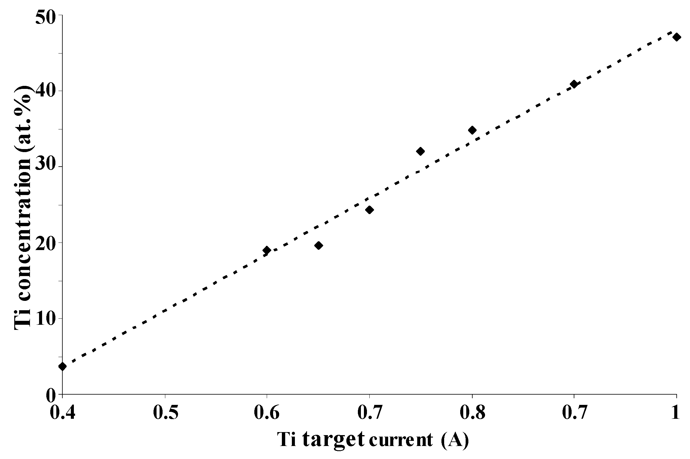
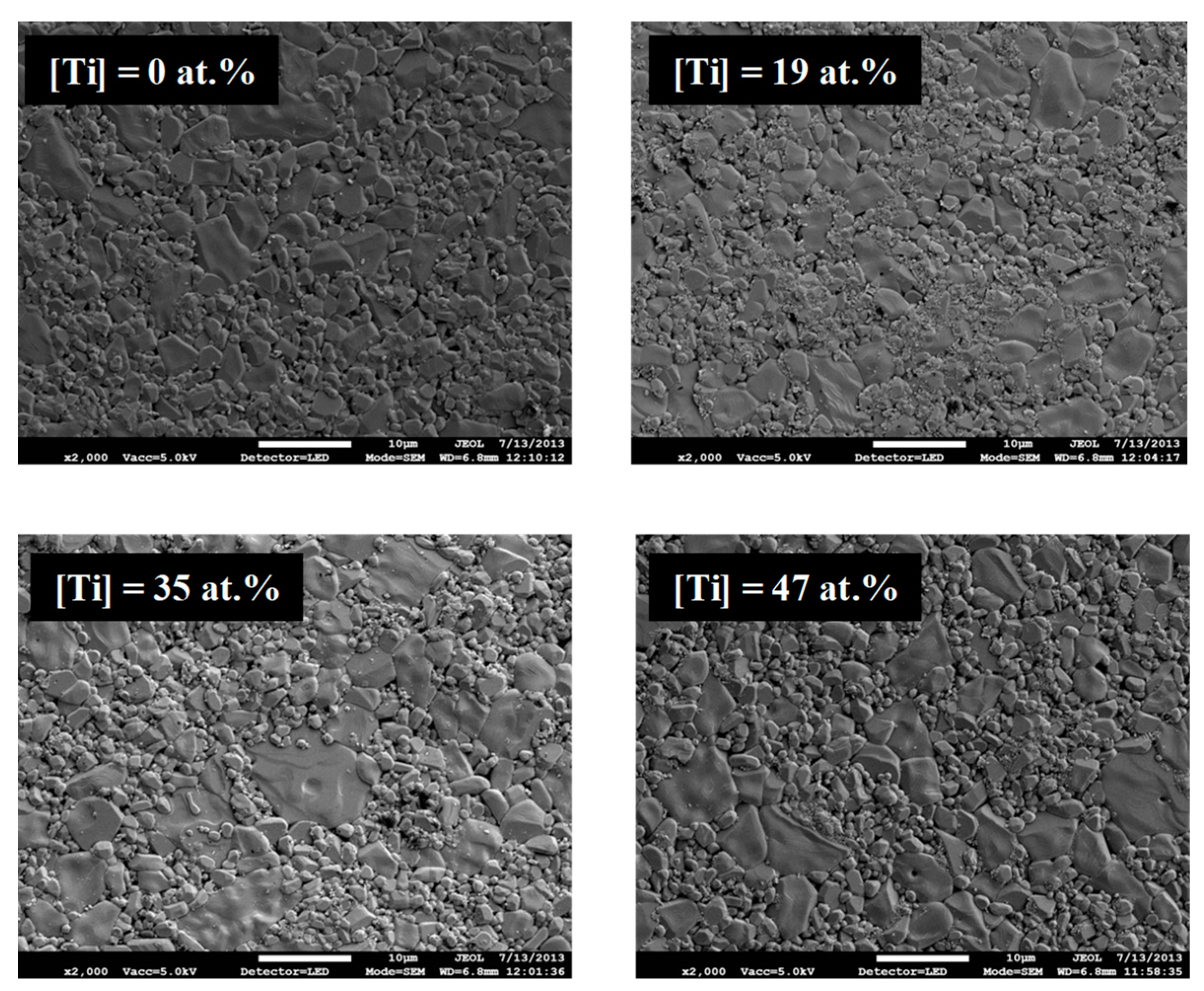
Figure 1 shows the titanium content in the coating as a function of the current applied to the titanium target. The linear evolution was assumed to proceed from the metallic flux increasing quite linearly with the discharge current on the Ti target in neutral atmosphere. Regardless of the film composition, as-deposited Pt–Ti metallic films perfectly cover the surface of alumina substrates. The micrographs obtained via SEM of the film top-view (
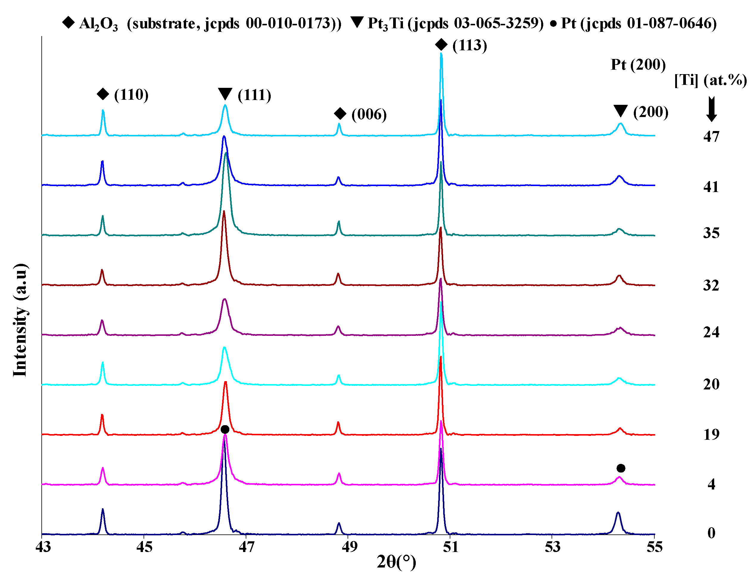
Figure 2) show that all the samples perfectly reproduce the substrate surface topography. Only the coatings of pure platinum and with 4 at.% titanium are crystallized in the face-centered cubic structure of platinum. All other films with higher Ti content present an amorphous structure. XRD patterns obtained after two hours of thermal oxidation at 1173 K in air of the Pt–Ti metallic films are shown in
Figure 3. All coatings are crystallized under the fcc structure according to the pure platinum structure. In comparison with the cubic cell of bulk platinum, the cell is more and more deformed with each increase in titanium content. The atomic radii are 0.139 and 0.147 nm for the platinum and titanium, respectively. Basically, the substitution of Pt atoms by titanium increases the lattice constant (i.e., the Bragg angle corresponding to (111) planes of platinum moves to smaller values while increasing the titanium content in the coating).
Figure 3 shows a reverse behavior for titanium concentration range from 4 at.% to 25 at.%. Spencer [
17] explained this phenomenon through the attractive bond length between platinum and titanium, which implies that the Pt–Ti bond is shorter than the Pt–Pt bond. Irrespective of the Ti content, the coatings remain a supersaturated fcc solid solution after annealing treatment at 1173 K. The intermetallic phases Pt
3Ti, Pt
5Ti
3, and PtTi of the Pt–Ti system predicted by Biggs et al. [
21] do not appear in these coatings.
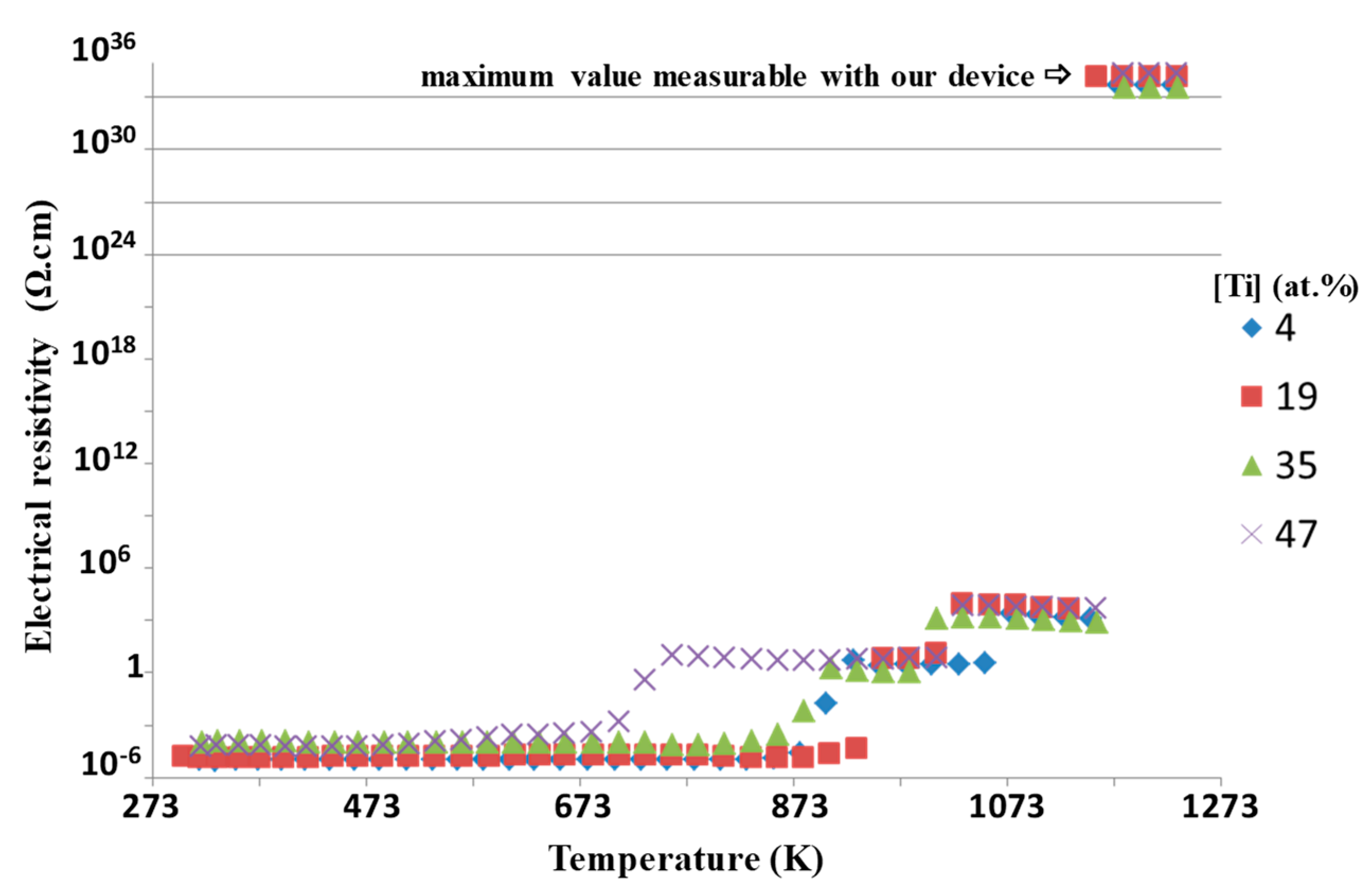
Figure 4 represents the resistivity of around 15 nm thick platinum-based coating of different Ti contents as a function of annealing temperature. The resistivity is quite constant when the temperature is lower than 673 K. As the temperature rises, the film resistivity increases as well [
9,
10]. The transition temperature from conductor to insulator is a function of the titanium content.
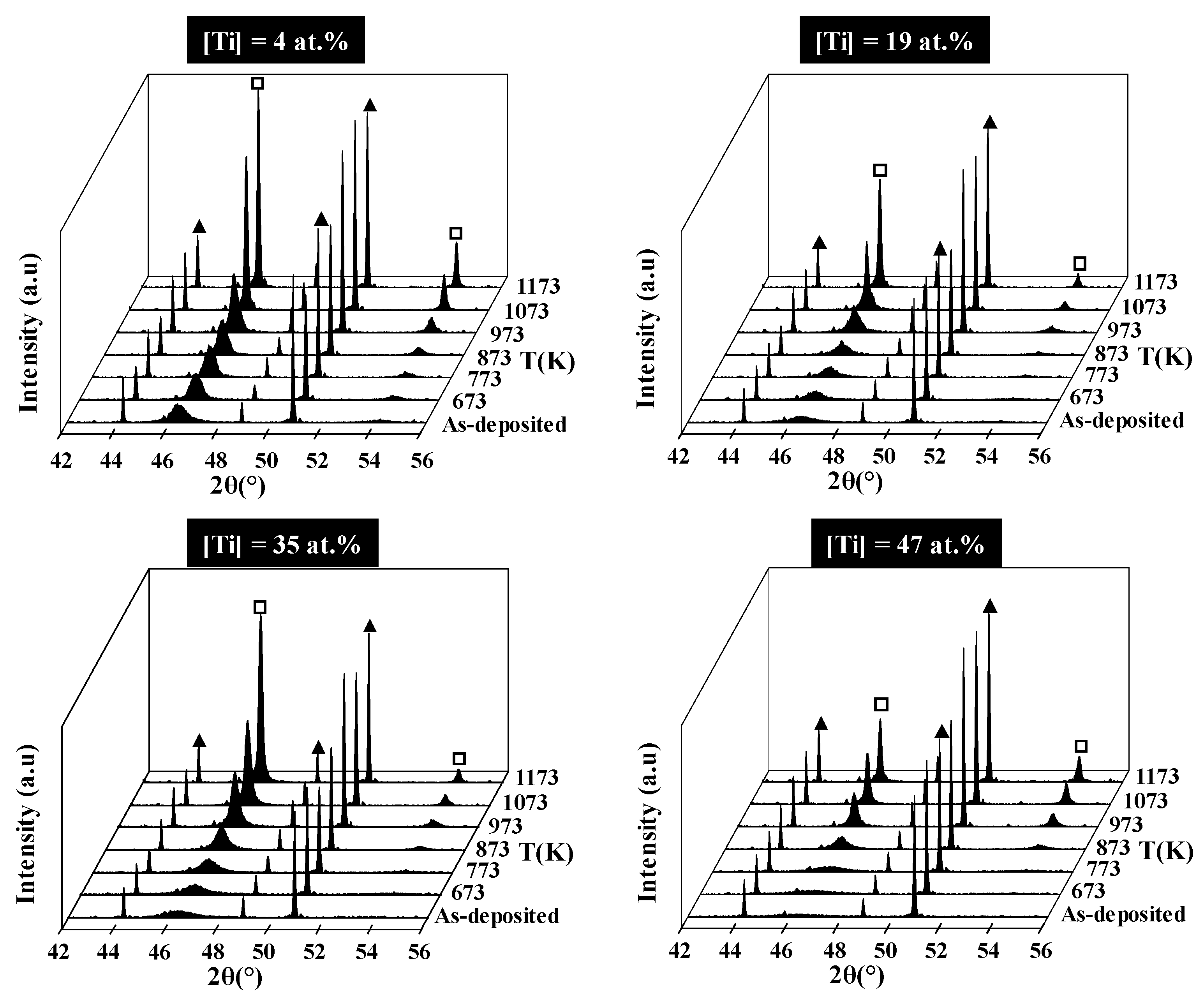
Figure 5 shows the XRD patterns of four coatings with different titanium concentrations as a function of the annealing temperature. The temperature at which the films start to crystallize depends on the Ti concentration. It extends over a range from 673 to 873 K, respectively, for pure Pt and Pt with 47 at.% of Ti. In the case of pure Pt and Pt with 4 at.% of Ti, the films are crystallized, roughly worked up, under the face-centered cubic structure. For films containing from 19 at.% to 47 at.% of Ti, crystallization begins from 873 K. Some jumps on the electrical resistivity value are observed (
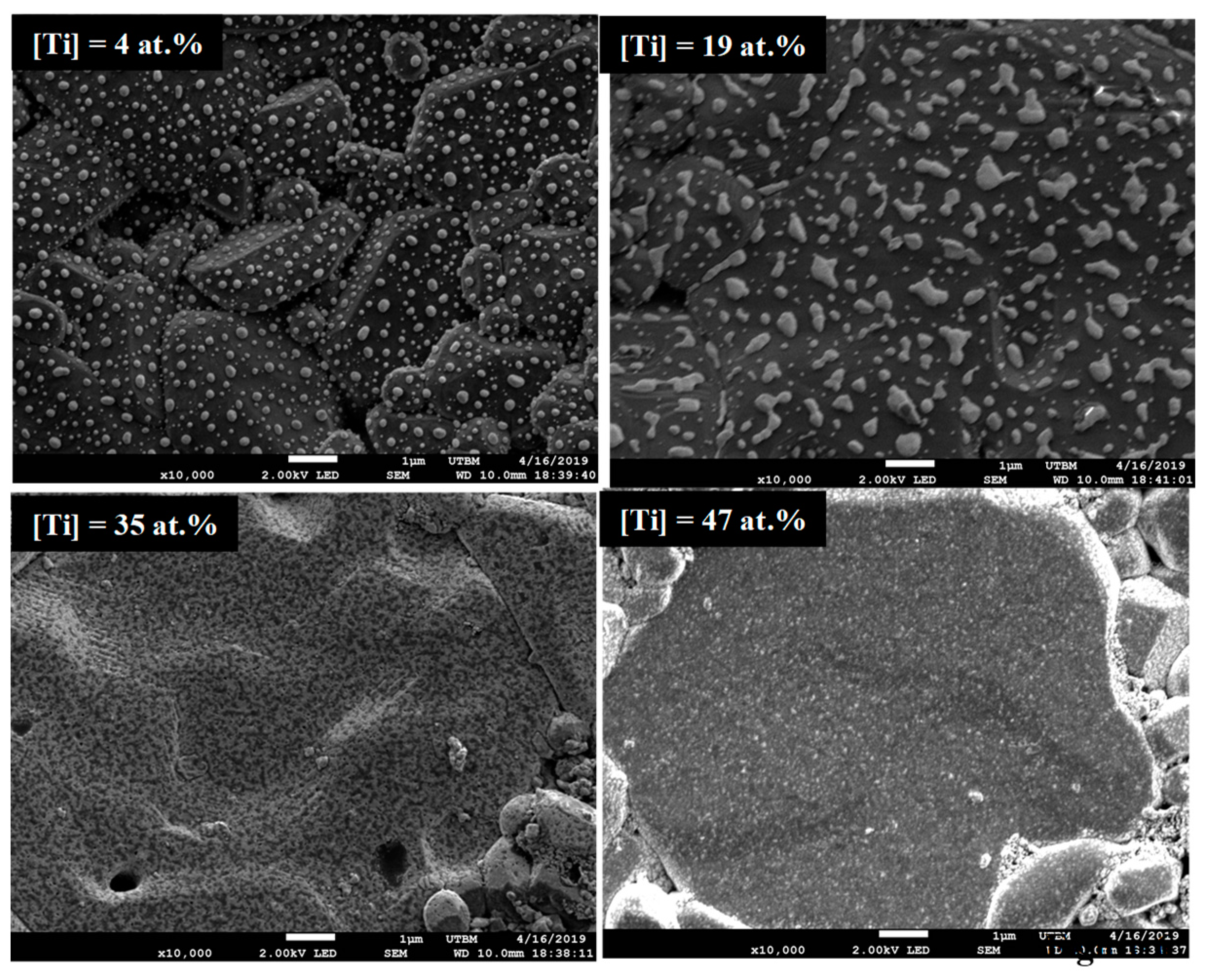
Figure 4). The temperature of these jumps is expected to correspond to the morphological evolution of the coatings. Indeed, SEM observation performed after electrical measurements up to 1273 K clearly shows the discontinuity of the films with the lower Ti contents that consist in isolated islands of submicronic size. For higher Ti contents, the film morphology appears granular, and although it seems to still percolate, the high resistivity is assumed to proceed from a strong refinement of the layer between the grains.
It is worth noting that the continuity of platinum coating with the temperature is very important to use this material as a current collector for fuel cell applications.
Figure 6 shows the top-view observation via SEM of the films after electrical measurements performed at 1273 K for coatings with four different concentrations of titanium (4 at.%, 19 at.%, 35 at.%, 47 at.%). When the temperature is higher than 873 K, the coatings containing up to 19 at.% Ti are not continuous and are composed by small islands a few nanometers of platinum on the alumina surface [
9,
10,
23]. This surface morphology is attributed to the Ostwald ripening mechanism during the sintering of the film with the annealing treatment during the electrical measurement [
10]. The coating containing 35 at.% Ti also presents less covering of the alumina substrate, but it still percolates, thus maintaining a measurable resistivity. Finally, the coating containing 47 at.% Ti remains continuous.
3.2. Influence of the Thickness of Pt3Ti Coatings
The convenient composition of Pt
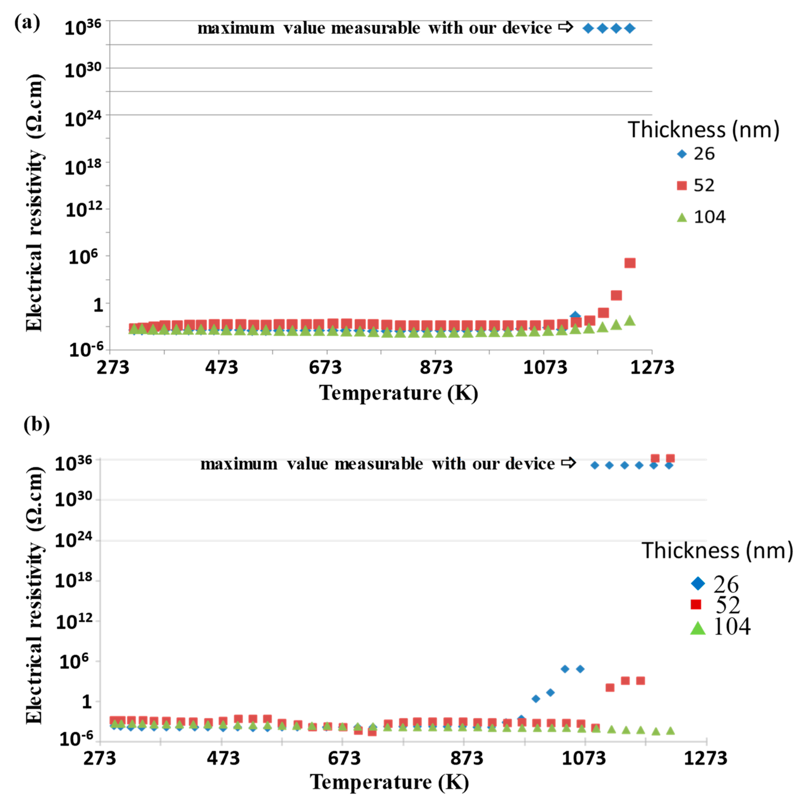
3Ti is obtained if the discharge currents are 0.2 A pulsed at 100 kHz on the Pt target and 0.7 A pulsed at 150 kHz on the Ti target. The coatings were deposited under 0.5 Pa argon pressure, and the sputtering time was adjusted to synthesize the films with different thicknesses (26, 52, and 104 nm). The thinner film annealed under air presents an insulating behavior over about 1173 K, while thicker films continue to conduct up to about 1273 K (
Figure 7a). When the annealing has been realized under reducing atmosphere, an insulating behavior is observed over about 1100 K for the 26 nm thick film and over about 1200 K for the 52 nm thick one. The thickest film behaves as a conductor for up to at least 1273 K (
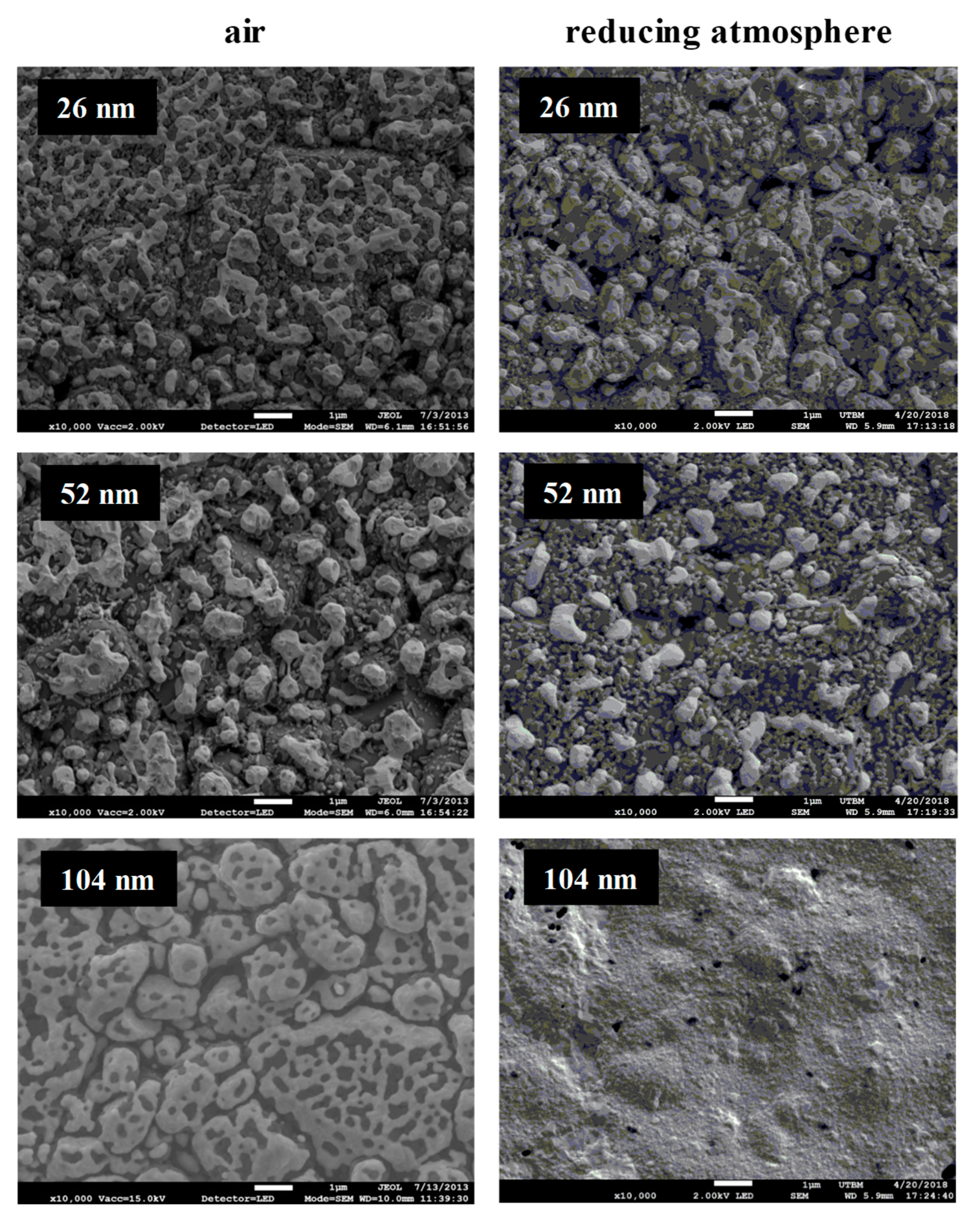
Figure 7b). In all atmospheres, the resistivity decreases with increasing the film thickness and remains stable up to at least 1273 K for the highest thickness (≈ 104 nm). This behavior is consistent with the SEM observation (top-view in
Figure 8), where the thinnest film consists in separated islands, whereas the thicker one still percolates under air and remains quite continuous under reducing atmosphere. The benefit effect of titanium addition against grain coarsening and the Ostwald ripening mechanism is less important when the thickness increases. A minimum of 50 and 100 nm thickness is necessary to obtain a stable current collector at high temperature application and avoid some island formation under air or under reducing atmosphere.
4. Conclusions
Platinum–titanium is a potential material as a current collector in the fuel cell applications. Pt–Ti thin films were elaborated via co-sputtering of two metallic Pt and Ti targets in pure Ar atmosphere. The titanium concentration of coating ranged as a function of intensity applied on the titanium target. All as-deposited coatings were perfectly covering and reproduced the substrate surface morphology of alumina pellets. X-ray diffraction results showed that the as-deposited metallic films with or without small addition of titanium are crystallized in the fcc platinum structure, while for Ti concentrations higher than 4 at.%, the coatings become amorphous. For the thinner coating (15 nm), the Ostwald ripening phenomenon was observed with the annealing treatment irrespective of the Ti concentration.
We also observed that if the Pt3Ti coating thickness is higher than 100 nm, the electrical and morphological properties as a function of the annealing treatment remain stable. This film could be a good potential candidate as a current collector at high temperature under oxidizing or reducing atmosphere.
Author Contributions
Conceptualization, M.A.-P.-Y., P.B. and A.B.; methodology, M.A.-P.-Y.; validation, A.B.; formal analysis, M.A.-P.-Y., P.B.; investigation, M.A.-P.-Y., P.B. and A.B.; resources, A.B.; data curation, M.A.-P.-Y., P.B.; writing—original draft preparation, P.B. and M.A.-P.-Y.; writing—review and editing, M.A.-P.-Y., P.B., N.M. and A.B.; supervision, A.B.; project administration, P.B. and A.B.; All authors have read and agreed to the published version of the manuscript.
Funding
The authors are indebted to the Pays de Montbéliard Agglomération (PMA) for its financial support.
Acknowledgments
This work was done within the FEMTO-ST SURFACE platform.
Conflicts of Interest
The authors declare no conflict of interest.
References
- Matsumiya, M.; Shin, W.; Izu, N.; Murayama, N. Nano-structured thin film Pt catalyst for thermoelectric hydrogen gas sensor. Sens. Actuators B 2003, 93, 309–315. [Google Scholar] [CrossRef]
- Gatel, C.; Snoeck, E. Comparative study of Pt, Au, and Ag growth on Fe3O4 (001) surface. Surf. Sci. 2006, 600, 2650–2662. [Google Scholar] [CrossRef]
- Alvisi, M.; Galtieri, G.; Giorgi, L.; Serra, E.E.; Signore, M.A. Sputter deposition of Pt nanoclusters and thin films on PEM fuel cell electrodes. Surf. Coat. Technol. 2005, 200, 1325–1329. [Google Scholar] [CrossRef]
- Enea, O.; McEvoy, A.J. Electrooxidation reactions on gas-diffusion electrodes catalyzed by DC sputtered Pt. Electrochim. Acta 1998, 44, 1441–1445. [Google Scholar] [CrossRef]
- Bierbele-Hütter, A.; Hertz, J.L.; Tuller, H.L. Fabrication and electrochemical characterization of planar Pt-CGO microstructures. Acta Mater. 2008, 56, 177–187. [Google Scholar] [CrossRef]
- Hotovy, I.; Huran, J.; Siciliano, P.; Capone, S.; Spiecs, L.; Rehacek, V. Enhancement of H2 sensing properties of NiO-based thin films with a Pt surface modification. Sens. Actuators B 2004, 103, 300–311. [Google Scholar] [CrossRef]
- Kawamura, M.; Mashima, T.; Abe, Y.; Sazaki, K. Formation of ultra-thin continuous Pt and Al films by RF sputtering. Thin Solid Films 2000, 377–378, 537–542. [Google Scholar] [CrossRef]
- Black, M.; Cooper, J.; Mc Ginn, P. Scanning electrochemical microscope characterization of thin film Pt–Ru alloys for fuel cell applications. Chem. Eng. Sci. 2004, 59, 4839–4845. [Google Scholar] [CrossRef]
- Sreemany, M.; Sen, S. Effect of substrate temperature and annealing temperature on the structural, electrical an microstructural properties of thin Pt films by rf magnetron sputtering. Appl. Surf. Sci. 2006, 253, 2739–2746. [Google Scholar] [CrossRef]
- Wang, X.; Huang, H.; Holme, T.; Tian, X.; Prinz, F.B. Thermal stabilities of nanoporous metallic electrodes at elevated temperatures. J. Power Sources 2008, 175, 75–81. [Google Scholar] [CrossRef]
- Amatatsu, Y.; Muhihara, K.; Shi, J.; Yang, J.; Hashimoto, M. Growth mode of Pt1-xNix films dc-sputter-deposited on MgO (001). Appl. Surf. Sci. 2001, 169–170, 401–404. [Google Scholar] [CrossRef]
- Xiong, L.; Manthiram, A. Effect of atomic ordering on the catalytic activity of carbon supported PtM (M = Fe, Co, Ni, and Cu) alloys for oxygen reduction in PEMFCs. J. Electrochem. Soc. 2005, 152, A697–A703. [Google Scholar] [CrossRef]
- Kuribayashi, K.; Fujita, Y.; Isige, H.; Iwanuma, T. Sputter deposited Pt–Ir oxides thin films and their characterization. Mater. Sci. Eng. B 2004, 109, 188–191. [Google Scholar] [CrossRef]
- Kamachi Mudali, U.; Raju, V.R.; Dayal, R.K. Preparation and characterisation of platinum and platinum-iridium coated titanium electrodes. J. Nucl. Mater. 2000, 277, 49–56. [Google Scholar] [CrossRef]
- Ding, E.; More, K.L.; He, T. Preparation and characterization of carbon-supported PtTi alloy electrocatalysts. J. Power Sources 2000, 175, 794–799. [Google Scholar] [CrossRef]
- Noolu, N.J.; Kerr, H.W.; Zhou, Y.; Xie, J. Laser weldability of Pt and Ti alloys. Mater. Sci. Eng. A 2005, 397, 8–15. [Google Scholar] [CrossRef]
- Spencer, M.S. Surface segregation in some non-ideal platinum alloys 1 Platinum-titanium alloys. Surf. Sci. 1984, 145, 145–152. [Google Scholar] [CrossRef]
- Li, M.; Han, W.; Li, C. Thermodynamic assessment of the Pt-Ti system. J. Alloy. Compd. 2008, 461, 189–194. [Google Scholar] [CrossRef]
- Abraham, F.F.; Tsai, N.H.; Bond, G.M. Bond and strain energy effects in surface segregation: An atomic calculation. Surf. Sci. 1979, 83, 406–422. [Google Scholar] [CrossRef]
- Murray, J.L. The Pt–Ti (Platinum–Titanium) system. Bull. Alloy Phase Diagr. 1982, 3, 329–334. [Google Scholar] [CrossRef]
- Biggs, T.; Cornish, L.A.; Witcomb, M.J.; Cortie, M.B. Revised phase diagram for the Pt–Ti system from 30 to 60 at.% platinum. J. Alloy. Compd. 2004, 375, 120–127. [Google Scholar] [CrossRef]
- Arab Pour Yazdi, M.; Briois, P.; Billard, A. Influence of the annealing conditions on the structure of BaCe1−xYxO3-α coatings elaborated by DC magnetron sputtering at room temperature. Mater. Chem. Phys. 2009, 117, 178–182. [Google Scholar] [CrossRef]
- Arab Pour Yazdi, M. Synthèse par pulvérisation cathodique et caractérisation d’électrolytes conducteurs protoniques pour les piles à combustible de type PCFC. Ph.D. Thesis, Université de Belfort-Montbéliard, Sevenans, France, 2009. [Google Scholar]
© 2020 by the authors. Licensee MDPI, Basel, Switzerland. This article is an open access article distributed under the terms and conditions of the Creative Commons Attribution (CC BY) license (http://creativecommons.org/licenses/by/4.0/).
