Article

Cold Gas Spraying of a High-Entropy CrFeNiMn Equiatomic Alloy

1
Department of Chemistry and Materials Science, Aalto University, Kemistintie 1, 02150 Espoo, Finland
2
Materials Science and Environmental Engineering, Faculty of Engineering and Natural Sciences, Tampere University, Korkeakoulunkatu 6, 33720 Tampere, Finland
*
Author to whom correspondence should be addressed.
Coatings 2020, 10(1), 53; https://doi.org/10.3390/coatings10010053
Submission received: 30 November 2019 / Revised: 29 December 2019 / Accepted: 2 January 2020 / Published: 8 January 2020
(This article belongs to the Special Issue Cold Spraying: Recent Trends and Future Views)

Abstract

:
Cold gas spraying was used to make a coating from an equiatomic CrFeNiMn high-entropy alloy. This four-component alloy was chosen because it is Co-free, thus allowing application in nuclear industries as a possible replacement of currently used stainless steel coatings. The feedstock material was gas atomized powder with a particle size distribution from 20 to 45 µm. A number of parameters were tested, such as the powder feed rate and gas feed pressure, in order to obtain as dense a coating as possible with nitrogen as the process gas. Spraying was performed using a gas preheating temperature of 1000 °C, gas feed pressure ranging from 50 to 60 bar, and two powder feeding rates. The coating thicknesses ranging from 230 to 490 µm and porosities ranging from 3% to 10% were obtained depending on the powder feed rate and gas feed pressure. The hardness of the cross-section of the coating was usually lower than that of the surface. The highest coating hardness obtained was above 300 HV0.3 for both the surface and the cross-section. The as-atomized powder consisted of a face-centered cubic (FCC) phase with a minute amount of body-centered cubic (BCC) phase, which was no longer detectable in the coatings. The microstructure of the coating was highly stressed due to the high degree of deformation occurring in cold gas spraying. The deformation leads to strain hardening and induces a pronounced texture in the coating. The {111} planes tend to align along the coating surface, with deformation and texturing concentrating mainly on particle boundaries. A high-entropy alloy (HEA) coating was successfully sprayed for the first time using nitrogen as a process gas. The coating has the potential to replace stainless steel coatings in nuclear industry applications.

1. Introduction

High-entropy alloys (HEA) were first proposed by Yeh et al. [1] in 2004 as a multicomponent alloy consisting of equal amount of each element. The first discovered HEA was CoCrFeNiMn by Cantor et al. [2]. Even with the presence of multiple elements in equiatomic concentrations, most HEAs have a simple cubic single phase microstructure [3]. Shortly afterwards, many interesting properties including high strength, high ductility, the sluggish diffusion of alloying atoms, and radiation resistance among others were found in these alloys [4]. Since the first discovery, multiple HEA systems have been studied, but CoCrFeNiMn, also known as the Cantor alloy, remains the most studied. Wu et al. [5] studied a family of face-centered cubic (FCC) alloys based on CoCrFeNiMn HEA. They determined the phase composition and microstructure of all the related quaternary, ternary, and binary systems, and found that the drop cast and homogenized quaternary CrFeNiMn has a multi-phase structure consisting of FCC and body-centered cubic (BCC) phases, with a small amount of the latter. However, in the Cantor alloy, the presence of Co make it less suitable for use in nuclear industry, due to the possible activation to 60Co in the presence of neutrons. Therefore, Co-free CrFeNiMn has also stirred up interest as a candidate for irradiation resistant material [4,5,6,7].
Stepanov et al. [8] made a series of multicomponent Co-free alloys with a composition of Fe40Mn28Ni32−xCrx (where x was 4, 12, 18, or 24). The alloys consisted of a single FCC phase except for the composition of Fe40Mn28Ni8Cr24, which had a tetragonal phase present. They obtained a tensile yield strength of 210 MPa for the lowest Cr content (x = 4) and 310 MPa for the highest chromium content (x = 24). A near equiatomic FeNiMnCr18 was made by Wu et al. [4] with a tensile strength ranging from 300 to 900 MPa tested at 77–873 K with the highest strength obtained at 77 K. This increase in strength at low temperatures is attributed to the twins observed in the tensile fractures. Kumar et al. [6] found an increased radiation resistance for FeNiMnCr18 when comparing to traditional Fe–Cr–Ni-based stainless steels. When the CrFeNiMn alloy is produced by gas atomization, the powder phase composition depends on the cooling rate [9]. The content of BCC phase in the alloy increased with increasing cooling speed; thus, the more BCC phase the powder contains, the smaller the powder particle size.
Cold gas spraying (CGS) is a solid-state coating method, i.e., no melting occurs during the coating formation. CGS was developed in the 1980s [10] and patented in 1994 [11]. In high pressure CGS, inert gas (typically nitrogen or helium) is heated to a temperature of up to 1100 °C with a maximum pressure of 70 bar. In low pressure CGS, inert gas or compressed air can be used. The inert carrier gas flow takes the powder into the spray nozzle, where it is combined with the heated gas and accelerated out the nozzle with a high velocity toward a substrate, where a coating is formed. CGS differs from the traditional spray-coating methods by not relying on melting to adhere to the substrate; cold spraying also has lower temperature and higher velocity compared to other thermal spray processes [12]. Instead, it utilizes the kinetic energy of the particles to form the coating and metallurgical bonding [13]. The benefits of the lower process temperatures during CGS results in a coating that is oxidation free, has less thermal stresses, and inherits the chemical and phase composition of the original microstructure [10,14,15,16,17]. Coating formation based on plastic deformation via high velocity, and thus the coating material or part of it needs to be plastically deformable. Cold gas spraying typically used for metals, e.g., Cu, Ta [18], Ni [19,20], and Cr [21] as well as metal alloys e.g., Ni–Cr [20], Ni–Cu [19,20], Co-based [22], and Fe-based [23] materials. In addition to this, cold spray process development has gone toward higher process temperatures and pressures enabling use on high-performance materials e.g., Ni-based superalloys [24,25], stainless steels [26], and hard metals, as coating feedstock materials [27]. Couto et al. [28] compared WC–Co coatings created using CGS and high-velocity oxygen fuel (HVOF) and found that the coatings created by CGS did not contain brittle dissolution phases typical of HVOF coatings and consequently displayed better wear resistance than the HVOF coatings.
Cold gas spraying (CGS) has been studied very little on HEAs, but other thermal spraying techniques, more specifically plasma spraying [29,30,31,32] and HVOF [32], have been investigated more thoroughly. Yue et al. [29] laser remelted a plasma sprayed AlCoCrCuFeNi coating to remove the residual microporosity after the coating. Löbel et al. [30] made a comparison of the mechanical properties between milled and gas atomized powder in the use of atmospheric plasma spraying (APS) and found that the atomized powder had superior wear and mechanical properties. Ang et al. [31], in turn, created AlCoCrFeNi and MnCoCrFeNi coatings using plasma spraying and found that they exhibited higher hardness when compared to a plasma sprayed NiCrAlCoY bond coat. Hsu et al. [32] used HVOF and APS to create Ni0.2Co0.6Fe0.2CrSi0.2AlTi0.2 coatings, which had similar mechanical properties, with the notable differences being in porosity and oxide content. The APS coating had a higher porosity of 4.3% when compared to 2.8% of the HVOF coating, and the oxide content of APS was 5.82%, while HVOF resulted in 2.86%.
A FeCoNiCrMn alloy has been coated with cold spraying using helium as the process gas by Yin et al. [33]. They found that the coating retained its original phase structure as well as an improvement in hardness due to grain refinement. The cold-sprayed coating also showed a lower wear rate in comparison to laser-cladded coatings.
In this paper, we focus on the cold gas spraying of Co-free equiatomic Cr–Fe–Ni–Mn high-entropy alloy powder using nitrogen as the process gas and on the obtained properties of the coatings. The feedstock material was gas atomized powder, with a size range from 20 to 45 µm and characterized earlier by us [9]. A number of parameters were tested, such as powder feed rate and gas feed pressure, in order to obtain as dense a coating with nitrogen as the process gas. The deformation of the formed coatings was studied by electron backscattered diffraction (EBSD) inverse pole figure (IPF) mapping, XRD texture measurements, and flattening of the powder particles. The mechanical properties of the coatings were evaluated by hardness measurements.

2. Materials and Methods

The powder used for experiments was gas atomized at Bremen University (Bremen, Germany). Details of powder production and properties are given in [9]. The gas atomized powder was spherical in nature and well-suited for cold spraying. The typical powder particle distributions used in cold spraying are between 5 and 50 µm [18]. A powder size distribution of 20–45 µm was chosen for the cold spray process.
Cold spraying was performed at Tampere University (Tampere, Finland) using PCS-100 cold spray equipment (PlasmaGiken Co., Ltd., Osato, Saitama, Japan).
Powder was fed to the spray gun with the carrier gas and mixed there with a high-pressurized and preheated process gas. A powder-gas mixture was forced through the de Laval nozzle, where the high velocity of the particles was achieved. Particles hit the substrate, deforming and building up the coating at the spraying distance of 40 mm. Gas pressure, gas temperature, and the powder feed rate were the varied spray parameters. The nozzle was water-cooled to avoid the nozzle clogging. Nitrogen was used as the carrier gas to coat a Fe52 steel substrate having a size of 50 mm × 50 mm. The substrate was grit blasted with Al2O3 grits (Mesh 24) prior to coating deposition. The gas pressure was varied from 50 to 60 bar, and the preheating temperature was selected as 1000 °C. Process parameters were chosen based on previous studies with stainless steels and preliminary experiments with HEAS powder and another CGS system. Two powder feed rates (1 and 2 rpm) were also used in order to see the influence of powder feeding rate to the coating formation and build up. A spray distance of 40 mm was used, with a step size of 1 mm and traverse speed of 10 m/min. Each coating consisted of two layers.
Powder feeding rates as g/min was not measured, but it is expected that 2 rpm provides twice the amount of powder in comparison to 1 rpm, as it has been experimentally measured with other powder with the same setup. The manufacturer has provided that powder feed rate 1 corresponds to 17 g/min and feed rate 2 corresponds to 34 g/min for 316 stainless steel powder. Powder feed rate 1 will be referred to as a lower powder feed rate and powder feed rate 2 will be referred to as a higher powder feed rate. Without exact powder feed rate amounts, the deposition efficiency (DE) can only be estimated without an exact value. However, there are several coating properties, such as thickness, porosity, and spray parameters such as powder feed rate and gas pressure, which give an indication of the relative DE of the coatings. The coating parameters are summarized in Table 1. Coated samples were cut into pieces. Part of the pieces were prepared on the coating surface by grinding (P2500), while others were prepared to obtain cross-sections of the coatings. The latter were cut out and hot mounted in Polyfast (Struers, Ballerup, Denmark) and then ground down using 1200 grit SiC-paper followed by mechanical polishing using 5 µm, 1 µm, and 300 nm colloidal alumina. The samples were finalized by vibratory polishing for 16 h using 40 nm colloidal silica.
X-ray diffraction (XRD) patterns were collected from the main coating surface after grinding using Panalytical Xpert Pro Powder (Almelo, The Netherlands) equipment and a Co anode. Coating texture was determined by Panalytical X’pert MRD (Almelo, The Netherlands), using a Cu anode.
Vickers hardness was measured with an Innovatest Nexus 4303 Vickers indenter (Maastricht, The Netherlands) on both polished cross-sections and polished coating surfaces. An average of seven measurements were taken on each sample using a load of 300 g. Scanning electron microscopy (SEM) was carried out using a Tescan Mira3 (Kohoutovice, Czech Republic) equipped with an energy-dispersive spectroscopy (EDS) detector Thermo Fischer Scientific (Waltham, MA, USA). The porosity of the coatings was determined from a minimum of 10 SEM backscattered electron (BSE) images and calculated using ImageJ free software. The degree of particle deformation was also measured from the SEM images using ImageJ. Particle deformation was calculated based on the change of powder shape from round spherical to a deformed elliptical by measuring the two main axes of the ellipse. First, the long axis of the particle was measured followed by the measurement of the short axis perpendicular to the long one in the middle of the axis. A minimum of 20 particles was measured on each coating. EBSD–IPF mapping was made using an Oxford Instruments, Channel 5, EBSD system (Abingdon, UK) attached to a Zeiss Ultra 55 FEG-SEM (Oberkochen, Germany). EBSD maps were taken from cross-section samples to study the microstructure of the coatings. High-resolution scanning electron microscopy (HR-SEM) imaging was performed using a JEOL JIB-4700F (Akishima, Tokyo, Japan).
Nanoindentation was measured with Hysitron TI 950 (Minneapolis, MN, USA) using a diamond Berkovich tip. The maximum load used was 1000 µN, with a loading time of 5 s, holding time of 2 s, and an unloading time of 5 s. The elastic modulus was calculated assuming a Young’s modulus of 1140 GPa and a Poisson ratio of 0.07 for the diamond tip. The Poisson ratio of the equiatomic CrFeNiMn alloy was taken as 0.27 [9].

3. Results and Discussion

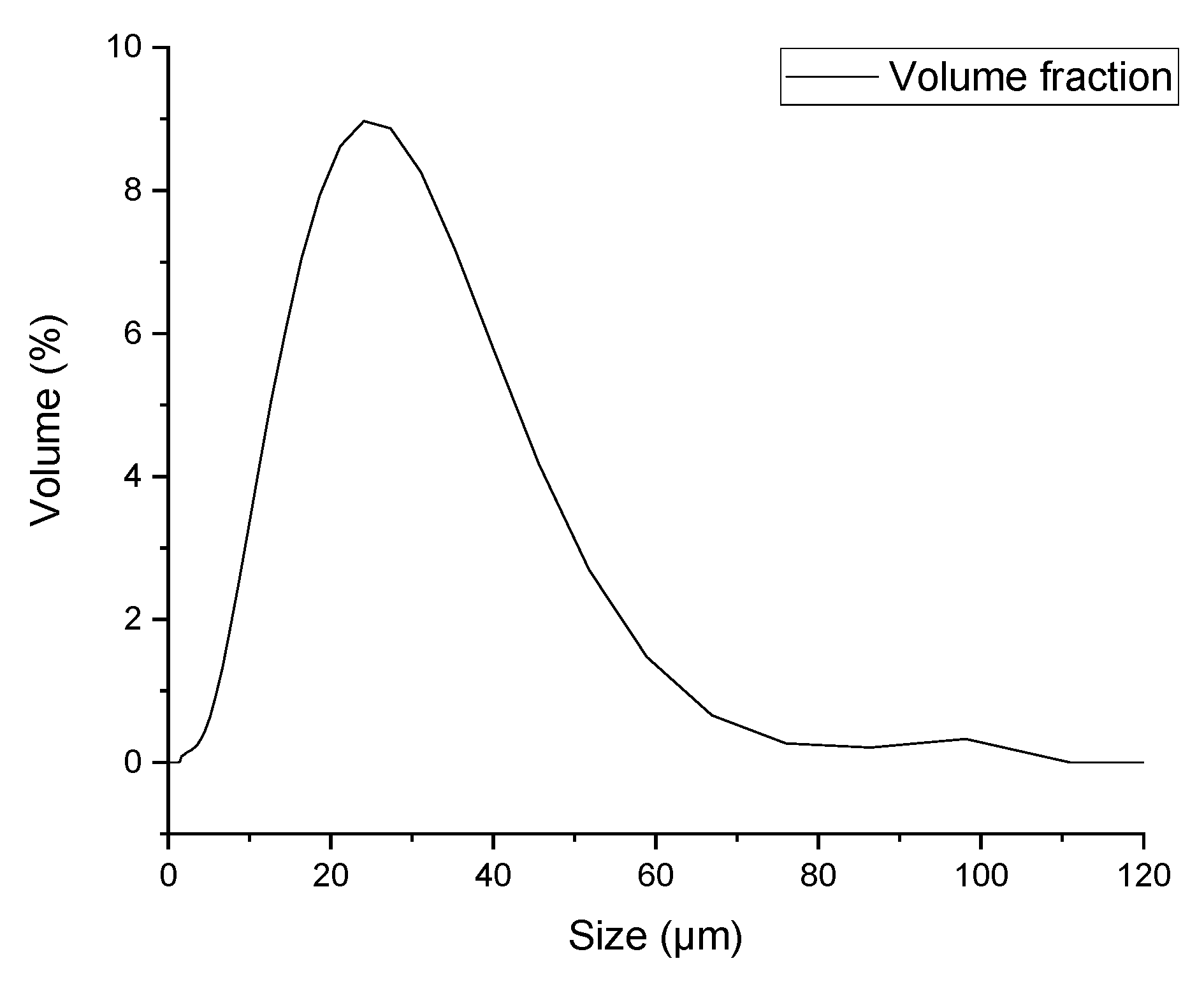
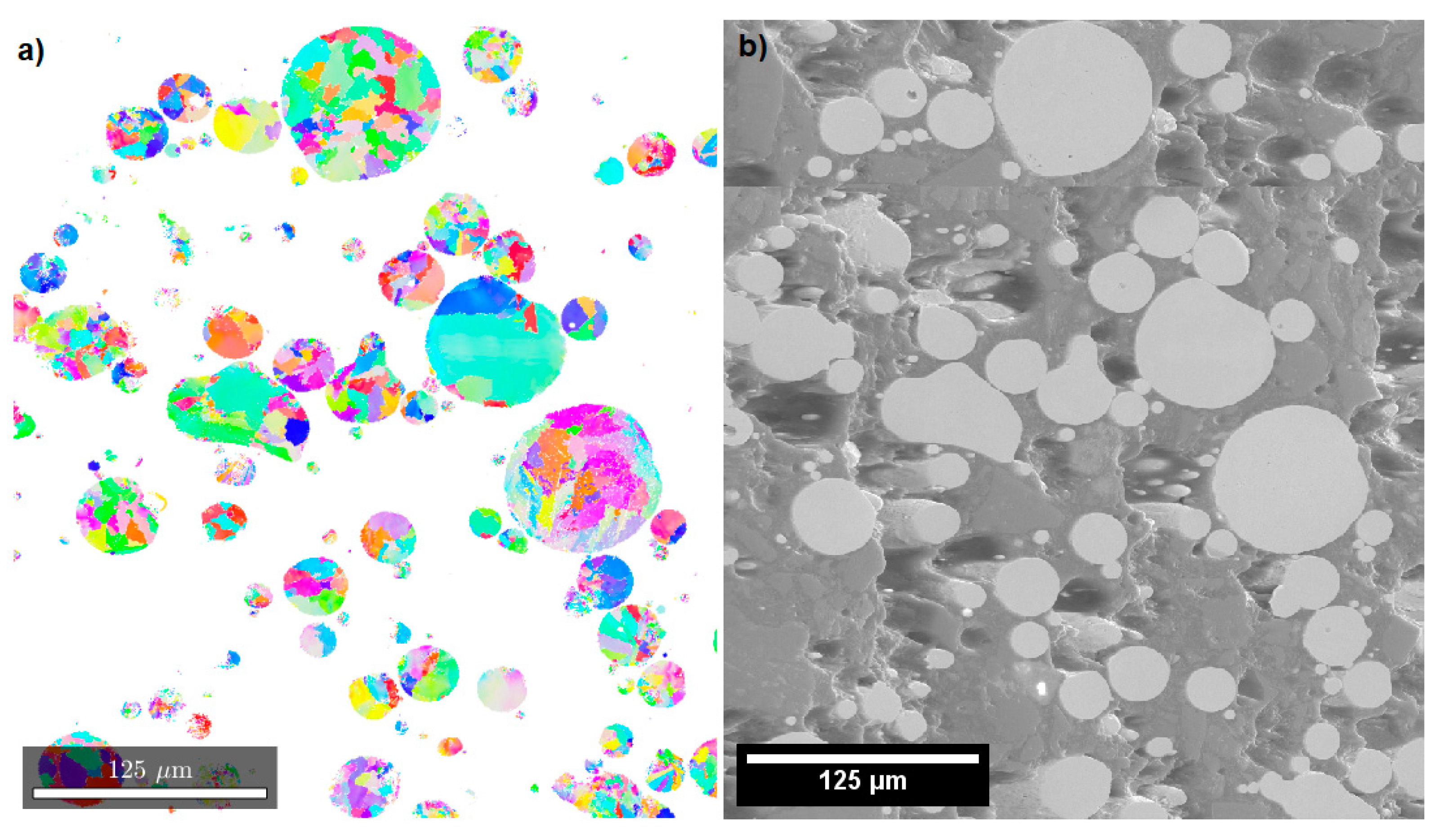
3.1. Powder Characterization

Figure 1 shows the particle size measurement for the powder sieved to 20–45 μm. The powder has a d10 value of 9 µm, a d50 value of 20.8 µm, and a d90 value of 39.9 µm. There is a small amount of powder below 20 µm and above 45 µm. Figure 2a shows the electron backscattered diffraction (EBSD) image of the microstructure of the powder cross section prior to coating and Figure 2b shows the corresponding SEM secondary electron (SE) image. The powder has varying grain size, ranging from near particle-sized grains down to a few microns.

3.2. Coating Thickness, Density, and Porosity

Five coatings were successfully sprayed using nitrogen as the process gas. The obtained properties with their standard deviations are shown in Table 1. In CGS, the process parameters affect particle deformation, which in turn affects porosity level in the coating structure [34]. The obtained coating thicknesses range from 230 to 350 µm using the lower powder feed rate 1 and from 380 to 490 µm at a higher powder feed rate, the porosities range from 3% to 10% for powder feed rate 1 and from 6% to 9% for a higher powder feed rate. The higher powder feed rate results in twice the thickness of the lower powder feed rate, yielding at 55 bar a very similar DE when the powder feed rate is doubled. However, at 60 bar, the coating thicknesses are very similar, i.e., 350 and 370 µm, with a higher powder feed rate only having ≈10% higher thickness, resulting in a significantly lower DE. The 60 bar feed pressure with the lower powder feed rate did result in a thicker coating than with 50 and 55 bar, also indicating higher DE values. An increase in DE using a larger feed pressure has also been noticed by [26]. The coating made with a lower powder feed rate and 55 bar pressure has a lower DE when compared with the coating made at 50 bar, which was determined based on the thickness of the coatings. Porosity is the lowest with the highest feed pressure used, also indicating an increased DE of the parameters [26]. Deposition efficiency is not only dependent on coating thickness; however, without the information of exact powder amounts going through, the system density and thickness are the only parameters to estimate the DE. The increased amount of powder at 60 bar does not create a coating due to the higher particle feed rate affecting the particle velocity by decreasing it. However, at the same time, the particle and substrate temperature increase with a higher powder feed rate. Furthermore, according to Schmidt et al. [35], a higher particle temperature decreases the particle erosion velocity, and this is assumed to occur in this study.
The improvement in density when increasing pressure from 50 to 60 bar using the lower feed pressure increases the particle velocity [26,27]. The increase in porosity when comparing the two feed rates using the same feed pressure (60 bar) can be explained by the decrease of particle velocity and an increase in particle temperature when the powder feed rate is increased [27]. With an increase in powder temperature, the threshold for erosion is lowered [36]. Increasing the powder feed rate definitely leads to a decrease in particle velocity; also, a reduction of deposition efficiency with the growth of the powder feed rate can be related with the increasing probability of collision of impinging particles with rebounded particles [37].
Figure 3a–e shows the structure of the coatings as observed using backscattered electron (BSE) imaging, while Figure 3f shows the corresponding secondary electron (SE) image of coating #3. The porosity is lowest at the substrate interface but increases toward the coating surface. This is obviously due to the densification of the previous layer by the particles that arrive later to the surface. The low adhesion close to the coating surface could be due to the large elastic bounce back that the particles undergo during the coating process as well as a lack of further particle impacts. Some delamination can also be seen, especially in sample 4 (Figure 3d).
Porosities show a very similar trend as the thicknesses. The highest coating density is achieved with 60 bar and lower powder feed rate (the highest DE) with only 3% porosity, while the lowest densities (corresponding to ≈9% porosity) are measured for the 55 bar sprayed coating with feed rate 1 and 60 bar sprayed coating with the higher powder feed rate 2. Porosity is slightly reduced from 9% to 6% with the increased powder feed rate at 55 bar. The porosity of the coatings sprayed at 60 bar with a higher powder feed rate (feed rate 2) and lower feed rate (feed rate 1) is 9% in comparison to 3%. The variation in porosities is due to poor particle cohesion during the coating process, which seems to result from a larger number of simultaneous particle impacts, perhaps limiting particle deformation at the surface, as appears based on Table 1. It is well established that a larger porosity is usually observed when particle deformation remains low [27,34,35]. An inverse correlation between coating thickness and porosity has also been observed, in which the thickness of the coating decreases with increasing porosity [36]. It seems that with high pressure (60 bar) and a higher feeding rate, particle erosion and rebounding start to play a role due to the lower particle erosion velocity together with higher particle temperature. This causes more defects to the structure with a high amount of open particle boundaries (as seen in Figure 3). Here, we are close to the limits in the spray parameter selection, and therefore, a high feed rate together with high pressure is too much for this material.
The results of hardness measurements are shown in Table 1 both for the coating cross-sections and surfaces. The hardness measured at the coating cross-section increases with feed pressure from 255 to 305 HV0.3 for the lower powder feed rate. However, an opposite trend is found for a higher powder feed rate, where the hardness decreases from 305 to 245 HV0.3 when the feed pressure is increased from 55 to 60 bar. Nevertheless, surface hardness shows a less significant difference when a lower powder feed rate is used. The hardness increases from 305 to 315 HV0.3 when the pressure increases from 50 to 60 bar. For a higher powder feed rate, the hardness drops from 310 to 260 HV0.3 when the pressure increases from 55 to 60 bar, showing a similar trend as the cross-section hardness. Cross-sectional hardness shows a significant trend with porosity; in general, higher porosity results in lower hardness [36].
A nanohardness of 5.06 GPa was measured from the coating cross-section with a standard deviation of 0.45 GPa for sample 3. Sample 3 was chosen for further study as it had the most favorable properties along with the lowest porosity, resulting from the highest particle energy on impact. The powder had a nanohardness ranging from 4.25 to 3.96 GPa depending on the BCC content (a higher BCC amount yielding higher nanohardness) [9]. The cold spray process has increased the hardness of the powder significantly by approximately 25% with the deformation that the particles have undergone during the coating process. High particle deformation in HEAs have resulted in work hardening, increasing hardness [33].
Table 1 also shows calculated particle roundness values in order to estimate the degree of deformation during the CGS process. As is to be expected, the degree of circularity of the particles in the coating decreases with the increasing feed pressure, i.e., with the increasing impact energy of the particles during the coating process. The roundness (related to the degree of deformation) decreases from 0.48 to 0.45 (a smaller value indicates a higher degree of deformation) when the pressure increases from 50 to 60 bar at feed rate 1. This is due to the increase in feed pressure, which results in higher particle velocity, which in turn yields a higher degree of deformation [27]. Particles with significantly more or less deformation were also observed. However, the values presented should give an indication of the average degree of deformation in different coatings. At feed rate 2, the increase in gas pressure results in lower particle deformation, higher porosity, and lower hardness. Thus, the lower degree of deformation of the particle seems to relate also to the tendency of getting higher porosity in the coating.

3.3. Phase Structure

The XRD results shown in Figure 4 indicate that all coatings have a single FCC phase microstructure. However, the peaks have broadened markedly in cold-sprayed HEAs due to heavy cold deformation and a related increase in dislocation density and grain refinement [33]. Initially, the powder had a small amount of BCC prior to CGS, i.e., 1.8% [9]. However, the peak related to the BCC phase is no longer detectable after the CGS process, but it may well be disguised due to the peak broadening.

3.4. Chemical Composition

Chemical composition was measured with EDS for the powder prior to cold spraying and for the final coating. The powder composition is Cr25.6Mn25.8Fe24.2Ni24.4 measured with EDS. Despite the elevated gas temperature during the coating process, no significant changes in chemical composition were detected [10,14,15,17]. The chemical composition of sample 3 is measured as Cr25.6Mn25.7Fe24.4Ni24.3. When exposed to nitrogen-containing atmosphere at high temperature, high-chromium FCC alloys may react with nitrogen. However, due to a very short exposure time, nitriding is not expected to occur to a measurable extent.

3.5. Microstructure

Figure 5 shows an HR-SEM image of a cross-section of sample 3. The flattened and elongated grain structure inside the particles is clearly visible in the HR-BSE image, while at the particle boundary areas, the grain structure cannot be resolved in SEM. This indicates that much stronger deformation has occurred near the particle boundary area than in the inside area of the particles. Despite the relative low total porosity of 3%, the coating shows some particle boundaries with low cohesion. The bonded areas show particles that are interlocked and well bonded together.
Figure 6 shows an EBSD inverse pole figure (IPF) plotted on top of a band contrast map (Figure 6a); Figure 6b is the corresponding SEM-SE image of the coating cross-section. The band contrast is denoted as a gray scale from dark to light, indicating index quality from low to high, respectively. Higher degrees of deformation within the coating reduce the indexing quality of the IPF map significantly, which is shown as gray spots in the map [38]. Only 31% of points are indexed from the obtained map. The grain structure of the coatings is very difficult to detect, which is likely due to the high internal stresses of the powder having undergone significant deformation from a fully round particle to a flat ellipse with a roundness value ranging from 0.48 to 0.45. Internal stresses are noticeable in the EBSD maps between particles as large unindexable areas. These are sites where stresses are the most concentrated due to the impact between particles and the substrate. The grain structure of the coating is flattened in the spray direction (arrow in Figure 6) and elongated perpendicular to the particle impact direction [39]. The grain size is very inhomogeneous with smaller grains near particle boundaries and the grain structure remaining similar to the powder inside the particles. Particle boundaries located inside larger gray areas and grain boundaries within particles can be seen as very thin darker lines.

3.6. Texture

Figure 7 shows the texture of the coating surface for {111} and {200} planes. The texture is formed during the CGS process due to the heavy deformation. Although the texture is not very strong, the FCC {111} slip planes are found to turn toward the surface plane of the coating [40]. The {111} reflections are most intense from 0° to 15° from the surface plane and then gradually decrease in intensity to 45°. The {200} plane reflections have the maximum intensity at about 45° ± 15° from the surface plane, as expected. The grains indexed from the cross-sections with EBSD were remnants of the parent powder grains. EBSD measurements showed no detected texture both for {111} and {200} planes. However, as 70% of the EBSD measurement was unindexed, this indicates that the texture that is detectable through XRD mainly arises from the heavily deformed particle boundaries rather than from the internal part of the parent particles.

4. Conclusions

Based on the experiments made in this research, it seems evident that adjusting the spray parameters is relatively hard, but strain-hardenable HEA powders can be successfully turned by cold spray into a coating that has a single-phase structure and high hardness. The hardness of the coating cross-section shows an increase as the gas pressure increases. The particles have undergone a high degree of deformation during the coating process. The degree of deformation for the initially round particles resulted in particles with a roundness of 0.45 (one axis is 2.2 times longer than the other) in the coatings. The coatings also show a mild texture with the {111} plane being oriented parallel to the coating surface. The EBSD shows that deformation is concentrated on the particle boundaries. The lowest porosity (3%) with HEA coatings obtained is good for cold spraying with nitrogen gas and significantly better than that obtained with other thermal spray methods. However, it is likely that a further reduction of porosity is still possible to achieve if using different process parameters, e.g., varying movement patterns and powder feed. It is also expected that post-spray heat treatments or hot isostatic pressing (HIP) may be used to reduce the residual stresses and the porosity of these coatings. An HEA coating was successfully sprayed for the first time using nitrogen as the process gas by CGS. The mechanical properties of the coating are excellent as manifested by the hardness of the coating

Author Contributions

Conceptualization, J.L., S.-P.H. and H.K.; investigation, J.L. and A.J.; writing—original draft preparation, J.L.; writing—review and editing, H.K., Y.G. and S.-P.H.; visualization, J.L.; supervision, S.-P.H.; project administration, S.-P.H.; funding acquisition, J.L. All authors have read and agreed to the published version of the manuscript.

Funding

One of the authors (J.L.) acknowledges the funding provided by Metallinjalostajat Ry and Walter Ahlström Foundation.

Acknowledgments

The authors are grateful to Outokumpu Oyj for donating the raw materials for the atomization and to Jarkko Lehti of Tampere University, Thermal Spray Center Finland for carrying out the spraying of the coatings. The authors would also like to thank Volker Uhlenwinkel of Bremen University for the production of the powder used in this study. This work made use of Aalto University RawMatters Facilities.

Conflicts of Interest

The authors declare no conflict of interest.

References

  1. Yeh, J.-W.; Chen, S.-K.; Lin, S.-J.; Gan, J.-Y.; Chin, T.-S.; Shun, T.-T.; Tsau, C.-H.; Chang, S.-Y. Nanostructured high-entropy alloys with multiple principal elements: Novel alloy design concepts and outcomes. Adv. Eng. Mater. 2004, 6, 299–303. [Google Scholar] [CrossRef]
  2. Cantor, B.; Chang, I.T.H.; Knight, P.; Vincent, A.J.B. Microstructural development in equiatomic multicomponent alloys. Mater. Sci. Eng. A 2004, 375–377, 213–218. [Google Scholar] [CrossRef]
  3. Kozak, R.; Sologubenko, A.; Steurer, W. Single-phase high-entropy alloys—An overview. Z. Für Krist. Cryst. Mater. 2015, 230. [Google Scholar] [CrossRef] [Green Version]
  4. Li, C.; Hu, X.; Yang, T.; Kumar, N.; Wirth, B.; Zinkle, S. Neutron irradiation response of a Co-free high entropy alloy. J. Nucl. Mater. 2019, 527. [Google Scholar] [CrossRef]
  5. Wu, Z.; Bei, H.; Otto, F.; Pharr, G.M.; George, E.P. Recovery, recrystallization, grain growth and phase stability of a family of FCC-structured multi-component equiatomic solid solution alloys. Intermetallics 2014, 46, 131–140. [Google Scholar] [CrossRef]
  6. Kumar, N.; Li, C.; Leonard, K.; Bei, H.; Zinkle, S. Microstructural stability and mechanical behavior of FeNiMnCr high entropy alloy under ion irradiation. Acta Mater. 2016, 113, 230–244. [Google Scholar] [CrossRef] [Green Version]
  7. Wu, Z.; Bei, H. Microstructures and mechanical properties of compositionally complex Co-free FeNiMnCr 18 FCC solid solution alloy. Mater. Sci. Eng. A 2015, 640, 217–224. [Google Scholar] [CrossRef] [Green Version]
  8. Stepanov, N.; Shaysultanov, D.; Tikhonovsky, M.; Salishchev, G. Tensile properties of the Cr–Fe–Ni–Mn non-equiatomic multicomponent alloys with different Cr contents. Mater. Des. 2015, 87, 60–65. [Google Scholar] [CrossRef]
  9. Lehtonen, J.; Ge, Y.; Ciftci, N.; Heczko, O.; Uhlenwinkel, V.; Hannula, S.-P. Phase structures of gas atomized equiatomic CrFeNiMn high entropy alloy powder. J. Alloys Compd. 2019. submitted. [Google Scholar]
  10. Papyrin, A.; Kosarev, V.; Klinkov, S.; Alkhimov, A.; Fomin, V.M. Cold Spray Technology; Papyrin, A., Kosarev, V., Klinkov, S., Alkhimov, A., Fomin, V.M., Eds.; Elsevier: Amsterdam, The Netherlands, 2006. [Google Scholar]
  11. Alkhimov, A. Gas-Dynamic Spraying Method for Applying a Coating. U.S. Patent US5302414A, 12 April 1994. [Google Scholar]
  12. Rokni, M.R.; Nutt, S.R.; Widener, C.A.; Crawford, G.A.; Champagne, V.K. Structure-properties relations in high-pressure cold-sprayed deposits. In Cold-Spray Coatings, Recent Trends and Future Perspectives; Cavaliere, P., Ed.; Springer International Publishing AG: Cham, Switzerland, 2018; Chapter 5; pp. 143–192. [Google Scholar]
  13. Oksa, M.; Turunen, E.; Suhonen, T.; Varis, T.; Hannula, S.-P. Optimization and characterization of high velocity oxy-fuel sprayed coatings: Techniques, materials, and applications. Coatings 2011, 1, 17–52. [Google Scholar] [CrossRef] [Green Version]
  14. Cavaliere, P. Cold-Spray Coatings, Recent Trends and Future Perspectives; Cavaliere, P., Ed.; Springer International Publishing AG: Cham, Switzerland, 2018. [Google Scholar] [CrossRef]
  15. Villafuerte, J. Modern Cold Spray, Materials, Process, and Applications; Villafuerte, J., Ed.; Springer International Publishing AG: Cham, Switzerland, 2015. [Google Scholar]
  16. Maev, R.G.; Leshchynsky, V. Introduction to Low Pressure Gas Dynamic Spray: Physics and Technology; John Wiley & Sons: Heppenheim, Germany, 2009. [Google Scholar]
  17. Champagne, V.K. The Cold Spray Materials Deposition Process: Fundamentals and Applications; Champagne, V.K., Ed.; Elsevier: Amsterdam, The Netherlands, 2007. [Google Scholar]
  18. Koivuluoto, H.; Honkanen, M.; Vuoristo, P. Cold-sprayed copper and tantalum coatings—Detailed FESEM and TEM analysis. Surf. Coat. Technol. 2010, 204, 2353–2361. [Google Scholar] [CrossRef]
  19. Koivuluoto, H.; Milanti, A.; Bolelli, G.; Lusvarghi, L.; Vuoristo, P. High-pressure cold-sprayed Ni and Ni–Cu coatings: Improved structures and corrosion properties. J. Therm. Spray Technol. 2014, 23, 98–103. [Google Scholar] [CrossRef]
  20. Koivuluoto, H.; Vuoristo, P. Structural analysis of cold-sprayed nickel-based metallic and metallic-ceramic coatings. J. Therm. Spray Coat. 2010, 19, 975–989. [Google Scholar] [CrossRef]
  21. Yeom, H.; Maier, B.; Johnson, G.; Dabney, T.; Lenling, M.; Sridharan, K. High temperature oxidation and microstructural evolution of cold spray chromium coatings on Zircaloy-4 in steam environments. J. Nucl. Mater. 2019, 526, 151737. [Google Scholar] [CrossRef]
  22. Magaro, P.; Marino, A.L.; di Schino, A.; Furgiuele, F.; Maletta, C.; Pileggi, R.; Sgambitterra, E.; Testani, C.; Tului, M. Effect of process parameters on the properties of Stellite-6 coatings deposited by cold gas dynamic spray. Surf. Coat. Technol. 2019, 377, 124934. [Google Scholar] [CrossRef]
  23. Tului, M.; Bartuli, C.; Bezzon, A.; Marino, A.L.; Marra, F.; Matera, S.; Bulci, G. Amorphous steel coatings deposited by cold-gas spraying. Metals 2019, 9, 678. [Google Scholar] [CrossRef] [Green Version]
  24. Sun, W.; Bhowmik, A.; Tan, A.W.; Li, R.; Xue, F.; Marinescu, I.; Liu, E. Improving microstructural and mechanical characteristics of cold-sprayed Inconel 718 deposits via local induction heat treatment. J. Alloys Compd. 2019, 797, 1268–1279. [Google Scholar] [CrossRef]
  25. Ma, W.; Xie, Y.; Chen, C.; Fukanuma, H.; Wang, J.; Ren, Z.; Huang, R. Microstructural and mechanical properties of high-performance Inconel 718 alloy by cold spraying. J. Alloys Compd. 2019, 792, 456–467. [Google Scholar] [CrossRef]
  26. Huang, J.; Ma, W.; Xie, Y.; Fukanuma, H.; Zhang, K.; Wang, G.; Huang, R. Influence of cold gas spray processing conditions on the properties of 316L stainless steel coatings. Surf. Eng. 2019. [Google Scholar] [CrossRef]
  27. Assadi, H.; Kreye, H.; Gärtner, F.; Klassen, T. Cold spraying—A materials perspective. Acta Mater. 2016, 116, 382–407. [Google Scholar] [CrossRef] [Green Version]
  28. Couto, M.; Dosta, S.; Guilemany, J.M. Comparison of the mechanical and electrochemical properties of WC-17 and 12Co coatings onto Al7075-T6 obtained by high velocity oxy-fuel and cold gas spraying. Surf. Coat. Technol. 2015, 268, 180–189. [Google Scholar] [CrossRef]
  29. Yue, T.; Xie, H.; Lin, X.; Yang, H.; Meng, G. Microstructure of laser re-melted AlCoCrCuFeNi high entropy alloy coatings produced by plasma spraying. Entropy 2013, 15, 2833–2845. [Google Scholar] [CrossRef] [Green Version]
  30. Löbel, M.; Lindner, T.; Kohrt, C.; Lampke, T. Processing of AlCoCrFeNiTi high entropy alloy by atmospheric plasma spraying. In IOP Conference Series: Materials Science and Engineering; IOP Publishing: Bristol, UK, 2017; Volume 181. [Google Scholar] [CrossRef]
  31. Ang, A.; Berndt, C.; Sesso, M.L.; Anupam, A.; Kottada, R.; Murty, B. Plasma-sprayed high entropy alloys: Microstructure and properties of AlCoCrFeNi and MnCoCrFeNi. Metall. Mater. Trans. A 2015, 46, 791–800. [Google Scholar] [CrossRef]
  32. Hsu, W.; Murakami, H.; Yeh, J.; Yeh, A.; Shimoda, K. On the study of thermal-sprayed Ni0.2Co0.6Fe0.2CrSi0.2AlTi0.2 HEA overlay coating. Surf. Coat. Technol. 2017, 316, 71–74. [Google Scholar] [CrossRef]
  33. Yin, S.; Li, W.; Song, B.; Yan, X.; Kuang, M.; Xu, Y.; Wen, K.; Lupoi, R. Deposition of FeCoNiCrMn high entropy alloy (HEA) coating via cold spraying. J. Mater. Sci. Technol. 2019, 35, 1003–1007. [Google Scholar] [CrossRef]
  34. Schmidt, T.; Assadi, H.; Gärtner, F.; Richter, H.; Stoltenhoff, T.; Kreye, H.; Klassen, T. From particle acceleration to impact and bonding in cold spraying. J. Therm. Spray Tech. 2009, 18, 794–808. [Google Scholar] [CrossRef] [Green Version]
  35. Schmidt, T.; Gärtner, F.; Assadi, H.; Kreye, H. Development of a generalized parameter window for cold spray deposition. Acta Materialia 2006, 54, 729–742. [Google Scholar] [CrossRef]
  36. Henao, J.; Concustell, A.; Cano, I.; Cinca, N.; Dosta, S.; Guilemany, J.M. Influence of cold gas spray process conditions on the microstructure of Fe-based amorphous coatings. J. Alloys Compd. 2005, 622, 995–999. [Google Scholar] [CrossRef] [Green Version]
  37. Klinkov, S.V.; Kosarev, V.F.; Shikalov, V.S. Influence of nozzle velocity and powder feed rate on the coating mass and deposition efficiency in cold spraying. Surf. Coat. Tech. 2019, 367, 231–243. [Google Scholar] [CrossRef]
  38. Buchheit, T.E.; Carroll, J.D.; Clark, B.G.; Boyce, B.L. Evaluating deformation-induced grain orientation change in a polycrystal during in situ tensile deformation using EBSD. Microscopy Microanal. 2015, 21, 969–984. [Google Scholar] [CrossRef]
  39. Chen, C.; Yan, X.; Xie, Y.; Huang, R.; Kuang, M.; Ma, W.; Zhao, R.; Wang, J.; Liu, M.; Ren, Z.; et al. Microstructure evolution and mechanical properties of maraging steel 300 fabricated by cold spraying. Mater. Sci. Eng. A 2019, 743, 482–493. [Google Scholar] [CrossRef]
  40. Jakupi, P.; Keech, P.G.; Barker, I.; Ramamurthy, S.; Jacklin, R.L.; Shoesmith, D.W.; Moser, D.E. Characterization of commercially cold sprayed copper coatings and determination of the effects of impacting copper powder velocities. J. Nucl. Mater. 2015, 466, 1–11. [Google Scholar] [CrossRef]
Figure 1. Particle size distribution for sieved powder.
Coatings 10 00053 g001
Figure 2. Electron backscattered diffraction (EBSD) map of powder cross-section prior to coating (a), with the corresponding secondary electron image (b).
Coatings 10 00053 g002
Figure 3. SEM-BSE (backscattered electron) images of all coatings: (a) Coating #1, (b) Coating #2, (c) Coating #3, (d) Coating #4, (e) Coating #5, (f) Corresponding secondary electron (SE) image of coating #3.
Coatings 10 00053 g003
Figure 4. XRD patterns of the coating (#3) surface and the starting powder.
Coatings 10 00053 g004
Figure 5. HR-SEM image of coating sample 3 showing structure (60 bar, lower powder feed rate).
Coatings 10 00053 g005
Figure 6. (a) Electron backscattered diffraction (EBSD) inverse pole figure (IPF) map of coating cross-section (b) corresponding SEM-SE image (c) arrow indicating particle impact direction and IPF color key.
Coatings 10 00053 g006
Figure 7. Pole figure of XRD texture measurement. (a) {111} plane and (b) {200} plane.
Coatings 10 00053 g007
Table 1. Physical properties of coatings.
Powder Feed RateFeed Rate 1 (rpm)Feed Rate 2 (rpm)
Coating Number (#)12345
Gas feed pressure5055605560
Thickness (µm)311 ± 24234 ± 23348 ± 15489 ± 31380 ± 31
Porosity (%)5.7 ± 17.4 ± 1.93.3 ± 0.86.4 ± 0.98.9 ± 1.7
Surface hardness (HV0.3)306 ± 5307 ± 14314 ± 10303 ± 6242 ± 12
Cross section hardness255 ± 9265 ± 9304 ± 10303 ± 6242 ± 12
Particle roundness0.48 ± 0.10.47 ± 0.10.45 ± 0.10.47 ± 0.10.48 ± 0.1

