Article

Potentiodynamic Polarization Performance of a Novel Composite Coating System of Al2O3/Chitosan-Sodium Alginate, Applied on an Aluminum AA6063 Alloy for Protection in a Chloride Ions Environment

by
A. Gallegos-Melgar
1,*,
Sergio A. Serna
2,
I. Lázaro
3,
E.-J. Gutiérrez-Castañeda
3,4,
V. H. Mercado-Lemus
1,
H. Arcos-Gutierrez
5,
M. Hernández-Hernández
1,
J. Porcayo-Calderón
2,
Jan Mayen
5,* and
M. Del Angel Monroy
6
1
CONACYT, Corporación Mexicana de Investigación en Materiales, Saltillo C.P. 25290, Coahuila, Mexico
2
Centro de Investigación en Ingeniería y Ciencias Aplicadas-UAEM, Av. Universidad 1001, Col. Chamilpa, Cuernavaca 62210, Morelos, Mexico
3
Instituto de Metalurgia, Universidad Autónoma de San Luis Potosí, Lomas Segunda Sección, No. 550, San Luis Potosí 78210, Mexico
4
CONACYT-UASLP, Instituto de Metalurgia de la Universidad Autónoma de San Luis Potosí, Lomas Segunda Sección, No. 550, San Luis Potosí 78210, Mexico
5
CONACYT-CIATEQ, Unidad San Luis Potosí, Eje 126 No. 225, Zona Industrial, San Luis Potosí C.P. 78395, Mexico
6
CIATEQ, Unidad San Luis Potosí, Eje 126 No. 225, Zona Industrial, San Luis Potosí C.P. 78395, Mexico
*
Authors to whom correspondence should be addressed.
Coatings 2020, 10(1), 45; https://doi.org/10.3390/coatings10010045
Submission received: 26 November 2019 / Revised: 28 December 2019 / Accepted: 31 December 2019 / Published: 3 January 2020
(This article belongs to the Section Corrosion, Wear and Erosion)

Abstract

:
In this research work, a preliminary potentiodynamic polarization performance testing was carried out on a new environmentally friendly proposed composite coating. The proposed composite coating was developed by: (a) hot sulfuric anodizing to produce an Al2O3 conversion film followed by an (b) organic electrodeposited chitosan–sodium alginate blended film. Posteriorly, the conversion and organic films were microstructurally characterized by scanning electron microscopy. Finally, the polarization resistance technique was used to measure the corrosion resistance of the uncoated and coated AA6063 alloy in a simulated marine environment and the polarization tests were compared to samples immersed during 30 days in same electrolyte solution. The obtained inhibition corrosion efficiency of the proposed coating system was measured comparing the Rp of the uncoated alloy to the coated samples, showing an efficiency about 99% for a 3% NaCl electrolyte for some of the samples. Therefore, the experimental results obtained during this research demonstrates the feasibility of using the developed anticorrosive composite coating to protect aluminum alloys against chloride corrosive ions species and to further continue with the corresponding research.

1. Introduction

In the last few years, research, development, and usage of new materials and low weight classical materials has increased dramatically, as a consequence of the environmental and economic risks of the modern world [1,2,3]. However, the production of high strength materials have faced several materials performance issues such as corrosion susceptibility derived from the mechanical properties increase [4,5,6]. These mechanical properties are controlled by designed thermomechanical processing. In this context, recent investigations have been focusing on the development of protective coatings against environmental factors that produce corrosion of aluminum alloys [7,8]. The most used technology is based on a coating system, which consists of a minimum of three separated deposits. The deposit of a chromate conversion coating (<10–60 nm) is usually carcinogenic [9]. The principal function of the conversion coating is to improve the adhesion properties between the substrate and the primer along with corrosion protection, which may be low compared to the primer layer [10]. The second deposit (primer between 5 and 200 µm in thickness) is usually a pigmented organic resin matrix and has been designed and developed as the principal corrosion protective deposit for engineering coatings. Finally, the top coat is the main barrier against environmental factors, and it is commonly fabricated using a polyurethane resin and its thickness range is about 50–200 µm [11,12].
For practical engineering applications, the conversion and primer films may contain inhibiting compounds that have hexavalent chromium to prevent corrosion, which is highly toxic. In this research work, a composite coating that is made up of a conversion coating of alumina obtained by hot sulfuric anodization, and chitosan/sodium-alginate electrophoretic composite primer film deposition was developed in order to overcome the environmental and human health risks [13,14]. Alginic acid, alginates and chitosan are natural biodegradable, biocompatible, non-toxic, and low-cost polymers, which have been used in several biomedical applications, such as surface modification on biomedical implants and for drug encapsulation, enzyme and cells; also used for corrosion inhibition [15,16,17,18,19,20]. Several researchers have developed methodologies to produce anticorrosive coatings for engineering applications taking advantage of the aforementioned properties of alginates and chitosan [20,21,22,23]. Notably, the worldwide cost of corrosion has been estimated to be nearly $300 billion per year [24]. Recent studies on self-healing polymers, including the combination of alginates and chitosan have demonstrated capabilities for repairing bulk materials because of the mechanical and corrosion damage, as well as a dramatic increase in the fatigue life [25,26]. It is well-known that the interest in chitosan-based coatings had their beginnings in the biomedical industry [27,28], in the search for biocompatible coatings that among many of its properties, its biocidal and anti-corrosive effects were of great interest to various researchers. As an example, there are several works reported about the fabrication of hydroxyapatite (HA)-chitosan coatings [29,30,31] that promotes bone restoration, but very good corrosion protection, most often applied on titanium and stainless-steel alloys. Since those early beginnings on the chitosan use as protective coatings, researchers and scientists have transferred research in coatings based on chitosan or other polymers such as sodium alginate to engineering applications [19,22,32,33]. Further discussion regarding chitosan, sodium alginate and its blending effect insights as a protective coating is presented in Section 3.5. Therefore, the coating system designed and developed in this work seeks to obtain a composite coating for engineering applications, specifically for the marine and automotive industries, and the potentiodynamic polarization resistance was assessed to demonstrate the potential application of the proposed coating system and that further characterization and research has to be performed.

2. Experimental Methodology

A set of eight samples were obtained from an AA6063-T5 plate 6 mm thick, later the coupons were prepared by conventional metallographic methods to obtain a mirror-like surface. The roughing was carried out with sandpapers with grit sizes from 600 to 2000. Then, the samples were cleansed by immersion into a 5-wt. percentage NaOH solution at 40 °C for 3 min, and then rinsed in distilled water. This methodology is the most used for producing clean whitish etch because of low cost [34]. Afterwards, the samples were anodized and the electrodeposition of the organic coating was performed. The corresponding procedures are described below in Section 2.1, Section 2.2 and Section 2.3.
The coupons were used in this research work in order to assess the corrosion performance of a composite coating system (inorganic-organic film) consisting on Al2O3/chitosan-sodium alginate. Samples were tested for corrosion in a corrosive solution of three wt. percentage NaCl, which simulates an aggressive marine environment. The chemical composition of the aluminum AA6063 aluminum alloy plate was obtained by the energy dispersive spectroscopy (EDS), was the following: Al-98.40%, Fe-0.27%, Mg-0.89%, Mn-0.1%, and Si-0.45%; all concentrations are expressed in weight percentage. Table 1 shows the name of the sample and the treatment performed on it.

2.1. Preparation of the Anodizing Electrolyte Solution and Description of the Anodizing Procedure

It is well-known that to produce a conversion coating (Al2O3) for industrial applications, a sulfuric acid strength ranging from 8% up to 35% by weight is used. It has been reported [34] that the films produced in strong solutions tend to be more porous, softer, and more flexible than those produced in weak ones. A good general-purpose electrolyte is one having an acid strength of 20% by weight, as the one selected in this work. In the present investigation, an anodizing bath temperature around 25 °C was used, which is a common industrial practice. A Gophert CPS-3205 power supply source was used to produce a constant current density flow for 30 min; a two electrodes electrochemical cell system (see Figure 1) for the anodizing process was used, being the experimental aluminum samples the anode and a graphite bar the cathode.
The experimental matrix to study the effect of the constant current on the conversion-oxide film morphology is depicted in Table 2.

2.2. Preparation of the Polymeric Polyelectrolyte Solution

Once the anodized samples were dried (5 min), the electrophoretic deposition was performed as described in Section 2.3. The polyelectrolyte solution was prepared by using 7.5 mL of glacial acetic acid (analytical grade) diluted in 724.5 mL of distilled water at room temperature, in order to obtain a 1.01% in volume electrolyte. Once the acetic acid electrolyte was prepared, 0.25 g of chitosan (Sigma Aldrich medium molecular weight at 75–85% deacetylated) was added to 250 mL of the electrolyte solution. The obtained solution was stirred at 700 rpm for 60 min with a cross geometry Teflon magnetic stirrer. Once the chitosan was completely dissolved, 0.0625 g of sodium alginate (Sigma Aldrich medium molecular weight) was slowly added and stirred at a rate of 950 rpm for 60 min. The obtained solution was labeled as Q-1. From the procedure described above, it was observed that the sodium alginate forms gel particles in the electrolyte solution at room temperature, which may be due to the pH changes as reported elsewhere [35], and it is discussed in the results section. For this reason, two more preparation procedures were proposed:
  • Q-2: Which involves homogenizing of solution Q-1 for 30 s, which was carried out in a Scilogex homogenizer.
  • Q-3: Which involves filtration of solution Q-1 to eliminate the gel particles formed during agitation.

2.3. Polymeric Coating Electrodeposition Procedure

The anodization condition selected was 0.1A/cm2 for constant current, which was selected based on the morphological characterization of the conversion film observed by SEM. After the samples were anodized, the electrophoretic deposition of chitosan, and chitosan-sodium alginate composite coatings were performed. The electrophoretic deposition of the composite films was performed at 0.01 A of constant current for 3 min using a Gophert CPS-3205 power supply source from Gopher Technology Co. in UK, using the same electrochemical cell as described in Section 2.1. The experimental matrix for the electrophoretic deposition is described below and the experimental array for the electrophoretic deposition is depicted in Figure 2.

2.4. Scanning Electron Microscopy (SEM) Coating Characterization

The morphological characterization of the composite coating was carried out using a JSM 6610-LV scanning electron microscope (SEM) from JEOL Ltd. Located in Musashino, Akishima, Tokyo 196-8558, Japan. The SEM analysis was initiated with water removal from the environmental chamber to eliminate possible frost formation on samples. The chamber was set to hold a vacuum and dry ambient atmosphere. Operating conditions for the energy beam and probe current were 20 kV and 6 nA, respectively.

2.5. Potentiodynamic Polarization Resistance Tests

After the aluminum samples were anodized and electrophoretically coated, they were subjected to electrochemical testing within a naturally aerated open purpose-built conventional cell, using an experimental arrangement of three electrodes: graphite as auxiliary electrode, Ag/AgCl as reference electrode, and the aluminum samples as the working electrodes. In addition, an mSTAT 400 potentiostat/galvanostat from Dropsens was attached to the electrochemical cell for potentiodynamic polarization testing. The test corrosive solution was 3 wt.% NaCl to simulate an aggressive marine environment. One specimen per condition was tested at room temperature. The scanning parameters for potentiodynamic polarization tests were from −1 to 1 V range with respect to the open-circuit potential value, at 0.008 V/s sweep speed (Srate), with a step potential (Estep) of 0.001 V, at a preconditioned time (tprecond) of 5 s.
The polarization resistance Rp at the tested experimental conditions was determined by means of the DropView 8400 [36] software. The fitting of Tafel plots obtained by the DropView software allows to determine the cathodic and anodic slopes (ba and bc), which allows to determine the corrosion current density (icorr) and the polarization resistance Rp, also, the Stern and Geary [37,38] approach was used to estimate the corrosion parameters of the studied systems. Then, the values obtained were compared to those calculated using DropView 8400 software version 2.2 15B1204 (2015).

3. Results

When coatings for large areas or complex geometries are required, in order to produce thick and thin films, the electrodeposition may be a preferable choice because of its relatively low costs and ease of infrastructure [12]. When employing an electric field, it is possible to direct charged particles dispersed in a liquid toward an electrode for the assembly of thin films. Chitosan is a cationic natural polymer that carries positive charges with a molecular structure of (one and 4)-linked 2-amino-2-deoxy-β-d-glucan, which has been successfully electrodeposited by Redepenning J. et al. [39].

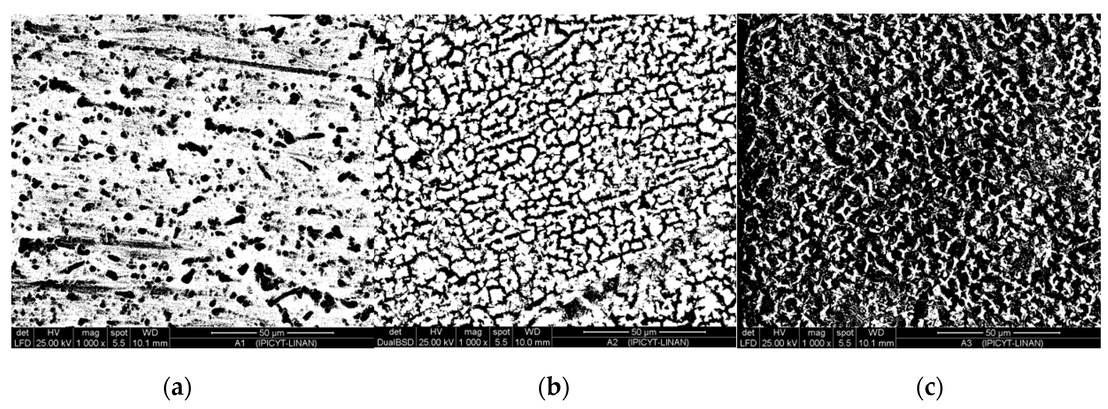
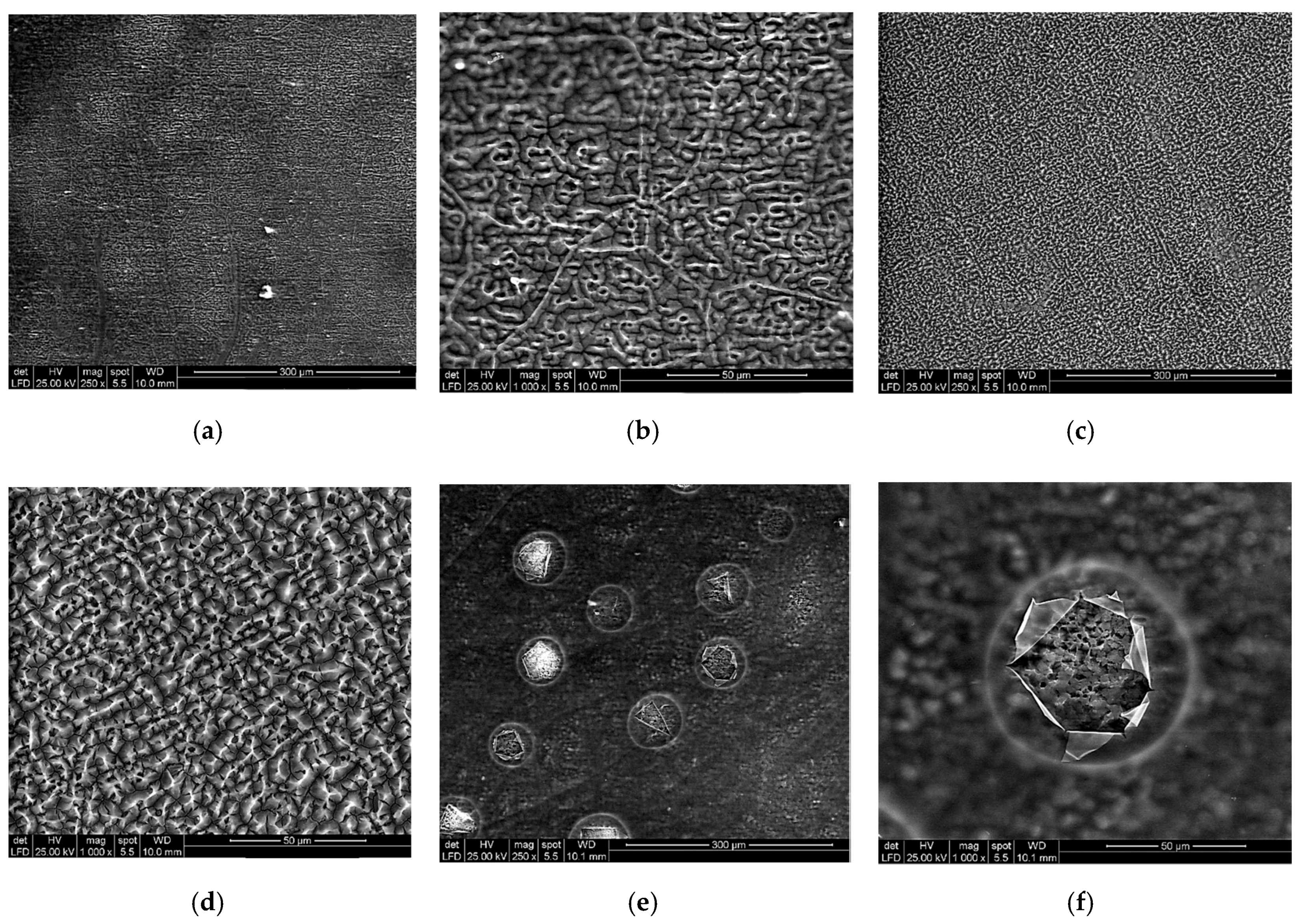
3.1. Microstructural Characterization of Inorganic-Organic Composite Coatings

The anodic aluminum oxide (AAO) films were morphological characterized by SEM in order to identify microscopic pores, cavities, and cracks, which may act as defects increasing the electrochemical corrosion susceptibility. It is well-known that the corrosion resistance of anodized aluminum depends on the layer thickness and on the final quality of the sealed surface [40]. Then, it is expected that one of the main functions of the polymeric coating is to seal the surface, which increases the corrosion resistance consequently. Figure 3a–c shows the anodic film at 0.1 A/cm2 for magnifications of 250× (Figure 3a) and 1000× (Figure 3b); as can be seen, the anodic film is homogenous. However, at 5000× a considerable space between the Al2O3 grains is observed, which may increase pitting corrosion susceptibility. The estimated grain size in the AA6063 (1) sample is about 4 µm.
The micrographs depicted in Figure 4 correspond to the Al-6063 (2) sample AAO film, which was produced by increasing the current density twice the value of the Al-AA6063 (1) sample. A less homogeneous film can be observed at 1000× and 5000× magnifications (Figure 4a,b). The difference between the current density of 0.1 and 0.2 A/cm2 is that the pitting observed at 0.2 A/cm2 is more severe and the electrolyte can infiltrate through the passive film, which may promote low adhesion of the polymer to the substrate, and the corrosion products that have been obtained by the infiltration can cause a low corrosion performance, hence the condition at 0.1 A/cm2 is considered.
By using an image analysis software, porous area was calculated for the uncoated alloy and the further anodized 0.1 and 0.2 A/cm2 current density samples. Figure 5a–c shows the porous area. The total area inspected was of 12,100 µm2 for 1kX magnification. Figure 5a depicts a porous area of 26.085%, while Figure 5b shows a porous area of 39.792%, and the Figure 5c shows a 72.313% porous area. Based on the porous area results, as mentioned above, the 0.1 A/cm2 condition was selected to achieve a linking interface, maintaining a larger nonporous area.
It is important to mention that the chitosan, Q1 and Q2 samples showed a porous percentage below 5%. In contrast the Q3 sample showed a mean porous percentage of 32%, depending on the observed position on the sample area, since the porous on the film was not distributed homogenously.
After the application of the conversion coating, three samples of Al-6063(1) were subjected to the electrophoretic deposition of the chitosan-sodium alginate solutions (Q-1, Q-2, and Q-3). In Figure 6a,b, the obtained organic film using the Q-1 solution show several ramifications that seem to be affected by the AAO film. The polymeric film obtained by the usage of Q-2 solution shows the absence of the polymeric ramifications (Figure 6c,d). Both films obtained by Q-1 and Q-2 show a homogenous and constant coating. Lastly, the obtained Q-3 film (Figure 6e,f) shows several shattered bubbles on the organic film because of the hydrogen evolution on the cathode during the electrophoretic deposition.
Finally, two control samples were prepared as described in the experimental methodology section, which corresponds to Al-6063/chitosan (aluminum sample without conversion coating and only chitosan organic film as seen in Figure 7a,b) and Al-6063 (1)/chitosan (aluminum sample with a coating system of AAO and chitosan organic film).

3.2. Corrosion Performance of Anodized and Coated Samples

Figure 8 illustrates the potentiodynamic polarization results of the aluminum-coated samples. When compared to the substrate, the corrosion potential (Ecorr) of the coated samples shifted to a more noble potential, which indicates a decrease in its corrosion susceptibility (see Table 3).
The potentiodynamic polarization curves comparison of the anodized samples and the untreated Al-6063 depicted in the Figure 8, where the potential region for the cathodic branch of the untreated aluminum alloy and anodized varies from −1.3 to −2.5 V and the open circuit potential is located around −1.3 to −1.25 V. Besides, the cathodic branch of the depicted samples corresponds to the oxygen reduction reaction. Furthermore, it can be seen that the decrease in the applied potential has negligible effect on the reaction rate, and hence in the measured current.
The polarization behavior among the chitosan-coated sample (Al-AA6063/chitosan) exhibited a cathodic passivation along with hydrogen evolution promoted by the chitosan, which shows an unstable passivation behavior that is kinetically slow; and the anodized and chitosan coated sample (Al-AA6063(1)/chitosan) exhibited similar Ecorr and lower Icorr values when compared to the uncoated sample (see Figure 8). However, it can be noted that the cathodic and anodic branches change significantly, indicating that the corrosion mechanism in the NaCl electrolyte is affected by the hydrogen evolution reaction and the oxygen reduction reaction in the NaCl solution.
It is evident that the anodized and chitosan-coated sample exhibited the lowest corrosion protection compared to the chitosan-sodium alginate coating because of the pitting potential of almost 0.0 V after passivation. It has been reported that the blending of the two polymers results in the spontaneous formation of polyion complex (PIC) because of the occurrence of ionic crosslinking, which improves specific properties such as structural strength thermal and mechanical stability along with corrosion resistance improvement and self-healing properties, and also a swelling reduction [41]. Apparently, the Al-AA6063(1)/Q-2 shows improved corrosion protection, since the pitting potential after passivation is close to 0.0 V as mentioned above, which is a more positive pitting potential (noble) when compared to the other samples.
According to Curioni and Scenini [42], during polarization in the presence of chlorides, anodic current induces a rupture of the anodic oxide film, which is localized and promotes the formation of an aluminum chloride film. Therefore, the anodic current may be close or far to the corrosion front. Then, in the pre-corroded regions, where enrichment of nobler alloying elements as Al3+, will enhances the cathodic activity promoting the bonds between the COO- and free Al3+, therefore inhibiting the hydrogen evolution and preventing the corrosion.
On the other hand, the lone pairs of electrons of the –OH groups can be adsorbed on the anodic sites of the metal surface via interaction with the vacant orbital of aluminum to inhibit the anodic metal dissolution [43,44,45], which can be seen as the increasing passivation behavior observed in the polarization curves depicted below (see Figure 9).

3.3. Corrosion Protection Efficiency of the Inorganic-Organic Composite Coating

From potentiodynamic testing, it was found that the corrosion behavior of the aluminum, was in good agreement with Fayomi et al. [46] findings, where a continuous dissolution can be observed for the uncoated aluminum alloy in the 3% NaCl electrolyte and similar values for icorr, Ecorr, and Rp were obtained, it is important to mention that the icorr value obtained by Fayomi et al. is in the order of 9.75 µA/cm2 or 9.75 × 10⁻⁶ A/cm2, which value is in accordance to this research work. Also, Fayomi et al. reported a Rp of 1.54 KΩ·cm2, a similar value can be depicted at file one in Table 3 of this research work. The inhibition efficiency of the Al2O3-chitosan-sodium alginate composite coating was estimated by using Equation (1) [47]:
n p ( % ) = ( I c o r r I c o r r 0 I c o r r ) × 100
where Icorr and I c o r r 0 are the corrosion current densities in the absence and presence of the composite coating, respectively. The calculated values of coating corrosion inhibition efficiency are depicted in Table 3.
It is important to mention the methodology employed in this research work to calculate the “polarization resistance,” considering that is not resistance in a common way as the name depicts. The linear dependency of potential on current is due to the difference between two logarithmic functions of current that approximates a linear function, only when the functions are from the same magnitude order. Then, using the Stern and Geary [38] method to calculate the polarization resistance, which results from the derivation of Equations (2) and (3) [37,38,48,49], but also can be observed experimentally and was validated by Skold et al. [50],
R p = B I c o r r = Δ E Δ i Δ E 0
where B is the proportionality constant for the corrosion system and icorr is its corrosion current density units in µA/cm2. The B constant can be calculated by Equation (3) empirically from the anodic and cathodic slopes of the corresponding Tafel plot. The Tafel constants (ba and bc) are evaluated and estimated trough experimentation or reported values for a given material system.
B = b a b c 2.3 ( b a + b c )
The linear relation described by Equation (2) is dependent upon the independent beta values from the individual anodic and cathodic polarization curves. This method has been used and reported by several researchers [37,38,48,49,50,51,52] as a valid method to obtain the polarization resistance. The main advantage of this methodology due to the potential range investigated is close the corrosion potential, hence the applied currents are generally smaller than the corrosion current [48]. The mentioned early states that the nature of the surface is not changed significantly, and that the reactions proceed during polarization are those which occur during the corrosion process [48]. It is necessary to mention that the above method is described to determine the polarization resistance, as a consequence, corrosion rates cannot be considered a universal approach; however, there is sufficient basis in theory along with extensive evidence that the technique can be useful to obtain information related to corrosion studies and is being fully used in practice and investigation as well [37,48,49,50].

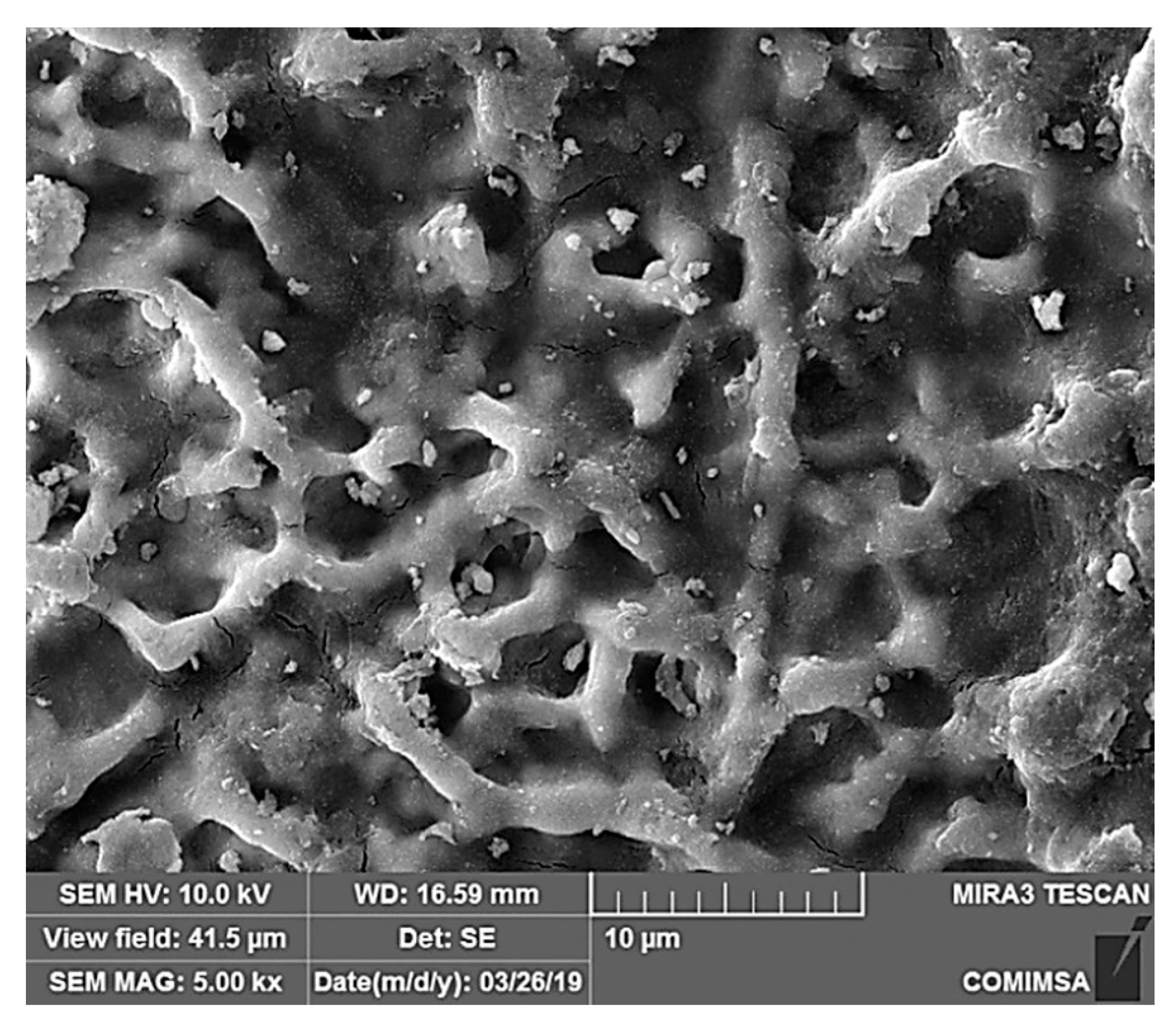
3.4. Corroded Surface Characterization after 30 Days Immersion in 3% NaCl

A set of samples which were anodized and coated with chitosan and sodium alginate corresponding to the Q1, Q2, and Q3 electrolyte preparation of the polymeric coatings, were exposed to 3% NaCl solution during a lapse of 30 days, in order to identify the corrosion mechanisms of the corresponding coatings. As it is discussed in the Section 3.3 (Potentiodynamic performance), the observed corroded surface morphologies correspond to the potentiodynamic performance, were the uncoated and the anodized and chitosan coated samples showed the lowest corrosion protection, which can be seen in Figure 10 and Figure 11. In Figure 10, the observed corroded surface corresponds to a common behavior of aluminum 6060 alloy, which at is corrosion initiation exhibits a continuous dissolution until pitting starts and a stable pit growing phenomenon its observed, when observing Figure 10, it is clear that a trench morphology because of severe pitting damage is not yet shown at 30 days of exposure. Figure 11 shows the paths where corrosion progresses on corroded surface of the aluminum alloy because of pitting on preferential sites, after the infiltration of the corrosive electrolyte, the corrosion starts in depth and later expands to the surface [53,54]. Although there is variation in the polarization resistance from uncoated, anodized, and anodized-chitosan samples, this variation is minimal and does not represent a significative change of polarization behavior, therefore, similar morphologies are observed.
When making a porous percentage area (due to pitting) calculation on the SEM images considering a 12,100 µm2 at 1000× magnification, it can be observed that the uncoated and chitosan coated samples exhibited an approximately 4.97% of its area with developed porous because of pitting corrosion, it is important to mention that the Q3 sample exhibited an approximately 27.739% porous area, while Q1 and Q2 less than 0.442%. The obtained percentages are in good agreement, since Q3 exhibited a pitting potential like uncoated sample in contrast to a 0.0 V approximately for Q1 and Q2.
The Figure 11, Figure 12 and Figure 13 show the corroded surface of the anodized and chitosan-sodium alginate blended films on AA6063.
As it was discussed above, the Q1 and Q2 coated samples exhibited a more noble pitting potential up to 0.0 V. However, the Q3 condition exhibited a pitting potential similar to uncoated and chitosan coated samples as seen in Figure 8 and Figure 9, which is in good agreement with the potentiodynamic results obtained and SEM morphology examination of Figure 10, Figure 11 and Figure 14 were similar morphological aspects of corrodes surface is observed.

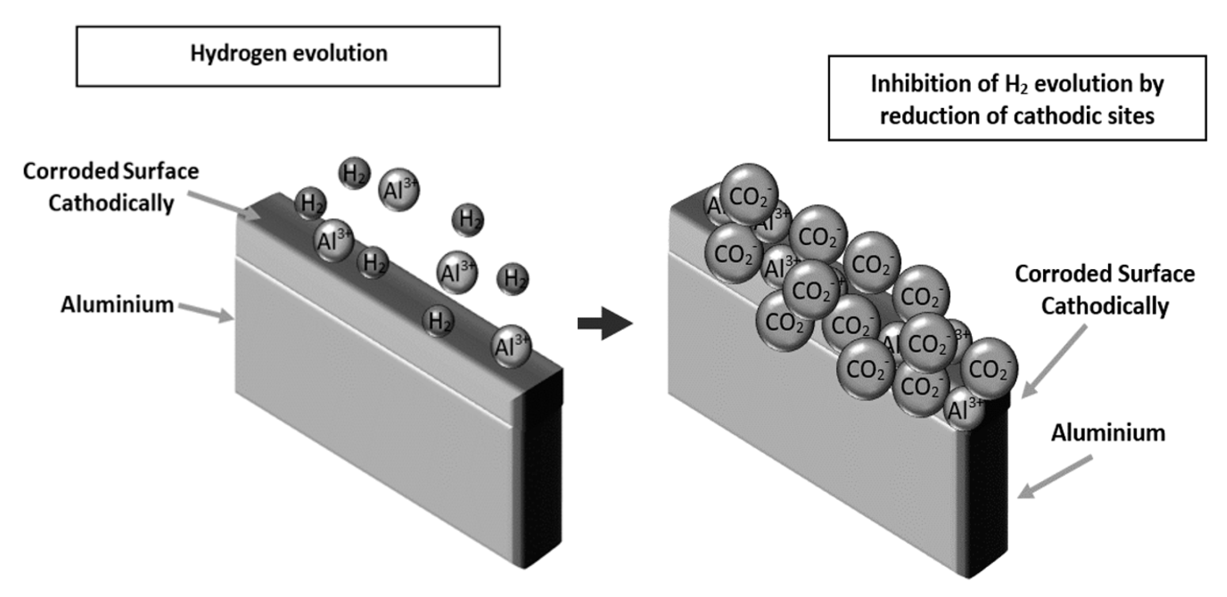
3.5. Corrosion Mechanism Insights

It is evident that the anodized and chitosan coated sample exhibited the lowest corrosion protection compared to the chitosan-sodium alginate coating because of the pitting potential of almost 0.0 V after passivation. This has been achieved by blending sodium alginate onto chitosan to overcome the disadvantage of the chitosan as well as to combine the good features of both homopolymers. In literature, it is possible to find that the blending of the two polymers results in the spontaneous formation of a polyion complex (PIC) due to ionic crosslinking, that improves specific properties such as structural strength thermal and mechanical stability along with corrosion resistance improvement and self-healing properties, and also reducing the swelling [41]. Seemingly, the Al-AA6063 (1)/Q-2 shows improved corrosion protection, since the pitting potential after passivation is close to 0.0 V as mentioned above, which is a more positive pitting potential (noble) when compared to the other samples.
Results obtained show that further research must be carried on to elucidate if the corrosion mechanism is a mixed one; since, it has been previously reported by several researchers that the chitosan has the reactive amino and hydroxyl groups [55,56,57,58]. Also, it is well-known that the sodium alginate exhibits excellent performance as a membrane material as well as the chitosan [59,60]. In this research, alginate has been blended with chitosan as mentioned above. Several authors, have reported that the polyelectrolytes prepared from chitosan and alginates show a crosslinking mechanism in blended films (first inhibition mechanism), which has been characterized by X-ray diffraction [41,61,62], the reported works deals with the intermolecular distances between the intersegmental chains after crosslinking forming polyion complexes (PIC) and the change in the crystal structure [41]. Some authors have also reported that the addition of acidic solutions aids in inducing the ion complexation between the cationic and anodic groups of chitosan and sodium alginate respectively [41,63]; the aforementioned discoveries are key to develop self-healing polymeric coatings, which are being studied by the research team. As an insight based on the evidence found in the reported literature, the free carboxylic groups of the alginic acid chains [64] are mostly present as carboxylates. Furthermore, the amino groups of the chitosan are protonated; the latter assumptions are in good agreement with Mikhailov et al. [65] and Wang et al. [35] discoveries.
The above, results in the formation of new salt bonds [43,44,45] that offers an increase in the polarization resistance, which may lead to the possible self-healing mechanism because of the crosslinking among chitosan and sodium alginate (first inhibition mechanism) as previously discussed. This linkage was performed upon mixing the carboxyl residues of alginate and the amino groups of chitosan ionically, which interacts to form the polyelectrolyte complex [66]. As discussed above, the PIC is formed through ionic interactions between the oppositely charged carboxylates and the amino groups, which typically forms an unordered polymeric network [67]. The formation of an alginate-chitosan PIC is usually performed under a pH range between 3.5 up to 6.5, where both polymers are soluble.
Hence, some of the carboxylates or amino groups are protonated and adsorbed on the cathodic or anodic sites of the aluminum alloy, because of the formation of new salt bonds (second inhibition mechanism); which inhibited the cathodic hydrogen evolution reaction as can be seen in Figure 15.
The use of sodium alginate and chitosan as anticorrosive coatings is a consequence of an emerging research field during the last few decades [68].
Also, it has been stated by Curioni and Scenini [42] that during polarization in the presence of chlorides, the anodic current induces a rupture of the anodic oxide film, which is localized and promotes the formation of an aluminum chloride film. This film is less stable when compared to the Al2O3 film and usually not homogenous and provokes some regions of the aluminum surface to be exposed directly to the electrolyte. The aforementioned process causes hydrogen evolution, or the film may be thin enough to allow electron tunneling that allows the evolution of hydrogen from the film-solution interface (see Figure 15 hydrogen evolution). Therefore, the anodic current may be close or far to the main corrosion front. Then, in the pre-corroded regions, due to the enrichment of nobler alloying elements as Al3+, will enhance the cathodic activity that promotes bonding between the COO and free Al3+, then consequently, inhibiting the hydrogen evolution and preventing corrosion.
On the other hand, the lone pairs of electrons of the –OH groups can be adsorbed on the anodic sites of the metal with the vacant orbital of aluminum, hence the inhibition of the anodic metal dissolution is prevented [43,44,45], obtaining an increase of the passivation behavior, which can be observed in the polarization curves depicted in Figure 9. It is evident that the information explained promotes that further research may be carried out to clearly elucidate the corrosion protection mechanism.

4. Conclusions

The results of the present investigation demonstrate the feasibility of using the developed anticorrosive composite coating system, composed of an inorganic interphase (Al2O3) and an organic polymeric film, to protect aluminum alloys against chloride corrosive ions species. From the results of potentiodynamic polarization and coating performance, it can be concluded that:
  • The chitosan-coated sample exhibited the maximum polarization resistance; however, its corrosion mechanism was a continuous dissolution without a noticeable passivation behavior as shown in Figure 8 and described in Section 3.2.
  • The anodized samples exhibited an almost negligible corrosion resistance improvement with an unstable passivation behavior superior to the uncoated sample as can be seen in Figure 8 at a current density range between 0.01 and 0.01 μA/cm2. Furthermore, the addition of the chitosan film stabilized the passivation behavior of the anodized samples because of the sealing of the alumina pores eliminating the chaotic behavior of anodized samples
  • Finally, the anodized and chitosan-alginate coated samples exhibited a corrosion protection efficiency above 99% and increased the pitting passivation potential up to 0.0 V as depicted in Figure 9. The chitosan-alginate coated samples exhibited a passivation behavior in contrast to the chitosan-coated sample, which may be due to the blending of the two polymers that results in the spontaneous formation of polyion complex (PIC) because of the occurrence of ionic crosslinking as explained is Section 3.5.
  • The main corrosion mechanism proposed is that the protonated carboxylates and amino groups are deposited on the cathodic or anodic sites, respectively during the deposition and potentiodynamic polarization tests because of the Al3+ ions that enhances the cathodic activity.

Author Contributions

“Cconceptualization, J.M.; methodology, A.G.-M.; software, J.M. and A.G.-M.; validation, J.M., A.G.-M. and J.P.-C.; formal analysis, A.G.-M., S.A.S., J.M. and J.P.-C.; investigation, A.G.-M., E.-J.G.-C. and V.H.M.-L.; resources, J.M. and A.G.-M.; data curation, M.H.-H.; writing—original draft preparation, A.G.-M.; writing—review and editing, S.A.S., I.L., E.-J.G.-C., V.H.M.-L., H.A.-G., M.H.-H., J.P.-C., J.M. and M.D.A.M.; visualization, V.H.M.-L. and H.A.-G.; supervision, J.M.; project administration, J.M.; funding acquisition, A.G.-M. All authors have read and agreed to the published version of the manuscript.” Please turn to the CRediT taxonomy for the term explanation. All authors have read and agreed to the published version of the manuscript.

Funding

This research was funded by Cátedras CONACYT by project grant number 674 and 850.

Acknowledgments

J. Mayen, A. Gallegos, and E. Gutiérrez duly recognize the support from CONACyT through the program Cátedras CONACYT. Support from I.Q. Candy Guadalajara Rivera and I.B.P. Rodrigo Camarena Rangel is greatly appreciated.

Conflicts of Interest

The authors declare no conflict of interest.

References

  1. Starke, E.A.; Staley, J.T. Application of modern aluminum alloys to aircraft. Prog. Aerosp. Sci. 1996, 32, 131–172. [Google Scholar] [CrossRef]
  2. Polmear, I.J. Light Alloy; Butterworth-Heinemann: Oxford, UK, 2017; pp. 299–365. [Google Scholar] [CrossRef]
  3. Davis, J.R. Aluminum and Aluminum Alloys. Light Met. Alloy. 2001, 66. [Google Scholar] [CrossRef]
  4. Suresh, S.; Vasudévan, A.K.; Bretz, P.E. Mechanisms of Slow Fatigue Crack Growth in High Strength Aluminum Alloys: Role of Microstructure and Environment. Metall. Trans. A 1984, 15, 369–379. [Google Scholar] [CrossRef]
  5. JScully, R.; Gebert, A.; Payer, J.H. Corrosion and related mechanical properties of bulk metallic glasses. J. Mater. Res. 2007, 22, 302–313. [Google Scholar] [CrossRef]
  6. Li, J.F.; Birbilis, N.; Li, C.X.; Jia, Z.Q.; Cai, B.; Zheng, Z.Q. Influence of retrogression temperature and time on the mechanical properties and exfoliation corrosion behavior of aluminium alloy AA7150. Mater. Charact. 2009, 60, 1334–1341. [Google Scholar] [CrossRef]
  7. Jones, D.A. Principles and Prevention of Corrosion; Prentice Hall: Upper Saddle River, NJ, USA, 1996. [Google Scholar]
  8. Montemor, M.F. Functional and smart coatings for corrosion protection: A review of recent advances. Surf. Coat. Technol. 2014, 258, 17–37. [Google Scholar] [CrossRef]
  9. Assem, L.; Zhu, H. Chromium Toxicological Overview; Institute of Environment and Health, Cranfield University, Health Protection Agency: Bedfordshire, UK, 2013. [Google Scholar]
  10. McKeen, L.W. Substrates and Substrate Preparation. In Fluorinated Coatings Finish; Elseviar: Amsterdam, The Netherlands, 2006. [Google Scholar] [CrossRef]
  11. Cha, S.C.; Erdemir, A. (Eds.) Coating Technology for Vehicle Applications; Springer: Basel, Switzerland, 2015. [Google Scholar]
  12. Djokić, S.S. Electrodeposition and Surface Finishing; Springer: New York, NY, USA, 2014. [Google Scholar]
  13. Kendig, M.W.; Buchheit, R.G. Corrosion inhibition of aluminum and aluminum alloys by soluble chromates, chromate coatings, and chromate-free coatings. Corrosion 2003, 59, 379–400. [Google Scholar] [CrossRef]
  14. DeVito, S.C. Present and future regulatory trends of the United States environmental protection agency. Prog. Org. Coat. 1999, 35, 55–61. [Google Scholar] [CrossRef]
  15. Jianqi, H.; Hong, H.; Lieping, S.; Genghua, G. Journal of Oral and Maxillofacial, Undefined 2002. Comparison of Calcium Alginate Film with Collagen Membrane for Guided Bone Regeneration in Mandibular Defects in Rabbits, Elsevier. Available online: https://www.sciencedirect.com/science/article/pii/S0278239102006432 (accessed on 8 August 2018).
  16. Suzuki, Y.; Nishimura, Y.; Tanihara, M.; Suzuki, K.; Nakamura, T.; Shimizu, Y.; Yamawaki, Y.; Kakimaru, Y. Evaluation of a novel alginate gel dressing: Cytotoxicity to fibroblastsin vitro and foreign-body reaction in pig skinin vivo. J. Biomed. Mater. Res. 1998, 39, 317–322. [Google Scholar] [CrossRef]
  17. Suzuki, K.; Suzuki, Y.; Tanihara, M.; Ohnishi, K.; Hashimoto, T.; Endo, K.; Nishimura, Y. Reconstruction of rat peripheral nerve gap without sutures using freeze-dried alginate gel. J. Biomed. Mater. Res. 2000, 49, 528–533. [Google Scholar] [CrossRef] [Green Version]
  18. Shilpa, A.; Agrawal, S.S.; Ray, A.R. Controlled Delivery of Drugs from Alginate Matrix. J. Macromol. Sci. Part C Polym. Rev. 2003, 43, 187–221. [Google Scholar] [CrossRef]
  19. Jmiai, A.; El Ibrahimi, B.; Tara, A.; El Issami, S.; Jbara, O.; Bazzi, L. Alginate biopolymer as green corrosion inhibitor for copper in 1M hydrochloric acid: Experimental and theoretical approaches. J. Mol. Struct. 2018, 1157, 408–417. [Google Scholar] [CrossRef]
  20. Obot, I.B.; Onyeachu, I.B.; Kumar, A.M. Sodium alginate: A promising biopolymer for corrosion protection of API X60 high strength carbon steel in saline medium. Carbohydr. Polym. 2017, 178, 200–208. [Google Scholar] [CrossRef] [PubMed]
  21. Rajput, S.D.; Gite, V.V.; Mahulikar, P.P.; Thamke, V.R.; Kodam, K.M.; Kuwar, A.S. Renewable source based non-biodegradable polyurethane coatings from polyesteramide prepared in one-pot using oleic acid. J. Am. Oil Chem. Soc. 2014, 91, 1055–1063. [Google Scholar] [CrossRef]
  22. Qian, B.; Song, Z.; Hao, L.; Wang, W.; Kong, D. Self-Healing Epoxy Coatings Based on Nanocontainers for Corrosion Protection of Mild Steel. J. Electrochem. Soc. 2017, 164, C54–C60. [Google Scholar] [CrossRef]
  23. Heise, S.; Virtanen, S.; Boccaccini, A.R. Tackling Mg alloy corrosion by natural polymer coatings—A review. J. Biomed. Mater. Res. Part A 2016, 104, 2628–2641. [Google Scholar] [CrossRef]
  24. Koch, G.H.; Brongers, M.P.; Thompson, N.; Virmani, Y.P.; Payer, J. Corrosion Cost and Preventative Strategies in the United States; Federal Highway Administration Washington: Washington, DC, USA, 2002.
  25. Jones, A.S.; Rule, J.D.; Moore, J.S.; Sottos, N.R.; White, S.R. Life extension of self-healing polymers with rapidly growing fatigue cracks. J. R. Soc. Interface 2007, 4, 395–403. [Google Scholar] [CrossRef] [Green Version]
  26. Keller, M.W.; White, S.R.; Sottos, N.R. Torsion fatigue response of self-healing poly (dimethylsiloxane) elastomers. Polymer 2008, 49, 3136–3145. [Google Scholar] [CrossRef]
  27. Pang, X.; Zhitomirsky, I. Electrophoretic deposition of composite hydroxyapatite-chitosan coatings. Mater. Charact. 2007, 58, 339–348. [Google Scholar] [CrossRef]
  28. Bumgardner, J.D.; Wiser, R.; Gerard, P.D.; Bergin, P.; Chestnutt, B.; Marini, M.; Ramsey, V.; Elder, S.H.; Gilbert, J.A. Chitosan: Potential use as a bioactive coating for orthopaedic and craniofacial/dental implants. J. Biomater. Sci. Polym. Ed. 2003, 14, 423–438. [Google Scholar] [CrossRef]
  29. Rusu, V.M.; Ng, C.H.; Wilke, M.; Tiersch, B.; Fratzl, P.; Peter, M.G. Size-controlled hydroxyapatite nanoparticles as self-organized organic-inorganic composite materials. Biomaterials 2005, 26, 5414–5426. [Google Scholar] [CrossRef] [PubMed]
  30. Chen, F.; Wang, Z.C.; Lin, C.J. Preparation and characterization of nano-sized hydroxyapatite particles and hydroxyapatite/chitosan nano-composite for use in biomedical materials. Mater. Lett. 2002, 57, 858–861. [Google Scholar] [CrossRef]
  31. Yamaguchi, I.; Iizuka, S.; Osaka, A.; Monma, H.; Tanaka, J. The effect of citric acid addition on chitosan/hydroxyapatite composites. Coll. Surf. A Physicochem. Eng. Asp. 2003, 214, 111–118. [Google Scholar] [CrossRef]
  32. Cheong, M.; Zhitomirsky, I. Electrodeposition of alginic acid and composite films. Aspects 2008, 328, 73–78. [Google Scholar] [CrossRef]
  33. Carneiro, J.; Tedim, J.; Ferreira, M.G.S. Chitosan as a smart coating for corrosion protection of aluminum alloy 2024: A review. Prog. Org. Coat. 2015, 89, 348–356. [Google Scholar] [CrossRef]
  34. HWG, H, The Anodic Oxidation of Aluminium and its Alloys. Nature 1941, 147, 659. [CrossRef]
  35. Wang, Z.; Zhang, X.; Gu, J.; Yang, H.; Nie, J.; Ma, G. Electrodeposition of alginate/chitosan layer-by-layer composite coatings on titanium substrates. Carbohydr. Polym. 2014, 103, 38–45. [Google Scholar] [CrossRef]
  36. DropSens, Electorchemical Software. Available online: https://www.metrohm.com/es/productos/potenciostatos/dropview-software-de-electroquimica/DropView8400 (accessed on 27 December 2019).
  37. Sun, Y.P.; Yang, C.T.; Yang, C.G.; Xu, D.K.; Li, Q.; Yin, L.; Qiu, C.S.; Liu, D.; Yang, K. Stern—Geary Constant for X80 Pipeline Steel in the Presence of Different Corrosive Microorganisms. Acta Metall. Sin. Lett. 2019, 32, 1483–1489. [Google Scholar] [CrossRef] [Green Version]
  38. Stern, M.; Geary, A.L. Electrochemical Polarization. J. Electrochem. Soc. 1957, 104, 559. [Google Scholar] [CrossRef]
  39. Redepenning, J.; Venkataraman, G.; Chen, J.; Stafford, N. Electrochemical preparation of chitosan/hydroxyapatite composite coatings on titanium substrates. J. Biomed. Mater. Res. A 2003, 66, 411–416. [Google Scholar] [CrossRef] [Green Version]
  40. Suay, J.J.; Giménez, E.; Rodríguez, T.; Habbib, K.; Saura, J.J. Characterization of anodized and sealed aluminium by EIS. Corros. Sci. 2003, 45, 611–624. [Google Scholar] [CrossRef]
  41. Smitha, B.; Sridhar, S.; Khan, A.A. Chitosan–sodium alginate polyion complexes as fuel cell membranes. Eur. Polym. J. 2005, 41, 1859–1866. [Google Scholar] [CrossRef]
  42. Curioni, M.; Scenini, F. The Mechanism of Hydrogen Evolution During Anodic Polarization of Aluminium. Electrochim. Acta 2015, 180, 712–721. [Google Scholar] [CrossRef]
  43. Yıldız, R.; Doğan, T.; Science, I.D.-C. Evaluation of Corrosion Inhibition of Mild Steel in 0.1 M HCl by 4-amino-3-hydroxynaphthalene-1-sulphonic acid, Elsevier. Available online: https://www.sciencedirect.com/science/article/pii/S0010938X14001887 (accessed on 9 October 2018).
  44. El-Haddad, M.N.; Fouda, A.S. Inhibition Effect and Adsorption Behavior of New Azodye Derivatives on Corrosion of Carbon Steel in Acid Medium. J. Dispers. Sci. Technol. 2013, 34, 1471–1480. [Google Scholar] [CrossRef]
  45. Umoren, S.; Obot, I.; Polymers, A.M.-C. Performance Evaluation of Pectin as Ecofriendly Corrosion Inhibitor for X60 Pipeline Steel in Acid Medium: Experimental and Theoretical Approaches, Elsevier. Available online: https://www.sciencedirect.com/science/article/pii/S0144861715001502 (accessed on 9 October 2018).
  46. Fayomi, O.S.I.; Abdulwahab, M.; Popoola, A.P.I.; Asuke, F. Corrosion resistance of AA6063-Type Al-Mg-Si alloy by silicon carbide in sodium chloride solution for marine application. J. Mar. Sci. Appl. 2015, 14, 459–462. [Google Scholar] [CrossRef]
  47. Halambek, J.; Bubalo, M.C.; Redovnikovic, I.R.; Berkovic, K. Corrosion behaviour of aluminium and AA5754 alloy in 1% acetic acid solution in presence of laurel oil. Int. J. Electrochem. Sci. 2014, 9, 5496–5506. [Google Scholar]
  48. Roberge, P.R. Handbook of Corrosion Engineering; McGraw-Hill: New York, NY, USA, 2000. [Google Scholar] [CrossRef] [Green Version]
  49. Macías, A. Comparison of different electrochemical techniques for corrosion-rate determination of zinc-coated reinforcements in simulated concrete pore solutions. Mater. Struct. 1991, 24, 456–465. [Google Scholar] [CrossRef]
  50. Skold, R.V.; Larson, T.E. Measurement of the Instantaneous Corrosion Rate By Means of Polarization Data. Corrosion 1957, 13, 69–72. [Google Scholar] [CrossRef] [Green Version]
  51. Roberge, P.R. Principles and Practice. In Corrosion Engineering; Mcgraw-hill: New York, NY, USA, 2008. [Google Scholar] [CrossRef]
  52. Magalhães, A.A.; Margarit, I.C.; Mattos, O. Electrochemical characterization of chromate coatings on galvanized steel. Electrochim. Acta 1999, 44, 4281–4287. [Google Scholar] [CrossRef]
  53. Zakaulla, M.; Khan, A.R.A.; Mukunda, P.G. Effect of Electroless Copper Coating on the Corrosion Behavior of Aluminium Based Metal Matrix Composites Reinforced with Silicon Carbide Particles. J. Miner. Mater. Charact. Eng. 2014, 2, 21–25. [Google Scholar] [CrossRef] [Green Version]
  54. Mandel, M.; Krüger, L. Long-term Corrosion Studies of a CFRP/EN AW-6060-T6 Self-piercing rivet Joint and a Steel/EN AW-6060-T6 Blind Rivet Joint. Mater. Today Proc. 2015, 2, 2959–2967. [Google Scholar] [CrossRef]
  55. Uragami, T.; Okazaki, K.; Matsugi, H.; Miyata, T. Structure and permeation characteristics of an aqueous ethanol solution of organic-Inorganic hybrid membranes composed of poly(vinyl alcohol) and tetraethoxysilane. Macromolecules 2002, 35, 9156–9163. [Google Scholar] [CrossRef]
  56. Uragami, T.; Katayama, T.; Miyata, T.; Tamura, H.; Shiraiwa, T.; Higuchi, A. Dehydration of an ethanol/water azeotrope by novel organic-Inorganic hybrid membranes based on quaternized chitosan and tetraethoxysilane. Biomacromolecules 2004, 5, 1567–1574. [Google Scholar] [CrossRef] [PubMed]
  57. Nawawi, M.G.M.; Huang, R.Y.M. Pervaporation dehydration of isopropanol with chitosan membranes. J. Membr. Sci. 1997, 124, 53–62. [Google Scholar] [CrossRef]
  58. Dashtimoghadam, E.; Hasani-Sadrabadi, M.M.; Moaddel, H. Structural modification of chitosan biopolymer as a novel polyelectrolyte membrane for green power generation. Polym. Adv. Technol. 2010, 21, 726–734. [Google Scholar] [CrossRef]
  59. Uragami, T.; Takigawa, K. Permeation and separation characteristics of ethanol-water mixtures through chitosan derivative membranes by pervaporation and evapomeation. Polymer 1990, 31, 668–672. [Google Scholar] [CrossRef]
  60. Shi, Y.; Wang, X.; Chen, G. Pervaporation characteristics and solution-diffusion behaviors through sodium alginate dense membrane. J. Appl. Polym. Sci. 1996, 61, 1387–1394. [Google Scholar] [CrossRef]
  61. Riccardo, R. Water-absorbent polymers: A patent survey. J. Macromol. Sci. Part C 1994, 34, 607–662. [Google Scholar] [CrossRef]
  62. Peppas, N.A.; Khare, A.R. Preparation, structure and diffusional behaviour of hydrogels in controlled release. Adv. Drug Deliv. Rev. 1993, 11, 1–35. [Google Scholar] [CrossRef] [Green Version]
  63. Cárdenas, A.; Argüelles-Monal, W.; Goycoolea, F.M.; Higuera-Ciapara, I.; Peniche, C. Diffusion through Membranes of the Polyelectrolyte Complex of Chitosan and Alginate. Macromol. Biosci. 2003, 3, 535–539. [Google Scholar] [CrossRef]
  64. Daemi, H.; Barikani, M. Synthesis and characterization of calcium alginate nanoparticles, sodium homopolymannuronate salt and its calcium nanoparticles. Sci. Iran. 2012, 19, 2023–2028. [Google Scholar] [CrossRef] [Green Version]
  65. Mikhailov, G.P.; Tuchkov, S.V.; Lazarev, V.V.; Kulish, E.I. Complexation of chitosan with acetic acid according to Fourier transform Raman spectroscopy data. Russ. J. Phys. Chem. A 2014, 88, 936–941. [Google Scholar] [CrossRef]
  66. George, M.; Abraham, T.E. Polyionic hydrocolloids for the intestinal delivery of protein drugs: Alginate and chitosan—A review. J. Control. Release 2006, 114, 1–14. [Google Scholar] [CrossRef] [PubMed]
  67. Lawrie, G.; Keen, I.; Drew, B.; Chandler-Temple, A.; Rintoul, L.; Fredericks, P.; Grøndahl, L.; Lawrie, G. Interactions between Alginate and Chitosan Biopolymers Characterized Using FTIR and XPS. Biomacromolecules 2007, 8, 2533–2541. [Google Scholar] [CrossRef]
  68. Umoren, S.A.; Eduok, U.M. Application of carbohydrate polymers as corrosion inhibitors for metal substrates in different media: A review. Carbohydr. Polym. 2016, 140, 314–341. [Google Scholar] [CrossRef]
Figure 1. Experimental array for the anodization process.
Coatings 10 00045 g001
Figure 2. Experimental array for the electrophoretic deposition.
Coatings 10 00045 g002
Figure 3. (a) Anodic-aluminum-oxide (AAO) film obtained at 0.1 A/cm2 during 30 min of anodizing time; (b) 1000× magnification of the AAO film; and (c) 5000× magnification of the AAO film, where a granular morphology can be observed.
Coatings 10 00045 g003
Figure 4. (a) Anodic-aluminum-oxide (AAO) film obtained at 0.2 A/cm2 during 30 min of anodizing time; (b) 1000× magnification of the AAO film; and (c) 5000× magnification of the AAO film, which exhibits a dendrite like growth.
Coatings 10 00045 g004
Figure 5. The 8-bitmap images to determine the porous area of (a) uncoated sample, (b) 0.1 A/cm2 sample, and (c) 0.2 A/cm2. Black area corresponds to porous or cracks.
Coatings 10 00045 g005
Figure 6. Inorganic-organic composite coating system of Al2O3/chitosan-sodium alginate, AAO coated with polymeric solution. The ramifications of the polymeric coating porous free can be seen in (a) AAO coated with Q-1 polymeric solution (250× magnification); (b) AAO coated with Q-1 polymeric solution (1000× magnification); (c) AAO coated with Q-2 polymeric solution (250× magnification); (d) AAO coated with Q-2 polymeric solution (1000× magnification); while (e) AAO coated with Q-3 polymeric solution (250× magnification); (f) AAO coated with Q-3 polymeric solution (1000× magnification), showing the shattered bubbles no homogenously dispersed on the surface samples, which are considered as porous areas that promotes the infiltration of the corrosive medium to the conversion coating.
Coatings 10 00045 g006
Figure 7. Control sample of aluminum AA6063 alloy coated with a chitosan film, images taken at magnifications of: (a) 100× and (b) 250×.
Coatings 10 00045 g007
Figure 8. Potentiodynamic polarization curves of AA6063 aluminum alloy as a function of processing parameters.
Coatings 10 00045 g008
Figure 9. Potentiodynamic polarization curves for the Al-6063 alloy and the Al2O3/chitosan-sodium alginate.
Coatings 10 00045 g009
Figure 10. Corroded surface of uncoated sample.
Coatings 10 00045 g010
Figure 11. Corroded surface of anodized and chitosan coated sample.
Coatings 10 00045 g011
Figure 12. Anodized and chitosan-sodium alginate (Q1 electrolyte).
Coatings 10 00045 g012
Figure 13. Anodized and chitosan-sodium alginate (Q2 electrolyte).
Coatings 10 00045 g013
Figure 14. Anodized and chitosan-sodium alginate (Q3 electrolyte).
Coatings 10 00045 g014
Figure 15. Schematic representation of the second inhibition mechanism because of the formation of salt bonds, which prevents the cathodic hydrogen evolution, when sodium alginate is used in the developed coating.
Coatings 10 00045 g015
Table 1. Studied coating systems.
SampleCoating
Al-6063Uncoated
Al-6063(1)Anodized
Al-6063/chitosanChitosan
Al-6063(1)/chitosanAnodized and chitosan
Al-6063(1)/Q-1Anodized and chitosan-sodium alginate (using solution Q-1)
Al-6063(1)/Q-2Anodized and chitosan-sodium alginate (using solution Q-2)
Al-6063(1)/Q-3Anodized and chitosan-sodium alginate (using solution Q-3)
Table 2. Constant current parameters for anodizing procedure.
SampleCurrent (A/cm2)
Al-AA6063 (1)0.1
Al-AA6063 (2)0.2
Table 3. Potentiodynamic polarization parameters obtained after testing in 3% NaCl electrolyte.
SamplesEcorr (V)Icorr (µA/cm2)ba (V/dec)bc (V/dec)BRp (KOhm cm2) Eq. xRp (KOhm cm2) DropViewnp (%)
Al-6063−1.39722.360.110.4538.381.7171.693---
Al-6063 (1)−1.2915.460.050.2718.323.3573.12886.53
Al-6063 (2)−1.3657.960.0710.4426.553.3343.35932.11
Al-6063/chitosan−0.6980.080.300.4275.99971.339978.454
Al-6063 (1)/chitosan−1.342.090.080.3728.5613.69713.13281.83
Al-6063 (1)/Q-1−1.1450.230.220.3357.32253.546254.55799.01
Al-6063 (1)/Q-2−1.1920.180.220.3961.08334.804336.80698.95
Al-6063 (1)/Q-31.1140.300.300.9097.70332.308335.67598.77

