Article

Superconducting HfO2-YBa2Cu3O7−δ Nanocomposite Films Deposited Using Ink-Jet Printing of Colloidal Solutions

1
Department of Chemistry, Sol-Gel Centre for Research on Inorganic Powders and Thin Films Synthesis (SCRiPTS), Ghent University, Krijgslaan 281-S3, 9000 Ghent, Belgium
2
Karlsruhe Institute of Technology, Institute for Technical Physics, Hermann-von-Helmholtz-Platz 1, 76344 Eggenstein-Leopoldshafen, Germany
*
Author to whom correspondence should be addressed.
Coatings 2020, 10(1), 17; https://doi.org/10.3390/coatings10010017
Submission received: 20 November 2019 / Revised: 22 December 2019 / Accepted: 24 December 2019 / Published: 26 December 2019
(This article belongs to the Special Issue Superconducting Films and Nanostructures)

Abstract

:
To reduce the fabrication costs while maximizing the superconducting and pinning properties of YBa2Cu3O7−δ (YBCO) nanocomposite films, the drop-on-demand ink-jet printing technique was used to deposit colloidal YBCO inks onto LaAlO3 substrates. These inks containing preformed HfO2 nanocrystals were carefully adjusted, prior to the jettability, as the droplet formation depends on the rheological properties of the inks themselves. After carefully adjusting printing parameters, 450-nm thick pristine YBCO films with a self-field critical current density (Jc) of 2.7 MA cm² at 77 K and 500-nm thick HfO2-YBCO nanocomposite films with a self-field Jc of 3.1 MA·cm² at 77 K were achieved. The final HfO2-YBCO nanocomposite films contained dispersed BaHfO3 particles in a YBCO matrix due to the Ba2+ reactivity with the HfO2 nanocrystals. These nanocomposite films presented a more gradual decrease of Jc with the increased magnetic field. These nanocomposite films also showed higher pinning force densities than the pristine films. This pinning enhancement was related to the favorable size and distribution of the BaHfO3 particles in the YBCO matrix.

1. Introduction

In recent years, one of the biggest challenges in the field of applied superconductivity has been the low-cost and scalable processing of high-quality YBa2Cu3O7−δ (YBCO) nanocomposite films for long-length production in order to meet the requirements of power applications [1]. Up to now, most of the textured superconducting YBCO thin films with a critical temperature of 93 K and the desired properties for a coated conductor architecture are realized via vacuum processes, such as pulsed laser deposition (PLD) and metal-organic chemical vapor deposition (MOCVD) [2,3,4]. These deposition methods require costly high-vacuum systems, which are not so attractive at the industrial scale [5]. Therefore, there is a great demand for the reduction of fabrication costs of YBCO-coated conductors. The chemical solution deposition (CSD) method is a non-vacuum technique that fulfills the demand as a cost-effective, high yield, and easy-to-scale method. CSD is considered to be one of the most promising routes for the fabrication of highly textured ceramic oxides with functional properties, such as ferroelectricity [6], magneto-resistance [7], and conductivity [8]. Several research groups have already demonstrated that CSD is suitable for the fabrication of coated conductors [9,10,11].
In order to diversify the use of CSD-based YBCO nanocomposite films to certain power applications, the drastic decrease of the critical current density (Jc) at moderate‑to-high magnetic fields has to be prevented, and the Jc anisotropy with the magnetic field orientation has to be minimized by introducing nanometer-sized defects in the YBCO matrix [12]. Several authors have reported on PLD-grown YBCO nanocomposite films with non-superconducting compounds, such as nanocolumns and nanodots, which result in a good in-field performance [13,14,15,16,17,18]. However, the pathway to fabricating low-cost CSD-grown films with relevant pinning properties does not seem straightforward because of the necessity to solve several critical issues related to YBCO nanocomposite growth. There are several papers in the literature concerning the limited control of the formation and size distribution of self-assembled nanoparticles (in situ approach) in the YBCO matrix in CSD [19,20,21]. These nanocomposite films show improved in-field performances compared to pristine YBCO films, but face some difficulties, such as reproducibility or low values of the pinning force density compared to the PLD-grown nanocomposite films. To increase the reproducibility, some attempts were already made with several preformed nanocrystals (ex situ approach), yielding both trifluoroacetic- and low-fluorine-based YBCO nanocomposite films with a successful increase of the pinning force densities [22,23,24,25]. Unfortunately, the values are still lower compared to the YBCO nanocomposites prepared using the in situ approach with BaZrO3 particles [26]. Since the size and distribution of nanometer-sized defects control the pinning force ability, the Hf-containing compounds appear more attractive than Zr-containing compounds. When introducing Hf-containing compounds in PLD-grown nanocomposite films, the size and distribution of BaHfO3 nanocolumns in the YBCO matrix lead to an improvement of the pinning properties [27]. To our knowledge, this is the first study involving the incorporation of HfO2 nanocrystals in CSD-grown YBCO nanocomposite films.
Nowadays, most CSD processes in academic projects start with methanol-based YBCO precursor solutions for the fabrication of YBCO thin-films via spin- or dip-coating [1,28]. Spin-coating is commonly used as a lab-scale deposition technique because of its simplicity, but it shows a limited scalability with regard to the continuous processing of superconducting films. In contrast to spin-coating, the reel-to-reel deposition techniques, such as spraying, slot-die coating, dip-coating, and ink-jet printing, can further increase the industrial feasibility [29]. The drop-on-demand ink-jet printing is used in this work since this technique offers a better control of the deposition process by means of easy delivery of small droplets in defined positions, allowing for an accurate control of the film thickness. Furthermore, it enables the deposition of full and patterned coatings. These patterned coatings are an attractive alternative to the striation or etching of the superconducting film [30,31]. It has been shown before that the ink-jet printing method can offer the possibility of high resolution patterning to reduce alternating current (AC) loss issues for electric power applications [10,32].
Methanol is often used as a solvent because of good wettability on the substrate [9,32]. When methanol-based precursor solutions are employed for ink-jet printing, clogging of the nozzle will occur due to fast desiccation and flocculation (Figure 1A) owing to the low boiling point of methanol [33]. This means that cleaning the nozzle regularly is necessary to avoid nozzle blocking. To prevent this cleaning step during the printing session, methanol is replaced with 1-butanol as the solvent in the solutions to increase the vapor pressure and to decrease the evaporation rate [34]. Here, we show the possibility of generating a highly reproducible jettability of colloidal 1-butanol-based YBCO inks without the introduction of any additives in contrast to the YBCO inks of Obradors et al. [35], where additives, such as polymer compounds, were introduced. This additive-free deposition method is unprecedented and shows some key advantages as the thermal decomposition of the metal organic precursor is one of the critical steps in the CSD-based growth of high-quality thin-films [28]. It also enables the drop-on-demand ink-jet printing (Figure 1B) deposition of YBCO nanocomposite thin-films on substrates. This CSD route shows a high potential for low-cost, long-length industrial production (reel-to-reel deposition) on industrial Ni-W tape [36]. This comprehensive study may serve as a generic approach to use ink-jet printing technology for the fabrication of several other electrical, magnetic, and optical nanocomposite thin films.

2. Materials and Methods

2.1. YBCO Ink and Nano-Suspension Preparation and Characterization

The YBCO precursor solution was prepared by dissolving barium trifluoracetate, copper propionate, and yttrium propionate in 1-butanol with a Y:Ba:Cu ratio of 1:2:3 and a total concentration of 0.75 mol∙L−1. Monodisperse HfO2 nanocrystals were synthesized via 4 mmol HfCl4 and 4 mmol Hf(OiPr)4 in 20 g tri-n-octylphosphine oxide at 360 °C for 2 h under an argon atmosphere, in accordance with the work of Tang et al. [37]. After the heating-up synthesis, the reaction mixture was cooled to 80 °C and acetone was added (1:5 by volume) to precipitate the nanocrystals. The as-synthesized nanocrystals were purified and redispersed in an apolar solvent, e.g., toluene [38]. The crystal structure was identified via powder X-ray diffraction (PXRD) on a Thermo Scientific ARL XTra (Cu-Kα, Waltham, MA, USA), while the morphology was observed using transmission electron microscopy (TEM) on a Cs-corrected JEOL JEM-2000FS (200 kV, Tokyo, Japan). The nanocrystals’ solvodynamic diameter was determined via dynamic light scattering (DLS) analysis on a Malvern Nano ZS (Malvern, UK). To achieve a stable HfO2-YBCO ink, the nanocrystals were transferred to a polar solvent via a ligand exchange step. First, acetone (1:3 by volume) was added to the nanocrystals dispersion to precipitate the HfO2 nanocrystals. Second, the precipitate was transferred to 1-butanol via the addition of a steric dispersant (a copolymer with a phosphonate group), leading to a transparent and stable nanosuspension [24]. Finally, this nanosuspension was added to the YBCO ink with the desired molar percentage (5 or 10 mol%). The density of the pristine and HfO2-YBCO inks were analyzed using a 10 mL glass pycnometer (Duran, Wertheim/Main, Germany) and the viscosity was analyzed with a Brookfield DV-E viscometer (Middelboro, MA, USA) (25 °C and 100 rpm). The surface tension of both inks and their contact angles on LaAlO3 were characterized with a Drop Shape Analyzer DSA30 (Krüss GmbH, Hamburg, Germany). The contact angles were measured using 0.5-µL droplets.

2.2. Thin-Film Deposition and Thermal Treatment

Prior to ink-jet printing, the (100)-oriented LaAlO3 single crystal substrates were cleaned with isopropanol and heated to 400 °C to improve the wettability. The substrates were coated using a piezoelectric drop-on-demand ink-jet system (Dimatix DMP 2800, Dimatix-Fujifilm Inc., Santa Clara, CA, USA) equipped with a 10-pL cartridge (DMCLCP-11610, a 22-µm orifice and 16 nozzles). All coatings were achieved by printing lines with a droplet spacing of 25 µm using a customized printing waveform (see Supplementary Material) and a longitudinal spacing between each printed line of 25 µm. The maximum voltages of the waveforms for both cases, jetting and non-jetting, were adjusted for pristine and HfO2-YBCO inks prior to printing. Pristine YBCO inks were printed in a reproducible way with a print frequency of 12 kHz using the customized waveform with the ejection voltage applied to the piezoelectric nozzle in the range of 17–18 V for the jetting waveform and 9–10 V for the non-jetting waveform. The firing voltage of the piezoelectric nozzles was increased to 18–19 V with a lower print frequency of 9 kHz for the HfO2-YBCO inks. The single- or multi-printed layers were dried at 85 °C on a hotplate in ambient atmosphere for 5 min and subsequently pyrolyzed by heating to 400 °C with a heating rate of 3–5 °C∙min−1 in a humidified O2 atmosphere. To obtain the desired superconducting film, the pyrolyzed YBCO films were subsequently exposed to a two-step, high-temperature thermal treatment at 640 °C for 60 min (nucleation) and at 800 °C for 70 min (growth) in a humid 100 ppm O2 in N2 atmosphere, which was switched to dry O2 at 450 °C for 2 h during the annealing step [39].

2.3. Structural and Electrical Characterization

The texture quality and phase composition of the pristine and HfO2-YBCO films were investigated by means of XRD on a Bruker (Billerica, MA, USA) D4 diffractometer (Cu-Kα). The surface morphology and the film microstructure in the cross-section were analyzed using a FEI (Hillsboro, OR, USA) Nova 600 Nanolab Dual Beam focused ion beam (FIB) scanning electron microscope (SEM). For further microstructural analysis, a cross-sectional TEM lamella was obtained using ion milling techniques via the FIB in situ lift-out procedure [40]. High-resolution (HR) TEM images were taken using a Cs-corrected JEOL JEM-2200FS TEM operated at 200 kV. The image processing software ImageJ version 1.51j8 was used for the statistical measurement of particles in cross-sectional TEM images. The critical current density Jc in the self-field (sf) at 77 K of the YBCO films was obtained via inductive measurements using a THEVA (Ismaning, Germany) Cryoscan with a voltage criterion of 50 µV. Critical transport currents were measured in a 14-T Quantum Design Physical Property Measurement System (San Diego, CA, USA) in a maximum Lorentz force configuration on laser-cut bridges (800-μm length, 15−20-μm width) with an electrical field criterion of 1 µV·cm−1. The pinning force density was calculated using the following equation: F p   =   J c B . The orientation dependence of the critical current density, Jc(B,θ), with θ being the angle between sample normal and magnetic field, was measured at 30 K and 77 K by rotating the sample in applied magnetic fields of 1 T and 5 T between 280° and 80° with steps of 2° near B‖ab and 5° around B‖c.

3. Results

3.1. Physical Properties of the Pristine and HfO2-YBCO Inks

For high-temperature superconducting applications, it is necessary to reach high critical currents. Apart from the explained benefits of the nanocrystal addition as artificial pinning centers, this can also be achieved by increasing the superconducting layer thickness. One possibility for increasing the thickness is through ink-jet printing multi-deposition [34]. However, in order to achieve proper jetting (Figure 1A), fluid properties, such as viscosity, density, and surface tension, must be taken into consideration. The nanocrystals should also be agglomerate-free and stable in the YBCO ink. The jettability of droplets in a drop-on-demand print head can be predicted through its fluid dynamics, as characterized by the Ohnesorge number (Equation (1)):
O h   =   η ( γ ρ α ) 1 .
This number is related to the Reynolds and the Weber numbers and consists of viscosity η (Pa∙s), surface tension γ (N∙m−1), and density ρ (kg∙m−3) of the ink, along with the orifice diameter of the nozzle α (m). The inverse value of the Ohnesorge number (Oh−1), being independent of the droplet velocity, should be between 1 and 10 to achieve stable jetting properties [10,41]. As shown in Table 1, the pristine YBCO ink with a concentration of 0.75 mol L−1 had a viscosity of 6.4 ± 0.1 mPa∙s and a surface tension of 22.13 ± 0.16 mN∙m−1, determined at 21 °C, which yielded an Oh−1 value of 3.23.
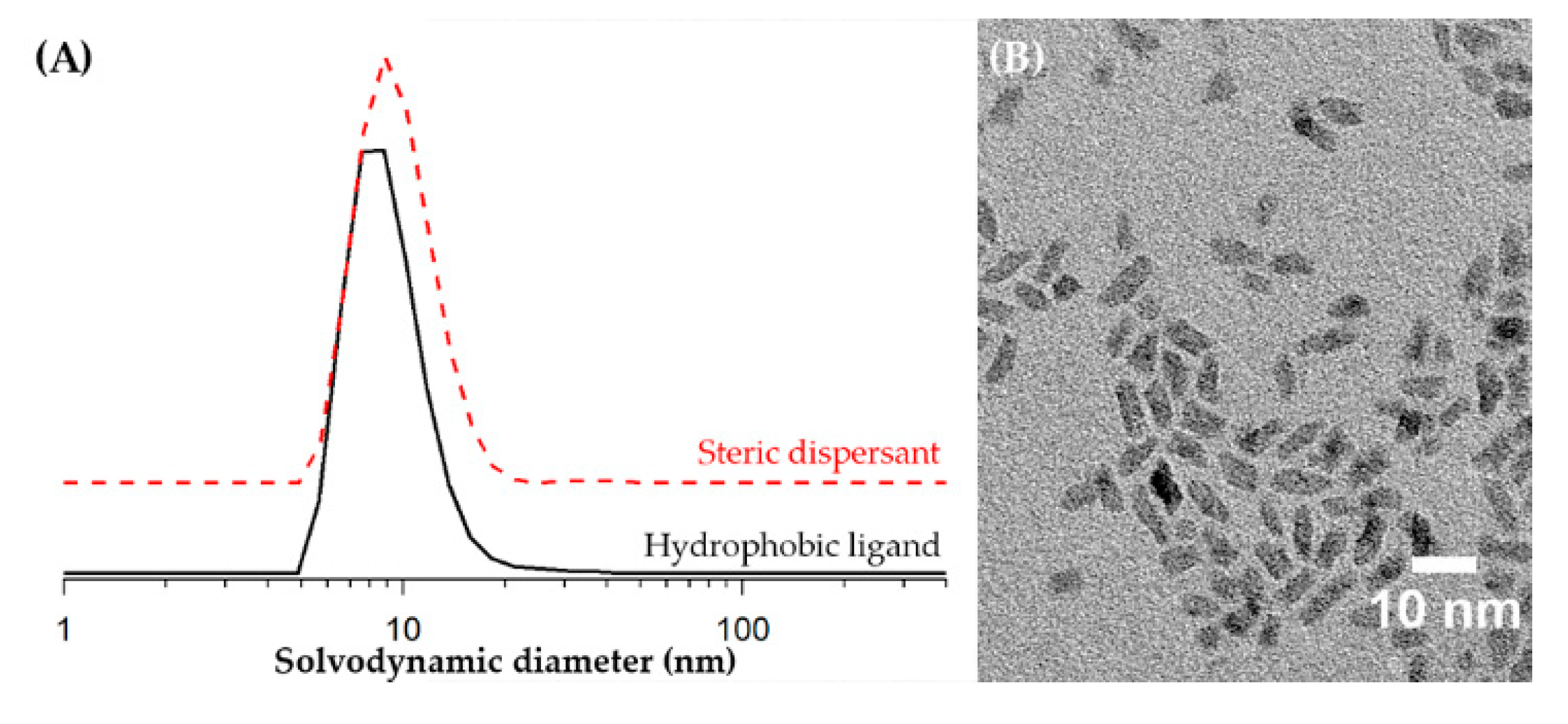
To study the fluid properties after the addition of HfO2 nanocrystals to the pristine ink, the HfO2 nanocrystals were synthesized and purified, resulting in agglomerate-free HfO2 nanocrystals capped with hydrophobic phosphorus-containing ligands in toluene with a solvodynamic diameter of 10.2 nm, as determined via DLS (Figure 2A) [37]. The nanocrystals had nanorod-like morphology with a diameter of 2.6 nm and a length of 8 nm according to TEM (Figure 2B), and the monoclinic phase was recognized via PXRD (Figure S1). However, the YBCO precursor provided a highly ionic and polar environment. Thus, a careful ligand exchange was needed to transfer and redisperse the as-synthesized nanocrystals into a polar solvent without any precipitation or agglomeration [38,42]. The HfO2 nanocrystals were stabilized agglomerate-free in a polar solvent (e.g., 1-butanol) and YBCO ink when using a steric dispersant with phosphonate groups. This ligand exchange/phase transfer yielded a solvodynamic diameter of 10.7 nm, as confirmed via DLS measurements (Figure 2A).
YBCO ink nanosuspensions with 5 and 10 mol% HfO2 nanocrystal concentration were used to study their rheological properties. First, it is important to remark that the solvodynamic diameter of the nanocrystals must be 100 times smaller than the orifice diameter of the nozzle (a cartridge with a 22-µm orifice and 16 nozzles was used in this work) to avoid nozzle blockage (Figure 1A) [43]. As shown in Table 1, the solvodynamic diameter of HfO2 nanocrystals was acceptable for ink-jet printing without clogging. The addition of HfO2 nanocrystals to the YBCO ink slightly increased its density and surface tension while the viscosity remained constant (Table 1). This modification led to a negligible increase of the Oh−1 number as the values remained within the intended range between 1 and 10. Therefore, the nanocrystals did not affect the printability. It is noteworthy that the different inks in the cartridges were stable for at least 5 months when stored in a closed container, indicating a long shelf-life of these HfO2-YBCO inks.
In this work, we focused on the ink-jet printing deposition of pristine and 5 mol% HfO2-YBCO inks on LaAlO3 substrates. Five mol% HfO2 nanocrystals in YBCO ink was chosen as it showed good pinning properties in a previous work [24]. As shown in Figure 3A, the droplets from the pristine YBCO ink showed a tail when they were expelled from the nozzle. However, this tail later merged with the droplet to a single spherical droplet, while satellite droplets are not formed at all. The jetting analysis of the HfO2-YBCO ink displayed in Figure 3B revealed the formation of a droplet tail with very small satellite droplets (red dotted rectangle in Figure 3B), which finally merged with the main droplets. This means that the addition of nanocrystals affected the jetting behavior and its droplet formation. However, this could be managed by adjusting a printing waveform (more details in the Supplementary Material). Thus, it is clear that the printing waveform depended on the addition of nanocrystals and not only on the inverse Ohnesorge number.
After characterizing the jetting behavior of the inks, the wetting interaction between the droplets and the cleaned substrates upon impact plays a critical role in forming a homogeneous and continuous coating. The droplets should spread out easily and merge with the neighboring droplets to form a continuous wet coating. In that regard, it is extremely important that the ink shows good wetting, i.e., low contact angles. The contact angles (θC) of all inks on the cleaned LaAlO3 substrate were in the range of 14–15° (Table 1). The theoretical footprint contact diameter dcon of the drop upon impact can be estimated using the following equation [41]:
d con   =   d 0 8 tan θ C 2 ( 3   + tan 2 θ C 2 ) 3 ,
where θC is the equilibrium contact angle and d0 is the droplet diameter during flight measured via Dropwatch (Figure 3A,B, diameter of 23.9 ± 0.2 µm for both YBCO inks). The theoretical footprint contact diameter dcon was calculated to be 64 µm. The experimental contact diameter as measured using separated droplets on the LaAlO3 substrate (distance of 100 µm) with an optical micrograph (Figure 3C) was even slightly larger, in the range of 70–80 µm. This indicates that the local wetting of the droplets was good on LaAlO3 substrates.

3.2. Multi-Deposition of Pristine YBCO Inks

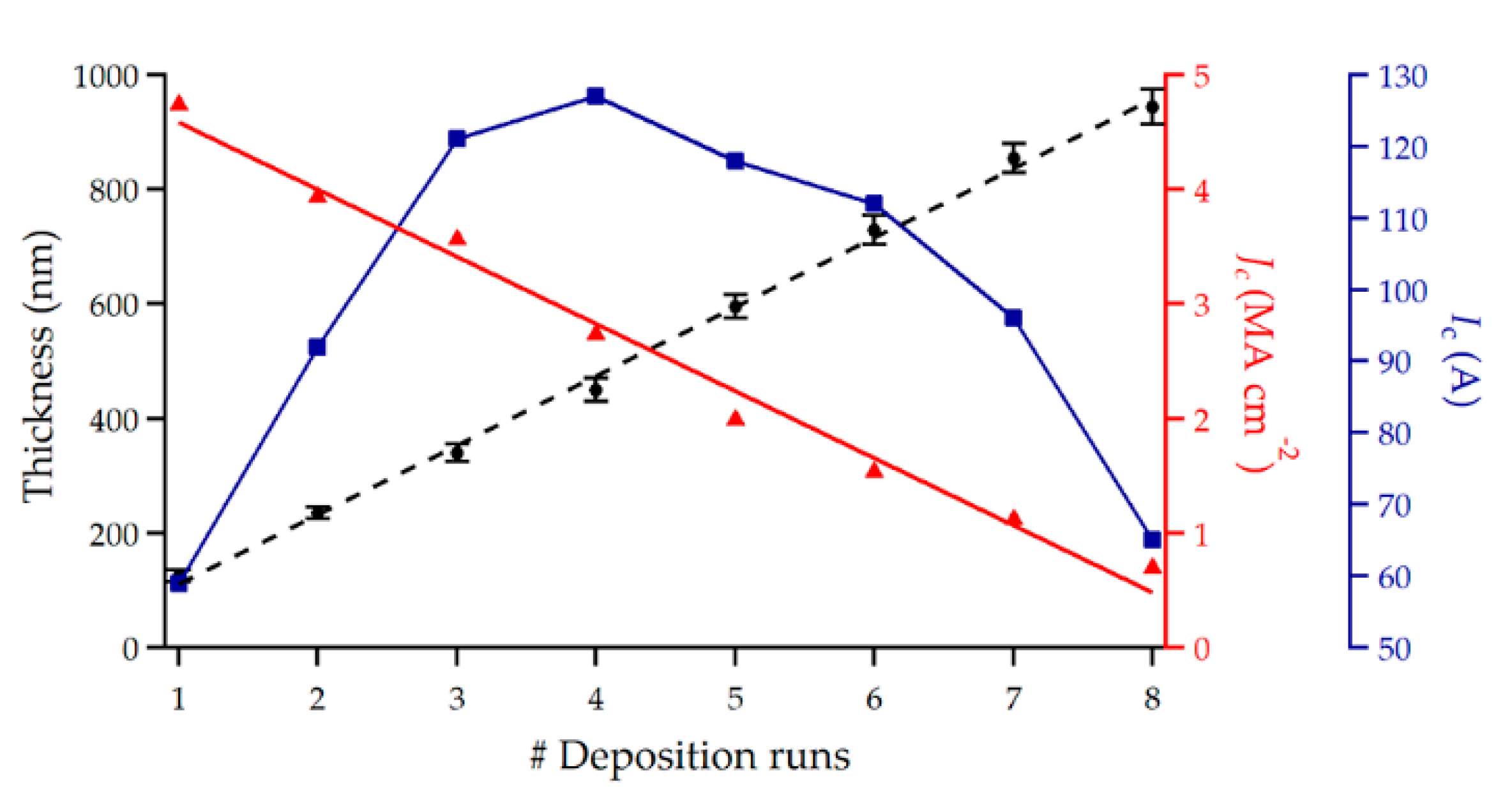
In order to obtain a smooth and continuous wet coating, a drop spacing of 25 μm in both the x- and y-direction was used to deposit a thin-film. After single-printing one layer, the wet coating was dried and subsequently thermally treated (pyrolysis, crystallization, and annealing) in the same conditions as above, leading to a thickness of 125 nm for pristine YBCO ink (verified using the cross-sectional view via SEM, Figure S3A) with an inductively measured self-field Jc of 4.74 MA∙cm² at 77 K. However, in order to increase the critical currents of the films, we explored the possibility of increasing the film thickness via multi-deposition. This process consisted of printing one layer on the LaAlO3 substrate and afterwards rotating the substrate 90° clockwise for printing the next layer. This process was repeated several times without any additional thermal process until the desired thickness was reached. This procedure of perpendicularly printing was chosen to avoid accumulation of liquid at the edges of the substrates. This liquid accumulation can lead to crack formation during the pyrolysis, which degrades the superconducting properties. By increasing the number of depositions stepwise to eight, the thickness of the pristine YBCO film was increased linearly. The properties of different pristine YBCO films with different thicknesses are shown in Figure 4. The self-field Jc at 77 K decreased with the total thickness. This was due to two main reasons. First, the increased thickness, and therefore (critical) currents, led to stronger self-fields, resulting in a stronger decrease of the self-field Jc [44]. Second, the YBCO growth starting from a thick pyrolyzed layer (obtained from single or multiple printing and finally one thermal processing) was much more challenging. The thick pyrolyzed layer had the tendency to form non-ideal microstructures, e.g., increased a/b-oriented or other misoriented grains [45,46] or pore formation [47], and therefore, lower Jc values were reached. In the films with more than four depositions, Ba(O,F)2 was present within the YBCO layer, as confirmed using XRD (Figure S4A) with 2θ = 24.9° (111), 28.9° (002), and 41.2° (202), and the cross-sectional SEM (Figure S4B) image. The presence of Ba(O,F)2 indicates that the YBCO formation was incomplete, which was not surprising considering that the employed growth process was kept constant without any further optimization for thicker films. A follow-up study should be devoted to optimizing the growth process of thicker films. Nevertheless, as clearly seen in the XRD spectrum in Figure S5A, the higher deposition numbers, e.g., four depositions, also exhibited intense YBCO (00ℓ) peaks—2θ = 30.6° (004) and 38.5° (005)—with just a small amount of secondary phases, such as BaxCuyOz (2θ = 27.7° and 42°), Y2O3 (220) at 29.9°, and Y2O3 (004) at 34.2°. No (103) misoriented YBCO grains were observed at 32.8°. The surface morphology of this four-deposition pristine YBCO film (Figure S5B) showed a small number of a/b-oriented grains. It had a dense and homogeneous cross-section (only occasionally holes were visible) with a thickness of 450 ± 15 nm (Figure S5B). This four-deposition pristine YBCO film yielded an inductively measured Jc (77 K, sf (self-field)) of 2.73 MA∙cm−2 (Table 2) and a corresponding Ic of 127 A (cm-width)−1, which is similar to the 400 nm fully trifluoroacetic-based pristine YBCO film deposited on LaAlO3 substrate with an Ic of 120 A (cm width)−1 reported by Vilardell et al. [48].

3.3. Multi-Deposition of HfO2-YBCO Inks

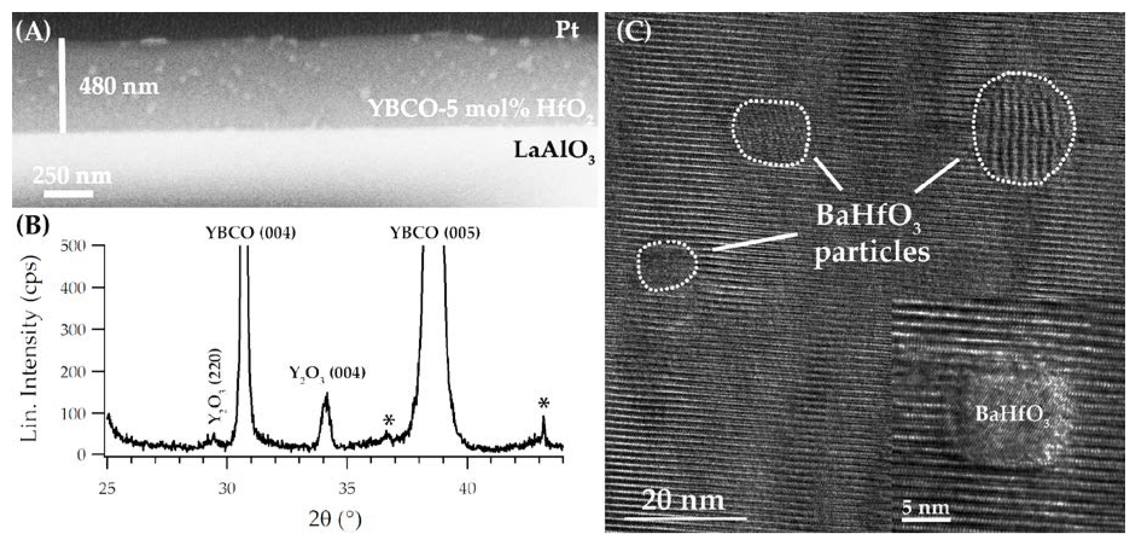
With the same printing conditions and one single deposition of 5 mol% HfO2-YBCO ink, films with a thickness of 150 nm after a full thermal process were achieved, as confirmed using a cross-sectional SEM (Figure S3B), which yielded an inductively measured Jc (77 K, sf) of 5.12 MA cm−2 and a corresponding Ic of 76 A (cm-width)−1. Here, a HfO2-YBCO nanocomposite film with a similar thickness of 450 nm, as described for the pristine YBCO film, was obtained after only three ink-jet deposition runs with a thickness of 480 ± 20 nm after a full thermal process, as confirmed in the cross-sectional SEM image shown in Figure 5A. Furthermore, this image shows a dense film with a dispersion of BaHfO3 particles (bright spots) throughout the film. In the XRD θ–2θ pattern of the 5 mol% HfO2-YBCO nanocomposite film (Figure 5B), two strong reflections of YBCO (004) and (005) and a weaker reflection of Y2O3 (004) were visible. The addition of preformed HfO2 nanocrystals resulted in self-field Jc values of 3.1 MA cm−2 and Ic values of 149 A at 77 K for the 480 nm YBCO nanocomposite film with three deposition runs. This enhancement of the self-field Jc for YBCO nanocomposite was likely due to the contracted Cu–O bonds, resulting in the increase of the pair-breaking energy [49]. The high-resolution TEM image of a HfO2-YBCO nanocomposite film (Figure 5C) shows BaHfO3 particles (indexed using the fast Fourier transform pattern, Figure S6) embedded in the YBCO matrix with mean diameters of 10.4 ± 3.9 nm. This means that HfO2 nanocrystals reacted with the Ba2+ ions, leading to the formation of BaHfO3 particles in the YBCO matrix. Nevertheless, our previous work [39] demonstrated that the reactivity of preformed ZrO2 nanocrystals results in a delay rather than in a degradation of the YBCO nucleation and growth. This growth delay can be circumvented via the introduction of an intermediate dwelling step, yielding an increase of Jc [39]. However, Pop et al. [34] has recently printed a low-fluorine-based YBCO precursor solution with additives on a LaAlO3 substrate with a final thickness of 0.6–1.2 µm via a single deposition, yielding a fairly good Jc value of 2.0–2.7 MA·cm−2 and an Ic value of 240 A at 77 K (Table 2). This work of Pop et al. shows that strict optimization of the nucleation and growth of thick YBCO nanocomposite films should be investigated for this HfO2-YBCO nanocomposite approach for power applications.

3.4. Transport Measurements of Pristine and HfO2-YBCO Films

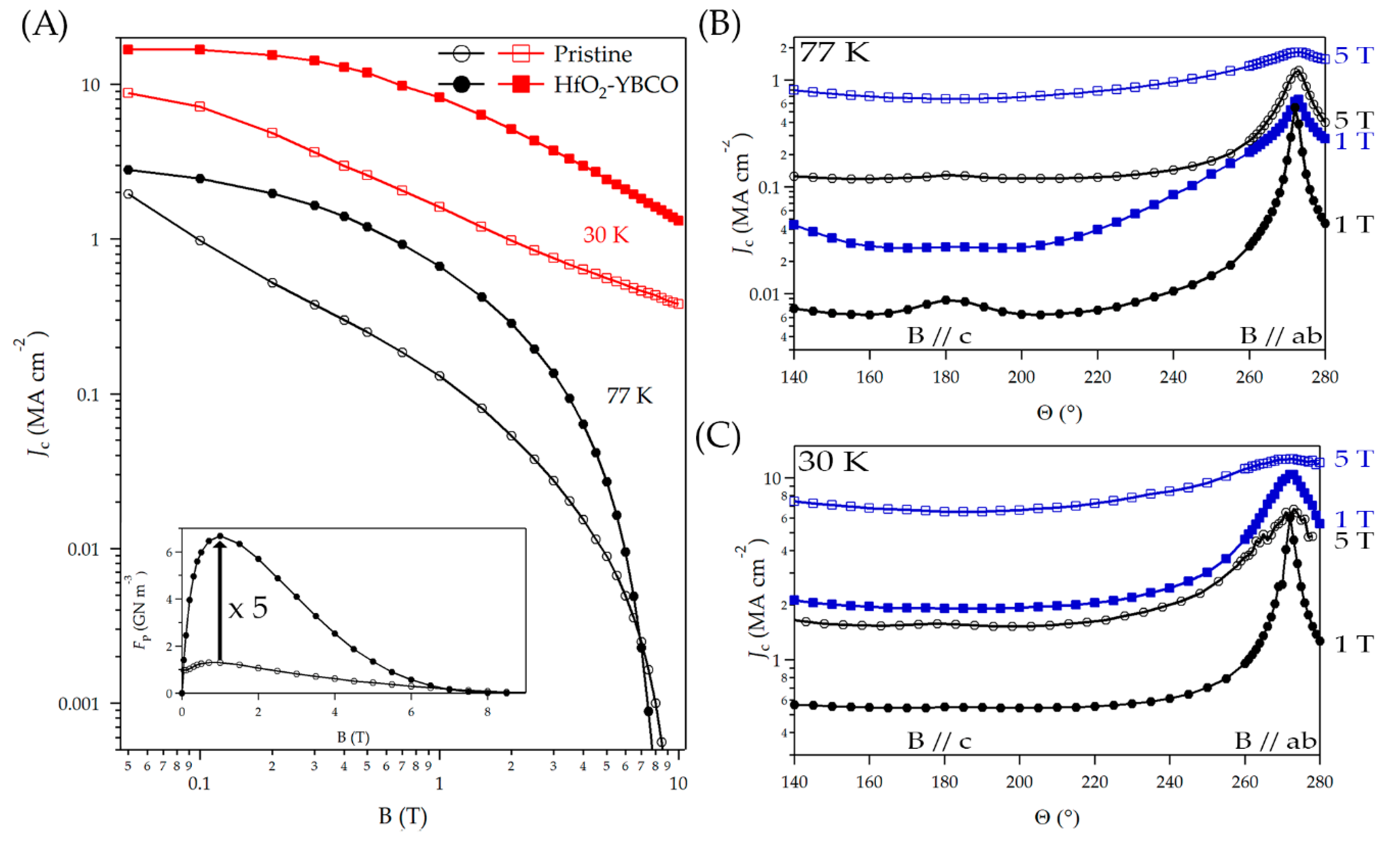
Ink-jet printing of both pristine and HfO2-YBCO films led to good in-field values of the critical current density Jc at both temperatures of 30 and 77 K (Figure 6). The effect of adding HfO2 nanocrystals on the pinning properties was clearly seen by comparing the Jc(B) curves of both films. The largest difference on Jc was found around 1 T for the magnetic field parallel to the film normal (B‖c) at 77 K (Figure 6A). This was a combined effect of the BaHfO3 particles themselves and the concurrent larger density of the twin boundaries, as shown in Figure 6. Both had corresponding matching fields in this magnetic field region. Whereas the pristine YBCO film showed a power-law exponent α value (Jc ~ B−α) of 0.89 at 77 K, the HfO2-YBCO film did not show a clear power-law behavior due to the additional contribution at around 1 T. The HfO2-YBCO film showed an α value of 0.48 when fitting the line in the range of 0 to 1 T at 77 K. The maximum pinning force densities (Fp,max) at 77 K of the pristine YBCO film of around 1.3 GN∙m−3 compares well to the value observed by Erbe et al. for similar films prepared using spin-coating trifluoroacetic‑based YBCO (Table 3) [50]. On the other hand, the 5 mol% HfO2-YBCO film created using ink-jet printing showed an Fp,max = 6.8 GN∙m−3 at 77 K, a value around 1.5 times larger than a 12 mol% self-assembled BaHfO3-YBCO nanocomposite prepared using spin-coating [50]. This was due to both the smaller density of voids and the different molar BaHfO3 concentration. Similar Fp,max values at 77 K were shown for BaZrO3-YBCO nanocomposites (Table 3), starting from preformed ZrO2 nanocrystals deposited via the trifluoroacetic route (6.0 GN∙m−3) [23] and the propionate route (7.3 GN∙m−3) [39]. However, these Fp,max values were still lower than for self-assembled BaZrO3 particles via the trifluoroacetic route (21 GN∙m−3) [26]. The incorporation of HfO2 nanocrystals in the YBCO matrix is unseen in the literature and leads to an excellent enhancement of Fp,max by a factor of 5.2. It was itself higher compared to the incorporation of ZrO2 nanocrystals in the YBCO matrix (Table 3, a factor of 3.5) [24]. This increase can be explained by the good distribution of small BaHfO3 particles with a mean diameter of 10.4 ± 3.9 nm in the YBCO matrix, whereas BaZrO3 particles in [24] showed a mean diameter of 13.0 ± 5.5 nm. This increase is also attributed to the higher number of BaHfO3 particles (1.67 × 10¹²) in YBCO volume of 0.000048 cm³ compared to the BaZrO3 particles (0.68 × 10¹²) of Rijckaert et al. [24]. The mean diameter of particles, numbers of particles, and its distribution in the YBCO matrix had a significant impact on the pinning properties. The nanocrystals should be kept as small as possible with a high number value of particles in the YBCO matrix for good pinning properties. Nevertheless, it has been shown that the use of ZrO2 and HfO2 nanocrystals as single metal oxide nanocrystals leads to the formation of double metal oxide (BaZrO3 and BaHfO3) particles, which are coarsened to larger particles during the thermal process because of the Ba2+ reactivity. This reactivity of the preformed nanocrystals could be avoided by using double-metal-oxide nanocrystals, acting as completely inert materials in the YBCO matrix. The optimization of these YBCO nanocomposite films can be accelerated by means of combinatorial methods. Concerning the thin-film deposition of oxide materials, PLD and sputtering process have been mostly applied for the creation of a continuous composition spread (CCS) [51,52,53]. The CCS method is often used to explore compositions with two or more different elements. The CCS method has the advantage of being able to grow thin-films with several dozens of compositions at a time compared with conventional solid-state synthesis [54]. It is not straightforward to use this CCS method via a CSD process because the superconducting properties depend on the YBCO ink having a Y:Ba:Cu ratio of 1:2:3. To understand the parameters that control the properties of YBCO nanocomposite films, a definitive screening design should be introduced as this is a powerful method to determine the descriptive equation of each material property with a minimal amount of experiments [55]. Further research is required to obtain homogenously distributed double-metal-oxide nanocrystals throughout the YBCO matrix with excellent superconducting properties on LaAlO3 substrates and industrial metallic templates [56].
The critical current densities were increased by the nanocrystal addition in a wide angular range around the c-axis direction by a factor of 10 at 77 K and a factor of 7 at 30 K, whereas near the ab-direction, both pristine and HfO2-YBCO films showed nearly the same values. This is comparable to the results on ZrO2 nanocrystals. Besides the ab-peak, there was a small c-axis peak that was visible, especially at 77 K. This was mainly due to correlated pinning at twin boundaries (and to some degree to extended particles). The decrease of the relative height of this peak due to the nanocrystal addition may have two reasons: First, the (small) decrease in vertical coherence of the twin boundaries led to a wider angular range where the twin boundaries were active, counterbalancing the higher twin boundary density in HfO2-YBCO films (Figure S7). Second, a larger weight of the nanocrystal contributed at intermediate angles (compare, e.g., Jc(θ) at 77 K in 5 T in the range 220°–260°), or in other words, the smaller effective gamma value (not shown here) [22] hid the c-axis peak. The transport Jc measurements illustrated that ink-jet printing is a suitable method for chemical solution (multi)-deposition of YBCO-based thin-films and nanocomposites, which has great potential for the scalable production of high-quality superconducting films for energy applications, such as rotating machines.

4. Conclusions

The chemical solution deposition method was used to obtain YBCO nanocomposite films using an ex situ approach with improved pinning performances. It was shown that the deposition of colloidal YBCO inks via a drop-on-demand piezoelectric ink-jet printing technique is possible. The use of this deposition technique required the adjustment of the printing waveform for every solution to make sure that the jettability was adequate. After this adjustment, it could deposit pristine and HfO2-YBCO inks on single-crystal LaAlO3 substrates. This ink-jet printing technique could easily deliver small droplets in accurate positions, which allowed for a fine control of the film thickness. It made the multi-deposition of several layers possible for obtaining thicker films. It was possible to achieve epitaxial YBCO + HfO2 with further optimization up to four depositions, but above that, Ba(O,F)2 was present within the YBCO layer, indicating the YBCO formation was incomplete. A follow-up study should be devoted to optimizing the growth process of thicker films. The TEM analysis of the obtained films revealed the presence of BaHfO3 particles in the YBCO matrix, meaning that the original HfO2 nanocrystals reacted with Ba2+ ions during thermal processing. The presence of these BaHfO3 particles resulted in higher pinning force densities compared to the Zr-containing compounds due to their smaller size and homogeneous distribution in the YBCO matrix, improving the pinning performances. More effort will be necessary to transfer these results from LaAlO3 substrates to industrial metallic templates and the commercial market as there are still challenges to overcome regarding depositing the pristine and HfO2-YBCO inks due to the different wetting and growth behavior on other substrates.

Supplementary Materials

The following are available online at https://www.mdpi.com/2079-6412/10/1/17/s1: Figure S1. XRD patterns showing only reflections of the monoclinic phase after the heating-up synthesis of HfO2 nanocrystals. Figure S2. Optimized jetting and non-jetting waveforms used for printing (A) pristine and (B) HfO2-YBCO inks. Figure S3. Cross-sectional SEM image of one single deposition of YBCO (A) without and (B) with 5 mol% HfO2 nanocrystals after full thermal process. Figure S4. (A) Cross-sectional SEM view and corresponding XRD spectrum (B) of YBCO layer obtained via five deposition layers. Figure S5. Composition and microstructure after full thermal processing of an ink-jet-printed YBCO film with four deposition runs. Figure S6. Fast Fourier transform pattern of isolated BaHfO3 particles in YBCO matrix. Figure S7. (h00) bright-field TEM showing the twin boundaries of (A) pristine and (B) HfO2-YBCO layer.

Author Contributions

H.R. and K.D.B. conceived and designed the experiments; H.R. deposited the samples, made TEM measurements, and wrote this manuscript. J.D.S. made the inductive measurements; P.C. performed the XRD analysis; P.L.D. synthesized the HfO2 nanocrystals; R.N. structured the laser-cut bridges. J.H. and M.E. measured the transport properties; all authors reviewed the manuscript. I.V.D. and B.H provided supervision. All authors have read and agreed to the published version of the manuscript.

Funding

This work was financially supported by the European Union Horizon 2020 Marie Curie Actions under the project SynFoNY (H2020/2016-722071).

Acknowledgments

The authors want to thank Jelle Pelemans and Sidney Van Oosterwyck for their research contribution.

Conflicts of Interest

The authors declare no conflict of interest.

References

  1. Obradors, X.; Puig, T. Coated conductors for power applications: Materials challenges. Supercond. Sci. Technol. 2014, 27, 044003. [Google Scholar] [CrossRef]
  2. Araki, T.; Hirabayashi, I. Review of a chemical approach to YBa2Cu3O7−x-coated superconductors—metalorganic deposition using trifluoroacetates. Supercond. Sci. Technol. 2003, 16, R71–R94. [Google Scholar] [CrossRef]
  3. Stadel, O.; Muydinov, R.Y.; Brauer, G.; Rikel, M.O.; Ehrenberg, J.; Bock, J.; Kotzyba, G.; Nast, R.; Goldacker, W.; Samoylenkov, S.V. MOCVD and MOD of YBCO and buffer layers on textured metal tapes. IEEE Trans. Appl. Supercond. 2009, 19, 3160–3163. [Google Scholar] [CrossRef]
  4. Chepikov, V.; Mineev, N.; Degtyarenko, P.; Lee, S.; Petrykin, V.; Ovcharov, A.; Vasiliev, A.; Kaul, A.; Amelichev, V.; Kamenev, A. Introduction of BaSnO3 and BaZrO3 artificial pinning centres into 2G HTS wires based on PLD-GdBCO films. Phase I of the industrial R&D programme at SuperOx. Supercond. Sci. Technol. 2017, 30, 124001. [Google Scholar] [CrossRef]
  5. Bäcker, M.; Baumann, A.; Brunkahl, O.; Erbe, M.; Schneller, T. Chemical Solution Deposition (CSD). Digit. Encycl. Appl. Phys. 2019, 1–34. [Google Scholar]
  6. George, J.; Smet, P.; Botterman, J.; Bliznuk, V.; Woestenborghs, W.; Van Thourhout, D.; Neyts, K.; Beeckman, J. Lanthanide-assisted deposition of strongly electro-optic PZT thin films on silicon: Toward integrated active nanophotonic devices. ACS Appl. Mater. Interfaces 2015, 7, 13350–13359. [Google Scholar] [CrossRef] [Green Version]
  7. Van Driessche, I.; Hopkins, S.; Lommens, P.; Granados, X.; Andreouli, D.; Glowacki, B.; Arabatzis, I.M.; Arin, M.; Ricart, S.; Fasaki, I. Efficient and environmentally friendly ink-jet printing of ceramic thin films. Nanosci. Nanotechnol. Lett. 2013, 5, 466–474. [Google Scholar] [CrossRef]
  8. Vernieuwe, K.; Feys, J.; Cuypers, D.; De Buysser, K. Ink-Jet Printing of Aqueous Inks for Single-Layer Deposition of Al-Doped ZnO Thin Films. J. Am. Ceram. Soc. 2016, 99, 1353–1359. [Google Scholar] [CrossRef]
  9. Obradors, X.; Puig, T.; Pomar, A.; Sandiumenge, F.; Mestres, N.; Coll, M.; Cavallaro, A.; Romà, N.; Gázquez, J.; González, J.C.; et al. Progress towards all-chemical superconducting YBa2Cu3O7-coated conductors. Supercond. Sci. Technol. 2006, 19, S13–S26. [Google Scholar] [CrossRef]
  10. Van Driessche, I.; Feys, J.; Vermeir, P.; Lommens, P.; Hopkins, S.C.; Granados, X.; Glowacki, B.A.; Baecker, M.; Reich, E.; Ricard, S.; et al. Ink-jet printing of YBa2Cu3O7 superconducting coatings and patterns from aqueous solutions. J. Mater. Chem. 2012, 22, 3717–3726. [Google Scholar] [CrossRef] [Green Version]
  11. Pollefeyt, G.; Rottiers, S.; Vermeir, P.; Lommens, P.; Hühne, R.; De Buysser, K.; Van Driessche, I. Feasibility study of the synthesis of YBiO3 thin films by aqueous chemical solution deposition as an alternative for CeO2 buffer layers in coated conductors. J. Mater. Chem. A 2013, 1, 3613–3619. [Google Scholar] [CrossRef]
  12. Puig, T.; Gutiérrez, J.; Pomar, A.; Llordés, A.; Gazquez, J.; Ricart, S.; Sandiumenge, F.; Obradors, X. Vortex pinning in chemical solution nanostructured YBCO films. Supercond. Sci. Technol. 2008, 21, 034008. [Google Scholar] [CrossRef]
  13. MacManus-Driscoll, J.; Foltyn, S.; Jia, Q.; Wang, H.; Serquis, A.; Civale, L.; Maiorov, B.; Hawley, M.; Maley, M.; Peterson, D. Strongly enhanced current densities in superconducting coated conductors of YBa2Cu3O7–x+BaZrO3. Nat. Mater. 2004, 3, 439–443. [Google Scholar] [CrossRef] [PubMed]
  14. Matsumoto, K.; Mele, P. Artificial pinning center technology to enhance vortex pinning in YBCO coated conductors. Supercond. Sci. Technol. 2010, 23, 014001. [Google Scholar] [CrossRef]
  15. Opherden, L.; Sieger, M.; Pahlke, P.; Hühne, R.; Schultz, L.; Meledin, A.; Van Tendeloo, G.; Nast, R.; Holzapfel, B.; Bianchetti, M. Large pinning forces and matching effects in YBa2Cu3O7−δ thin films with Ba2Y(Nb/Ta)O6 nano-precipitates. Sci. Rep. 2016, 6, 21188. [Google Scholar] [CrossRef]
  16. Malmivirta, M.; Rijckaert, H.; Paasonen, V.; Huhtinen, H.; Hynninen, T.; Jha, R.; Awana, V.S.; Van Driessche, I.; Paturi, P. Enhanced flux pinning in YBCO multilayer films with BCO nanodots and segmented BZO nanorods. Sci. Rep. 2017, 7, 14682. [Google Scholar] [CrossRef] [Green Version]
  17. Rizzo, F.; Augieri, A.; Kursumovic, A.; Bianchetti, M.; Opherden, L.; Sieger, M.; Hühne, R.; Hänisch, J.; Meledin, A.; Van Tendeloo, G. Pushing the limits of applicability of REBCO coated conductor films through fine chemical tuning and nanoengineering of inclusions. Nanoscale 2018, 10, 8187–8195. [Google Scholar] [CrossRef]
  18. Khan, M.Z.; Rivasto, E.; Tikkanen, J.; Rijckaert, H.; Malmivirta, M.; Liedke, M.O.; Butterling, M.; Wagner, A.; Huhtinen, H.; Van Driessche, I. Enhanced flux pinning isotropy by tuned nanosized defect network in superconducting YBa2Cu3O6+x films. Sci. Rep. 2019, 9, 1–12. [Google Scholar] [CrossRef] [Green Version]
  19. Coll, M.; Guzman, R.; Garcés, P.; Gazquez, J.; Rouco, V.; Palau, A.; Ye, S.; Magen, C.; Suo, H.; Castro, H.; et al. Size-controlled spontaneously segregated Ba2YTaO6 nanoparticles in YBa2Cu3O7 nanocomposites obtained by chemical solution deposition. Supercond. Sci. Technol. 2014, 27, 044008. [Google Scholar] [CrossRef]
  20. Horita, H.; Teranishi, R.; Yamada, K.; Kaneko, K.; Sato, Y.; Otaguro, K.; Nishiyama, T.; Izumi, T.; Awaji, S. Miniaturization of BaHfO3 nanoparticles in YBa2Cu3Oy-coated conductors using a two-step heating process in the TFA-MOD method. Supercond. Sci. Technol. 2016, 30, 025022. [Google Scholar] [CrossRef]
  21. Miura, M.; Maiorov, B.; Sato, M.; Kanai, M.; Kato, T.; Kato, T.; Izumi, T.; Awaji, S.; Mele, P.; Kiuchi, M.; et al. Tuning nanoparticle size for enhanced functionality in perovskite thin films deposited by metal organic deposition. NPG Asia Mater. 2017, 9, e447. [Google Scholar] [CrossRef]
  22. Cayado, P.; De Keukeleere, K.; Garzón, A.; Perez-Mirabet, L.; Meledin, A.; De Roo, J.; Vallés, F.; Mundet, B.; Rijckaert, H.; Pollefeyt, G.; et al. Epitaxial YBa2Cu3O7−x nanocomposite thin films from colloidal solutions. Supercond. Sci. Technol. 2015, 28, 124007. [Google Scholar] [CrossRef] [Green Version]
  23. De Keukeleere, K.; Cayado, P.; Meledin, A.; Vallès, F.; De Roo, J.; Rijckaert, H.; Pollefeyt, G.; Bruneel, E.; Palau, A.; Coll, M.; et al. Superconducting YBa2Cu3O7−δ Nanocomposites Using Preformed ZrO2 Nanocrystals: Growth Mechanisms and Vortex Pinning Properties. Adv. Electron. Mater. 2016, 2, 1600161. [Google Scholar] [CrossRef] [Green Version]
  24. Rijckaert, H.; Pollefeyt, G.; Sieger, M.; Hänisch, J.; Bennewitz, J.; De Keukeleere, K.; De Roo, J.; Hühne, R.; Bäcker, M.; Paturi, P.; et al. Optimizing Nanocomposites through Nanocrystal Surface Chemistry: Superconducting YBa2Cu3O7 Thin Films via Low-Fluorine Metal Organic Deposition and Preformed Metal Oxide Nanocrystals. Chem. Mater. 2017, 29, 6104–6113. [Google Scholar] [CrossRef] [Green Version]
  25. Rijckaert, H.; De Roo, J.; Van Zele, M.; Banerjee, S.; Huhtinen, H.; Paturi, P.; Bennewitz, J.; Billinge, S.; Bäcker, M.; De Buysser, K. Pair Distribution Function Analysis of ZrO2 Nanocrystals and Insights in the Formation of ZrO2-YBa2Cu3O7 Nanocomposites. Materials 2018, 11, 1066. [Google Scholar] [CrossRef] [Green Version]
  26. Gutierrez, J.; Llordes, A.; Gazquez, J.; Gibert, M.; Roma, N.; Ricart, S.; Pomar, A.; Sandiumenge, F.; Mestres, N.; Puig, T. Strong isotropic flux pinning in solution-derived YBa2Cu3O7−x nanocomposite superconductor films. Nat. Mater. 2007, 6, 367–373. [Google Scholar] [CrossRef] [PubMed]
  27. Aye, M.M.; Khan, M.Z.; Rivasto, E.; Tikkanen, J.; Huhtinen, H.; Paturi, P. Role of columnar defect size in angular dependent flux pinning properties of YBCO thin films. IEEE Trans. Appl. Supercond. 2019, 29, 1–5. [Google Scholar] [CrossRef]
  28. Rijckaert, H.; De Roo, J.; Roeleveld, K.; Pollefeyt, G.; Bennewitz, J.; Bäcker, M.; Lynen, F.; De Keukeleere, K.; Van Driessche, I. Microwave-assisted YBa2Cu3O7 precursors: A fast and reliable method towards chemical precursors for superconducting films. J. Am. Ceram. Soc. 2017, 100, 2407–2418. [Google Scholar] [CrossRef]
  29. Abbel, R.; Galagan, Y.; Groen, P. Roll-to-Roll Fabrication of Solution Processed Electronics. Adv. Eng. Mater. 2018, 20, 1701190. [Google Scholar] [CrossRef] [Green Version]
  30. Sumption, M.; Collings, E.; Barnes, P. AC loss in striped (filamentary) YBCO coated conductors leading to designs for high frequencies and field-sweep amplitudes. Supercond. Sci. Technol. 2004, 18, 122. [Google Scholar] [CrossRef]
  31. Nast, R.; Vojenčiak, M.; Demencik, E.; Kario, A.; Ringsdorf, B.; Jung, A.; Runtsch, B.; Grilli, F.; Goldacker, W. Influence of laser striations on the properties of coated conductors. J. Phys. Conf. Ser. 2014, 507, 022023. [Google Scholar] [CrossRef] [Green Version]
  32. Hopkins, S.; Joseph, D.; Mitchell-Williams, T.; Calleja, A.; Vlad, V.; Vilardell, M.; Ricart, S.; Granados, X.; Puig, T.; Obradors, X. Inkjet printing of multifilamentary YBCO for low AC loss coated conductors. J. Phys. Conf. Ser. 2014, 507, 022010. [Google Scholar] [CrossRef] [Green Version]
  33. Van Driessche, I.; Feys, J.; Hopkins, S.C.; Lommens, P.; Granados, X.; Glowacki, B.A.; Ricart, S.; Holzapfel, B.; Vilardell, M.; Kirchner, A.; et al. Chemical solution deposition using ink-jet printing for YBCO coated conductors. Supercond. Sci. Technol. 2012, 25, 065017. [Google Scholar] [CrossRef]
  34. Pop, C.; Villarejo, B.; Pino, F.; Mundet, B.; Ricart, S.; de Palau, M.; Puig, T.; Obradors, X. Growth of all-chemical high critical current YBa2Cu3O7−δ thick films and coated conductors. Supercond. Sci. Technol. 2018, 32, 015004. [Google Scholar] [CrossRef]
  35. Obradors, X.; Puig, T.; Li, Z.; Pop, C.; Mundet, B.; Chamorro, N.; Valles, F.; Bau, M.C.; Ricart, S.; Villarejo, B. Epitaxial YBa2Cu3O7−x nanocomposite films and coated conductors from BaMO3 (M = Zr, Hf) colloidal solutions. Supercond. Sci. Technol. 2018, 31, 044001. [Google Scholar] [CrossRef] [Green Version]
  36. Rijckaert, H.; Van Driessche, I. Superconducting YBa2Cu3O7−δ Nanocomposite Films Using Preformed ZrO2 Nanocrystals via Chemical Solution Deposition. In Superconductivity: From Materials Science to Practical Applications; Mele, P., Prassides, K., Tarantini, C., Palau, A., Badica, P., Jha, A.K., Endo, T., Eds.; Springer International Publishing: Cham, Germany, 2020; pp. 133–167. [Google Scholar]
  37. Tang, J.; Fabbri, J.; Robinson, R.D.; Zhu, Y.; Herman, I.P.; Steigerwald, M.L.; Brus, L.E. Solid-Solution Nanoparticles: Use of a Nonhydrolytic Sol-Gel Synthesis To Prepare HfO2 and HfxZr1−xO2 Nanocrystals. Chem. Mater. 2004, 16, 1336–1342. [Google Scholar] [CrossRef]
  38. De Keukeleere, K.; Coucke, S.; De Canck, E.; Van Der Voort, P.; Delpech, F.; Coppel, Y.; Hens, Z.; Van Driessche, I.; Owen, J.S.; De Roo, J. Stabilization of Colloidal Ti, Zr, and Hf Oxide Nanocrystals by Protonated Tri-n-octylphosphine Oxide (TOPO) and Its Decomposition Products. Chem. Mater. 2017, 29, 10233–10242. [Google Scholar] [CrossRef] [Green Version]
  39. Rijckaert, H.; Hänisch, J.; Pollefeyt, G.; Bäcker, M.; Van Driessche, I. Influence of Ba2+ consumption and intermediate dwelling during processing of YBa2Cu3O7 nanocomposite films. J. Am. Ceram. Soc. 2019, 102, 3870–3878. [Google Scholar] [CrossRef]
  40. Van Zele, M.; Watté, J.; Hasselmeyer, J.; Rijckaert, H.; Vercammen, Y.; Verstuyft, S.; Deduytsche, D.; Debecker, D.; Poleunis, C.; Van Driessche, I. Thickness Characterization Toolbox for Transparent Protective Coatings on Polymer Substrates. Materials 2018, 11, 1101. [Google Scholar] [CrossRef] [Green Version]
  41. Derby, B. Inkjet printing of functional and structural materials: Fluid property requirements, feature stability, and resolution. Annu. Rev. Mater. Res. 2010, 40, 395–414. [Google Scholar] [CrossRef]
  42. De Roo, J.; Coucke, S.; Rijckaert, H.; De Keukeleere, K.; Sinnaeve, D.; Hens, Z.; Martins, J.C.; Van Driessche, I. Amino Acid-Based Stabilization of Oxide Nanocrystals in Polar Media: From Insight in Ligand Exchange to Solution 1H NMR Probing of Short-Chained Adsorbates. Langmuir 2016, 32, 1962–1970. [Google Scholar] [CrossRef] [PubMed] [Green Version]
  43. De Keukeleere, K.; Pollefeyt, G.; Feys, J.; De Roo, J.; Rijckaert, H.; Lommens, P.; Van Driessche, I. Chemical solution deposition of functional ceramic coatings using ink-jet printing. Pure Appl. Chem. 2015, 87, 231–238. [Google Scholar] [CrossRef] [Green Version]
  44. Hengstberger, F.; Eisterer, M.; Weber, H. Thickness dependence of the critical current density in superconducting films: A geometrical approach. Appl. Phys. Lett. 2010, 96, 022508. [Google Scholar] [CrossRef] [Green Version]
  45. Smith, J.; Cima, M.; Sonnenberg, N. High critical current density thick MOD-derived YBCO films. IEEE Trans. Appl. Supercond. 1999, 9, 1531–1534. [Google Scholar] [CrossRef]
  46. Boubeche, M.; Cai, C.; Jian, H.; Li, M.; Yang, W.; Liu, Z.; Bai, C. Thick REBaCuO superconducting films through single-coating of low-fluorine metallorganic solution. Cryogenics 2016, 79, 49–52. [Google Scholar] [CrossRef]
  47. Kim, S.; Gurevich, A.; Song, X.; Li, X.; Zhang, W.; Kodenkandath, T.; Rupich, M.; Holesinger, T.; Larbalestier, D. Mechanisms of weak thickness dependence of the critical current density in strong-pinning ex situ metal–organic-deposition-route YBa2Cu3O7−x coated conductors. Supercond. Sci. Technol. 2006, 19, 968. [Google Scholar] [CrossRef]
  48. Vilardell, M.; Granados, X.; Ricart, S.; Van Driessche, I.; Palau, A.; Puig, T.; Obradors, X. Flexible manufacturing of functional ceramic coatings by inkjet printing. Thin Solid Film. 2013, 548, 489–497. [Google Scholar] [CrossRef]
  49. Llordés, A.; Palau, A.; Gázquez, J.; Coll, M.; Vlad, R.; Pomar, A.; Arbiol, J.; Guzmán, R.; Ye, S.; Rouco, V.; et al. Nanoscale strain-induced pair suppression as a vortex-pinning mechanism in high-temperature superconductors. Nat. Mater. 2012, 11, 329–336. [Google Scholar] [CrossRef]
  50. Erbe, M.; Hänisch, J.; Hühne, R.; Freudenberg, T.; Kirchner, A.; Molina-Luna, L.; Damm, C.; Van Tendeloo, G.; Kaskel, S.; Schultz, L. BaHfO3 artificial pinning centres in TFA-MOD-derived YBCO and GdBCO thin films. Supercond. Sci. Technol. 2015, 28, 114002. [Google Scholar] [CrossRef]
  51. Kang, H.M.; Baek, S.-H.; Song, J.H.; Cho, Y.S.; Choi, J.-W. Full Range Dielectric Characteristics of Calcium Copper Titanate Thin Films Prepared by Continuous Composition-Spread Sputtering. ACS Comb. Sci. 2014, 16, 478–484. [Google Scholar] [CrossRef]
  52. Jung, J.; Yim, H.; Parmar, N.S.; Lee, J.-S.; Choi, J.-W. Continuous Composition Spread and Electrochemical Studies of Low Cobalt Content Li (Ni,Mn,Co)O2 Cathode Materials. Coatings 2019, 9, 366. [Google Scholar] [CrossRef] [Green Version]
  53. Von Wenckstern, H.; Zhang, Z.; Schmidt, F.; Lenzner, J.; Hochmuth, H.; Grundmann, M. Continuous composition spread using pulsed-laser deposition with a single segmented target. CrystEngComm 2013, 15, 10020–10027. [Google Scholar] [CrossRef]
  54. Mohammadi, F. Design and electrification of an electric vehicle using lithium-ion batteries. In Proceedings of the 3rd International Conference on Electrical Engineering, Tehran, Iran, 7 September 2018; pp. 2–3. [Google Scholar]
  55. Billet, J.; Dujardin, W.; De Keukeleere, K.; De Buysser, K.; De Roo, J.; Van Driessche, I. Size Tunable Synthesis and Surface Chemistry of Metastable TiO2-Bronze Nanocrystals. Chem. Mater. 2018, 30, 4298–4306. [Google Scholar] [CrossRef] [Green Version]
  56. Cayado, P.; Rijckaert, H.; Erbe, M.; Langer, M.; Jung, A.; Hänisch, J.; Holzapfel, B. CSD-Grown Y1−xGdxBa2Cu3O7−δ-BaHfO3 Nanocomposite Films on Ni5W and IBAD Technical Substrates. Nanomaterials 2020, 10, 21. [Google Scholar] [CrossRef] [Green Version]
Figure 1. Schematic illustration (not to scale) of ink-jet printing of a YBCO nanocomposite film. (A) Careful adjustments of the jettability depending on the used inks. The agglomerations of nanocrystals and fast desiccation/flocculation of the solvent can lead to blocked nozzles or bad jettability. (B) Operating principle of a drop-on-demand ink-jet printing system above a substrate.
Coatings 10 00017 g001
Figure 2. HfO2 nanocrystals after the synthesis with tri‑n-octylphosphine oxide. (A) Dynamic light scattering (DLS) analysis revealed a mean solvodynamic diameter of 10.2 nm in toluene, while the ligand exchange with a steric dispersant in 1-butanol resulted in a solvodynamic diameter of 10.7 nm. (B) TEM image indicating the nanorod-like morphology.
Coatings 10 00017 g002
Figure 3. Drop visualization using Dimatix drop watch. (A) Jetting of two spherical pristine YBCO ink droplets from the nozzle in the air. (B) Time-resolved drop formation after the ejection of HfO2-YBCO ink in the air. A very small satellite droplet could be observed at t = 120 s (red dotted rectangle), which finally recombined with the main droplet. The blue lines are separated by 100 µm, and the time step in (B) is 15 s. (C) Optical images of the printed arrays on a LaAlO3 substrate with a separation of 100 µm. The contact diameter of the drops was in the range 70–80 µm.
Coatings 10 00017 g003
Figure 4. Experimental values of thickness and the inductively measured self-field critical current densities at 77 K and a normalized critical current after different deposition runs using pristine YBCO ink.
Coatings 10 00017 g004
Figure 5. Composition and microstructure of an ink-jet-printed 5 mol% HfO2-YBCO nanocomposite film with three deposition runs after full thermal processing. (A) Cross-sectional SEM image and (B) XRD θ−2θ pattern. (C) High-resolution TEM image showing isolated, randomly oriented BaHfO3 particles in the YBCO matrix. Inset: close-up of a BaHfO3 particle.
Coatings 10 00017 g005
Figure 6. (A) Magnetic field dependence of Jc of the around 500-nm thick YBCO film with (closed symbol) and without (open symbol) HfO2 nanocrystal additions at two temperatures: 30 K (red) and 77 K (black). The inset shows the corresponding pinning force density Fp at 77 K. Angular dependence of Jc at 1 T (closed symbol) and 5 T (open symbol) at 77 K (B) and 30 K (C) for pristine (black) and HfO2-YBCO (blue) films.
Coatings 10 00017 g006
Table 1. Fluid properties of the different pristine and HfO2-YBCO inks for an orifice diameter (α) of 22 µm, determined at 21 °C.
Type of YBCO InkDensity ρViscosity ηSurface Tension γContact Angle θCOh−1
(kg∙m−3)(Pa∙s)(N∙m−1)(°)
Pristine 9186.4 × 10−32.21 × 10−214.13.23
5 mol% HfO2 9466.4 × 10−32.34 × 10−214.63.37
10 mol% HfO2-9616.4 × 10−32.44 × 10−215.03.47
Table 2. Comparison of several pristine YBCO films with their thickness and critical current densities obtained via the ink-jet printing methods found in the literature.
Type of YBCO FilmThicknessCritical Current Densities
(nm)(MA∙cm−2)
Pristine YBCO film in this work4502.7
Trifluoroacetic based pristine YBCO film [48]4002.7
Low-fluorine based pristine YBCO film [34]600–12002.0–2.7
Table 3. Critical current density (Jc) and maximum pinning force density (Fp,max) at 77 K of several YBCO nanocomposite film fabrication routes compared with their pristine YBCO films as described in the literature. The difference in Jc values was due to the different film thicknesses.
Preparation Route of Pristine and Nanocomposite YBCO FilmCritical Current Density
(Jc, MA∙cm−2)
Maximum Pinning Force Density (Fp,max, GN∙m−3)Factor
PristineNanocompositePristineNanocomposite
Trifluoroacetic route with ZrO2 nanocrystals and a seed layer [23].4.05.02.06.03.0
Propionate route with ZrO2 nanocrystals and an adjusted thermal two-step process [39].5.55.83.07.32.4
Propionate route with HfO2 nanocrystals in this work.2.73.11.36.85.2
Propionate route with ZrO2 nanocrystals with a careful ligand choice [24].4.75.21.65.53.5
Trifluoroacetic route with self-assembled BaHfO3 particles [50].3.54.51.22.11.8