Biomechanical and Physiological Evaluation of a Multi-Joint Exoskeleton with Active-Passive Assistance for Walking

 ,
,  , , ,
, , ,  and
and
Abstract
:1. Introduction
- (1)
- In order to simultaneously solve the portability problem of the multiple motion assistance exoskeleton and break through the efficiency limitation of the single motion assistance exoskeleton, a portable soft LLE with active hip extension assistance and passive ankle plantar flexion assistance was proposed;
- (2)
- An admittance controller based on a feed-forward model was introduced to accurately track the desired active force of the hip extension;
- (3)
- The muscle activities (the lateral soleus, medial soleus, gluteus maximus) were analyzed by normalized RMS EMG and net metabolic cost comparison between NE and EO walking was conducted, by which the effect of the proposed LLE with active-passive assistance was evaluated quantitatively.
2. Materials and Methods
2.1. System Overview
2.2. Walking Assistance Strategy
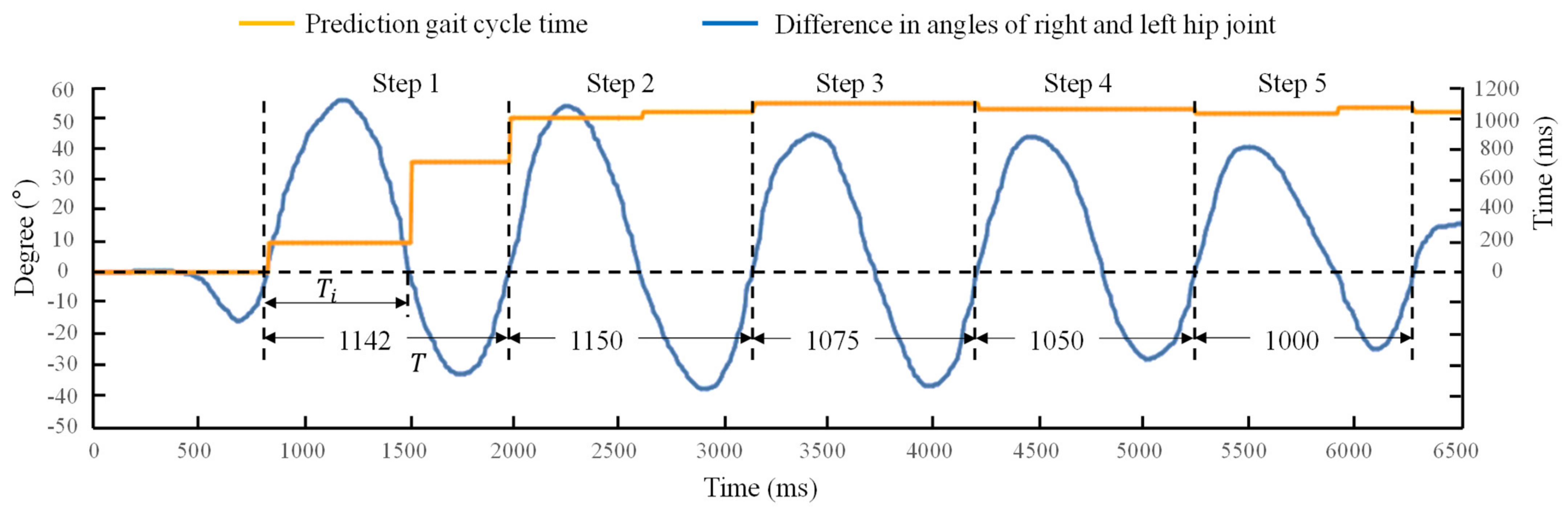
2.3. Gait Cycle Time Prediction
2.4. Control Strategy of the Active Hip Extension Assistance
2.5. Materials and Methods for Assistance Force Evaluation
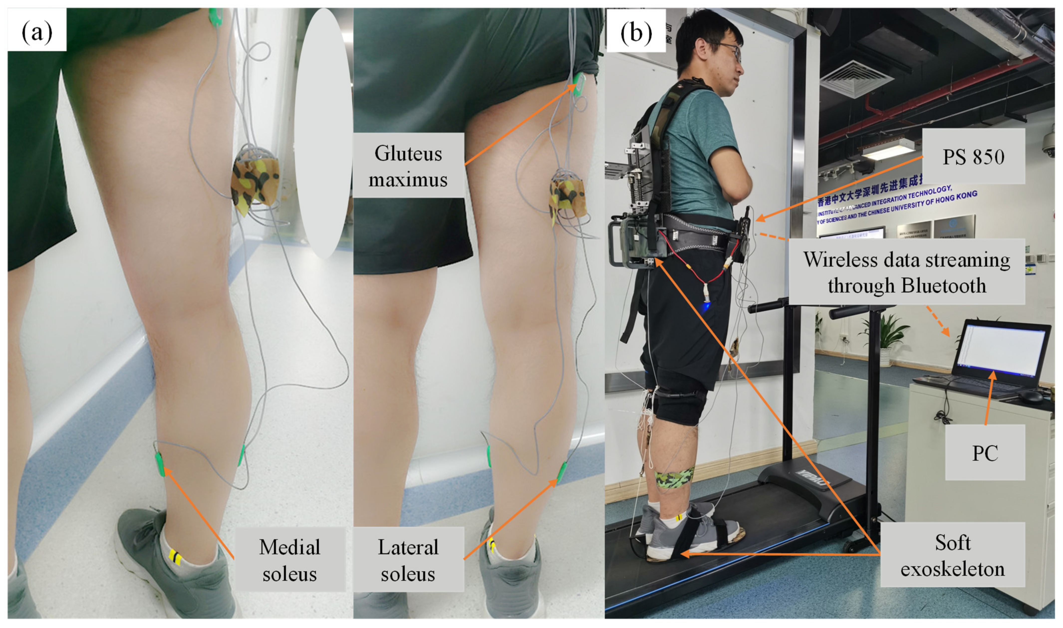
2.6. Materials and Methods for Muscle Activity Evaluation
2.7. Materials and Methods for Metabolic Cost Evaluation
3. Results
3.1. The Determination of Assistance Strategy
3.2. Test of the Gait Cycle Length Prediction Method
3.3. Assistance Force Evaluation
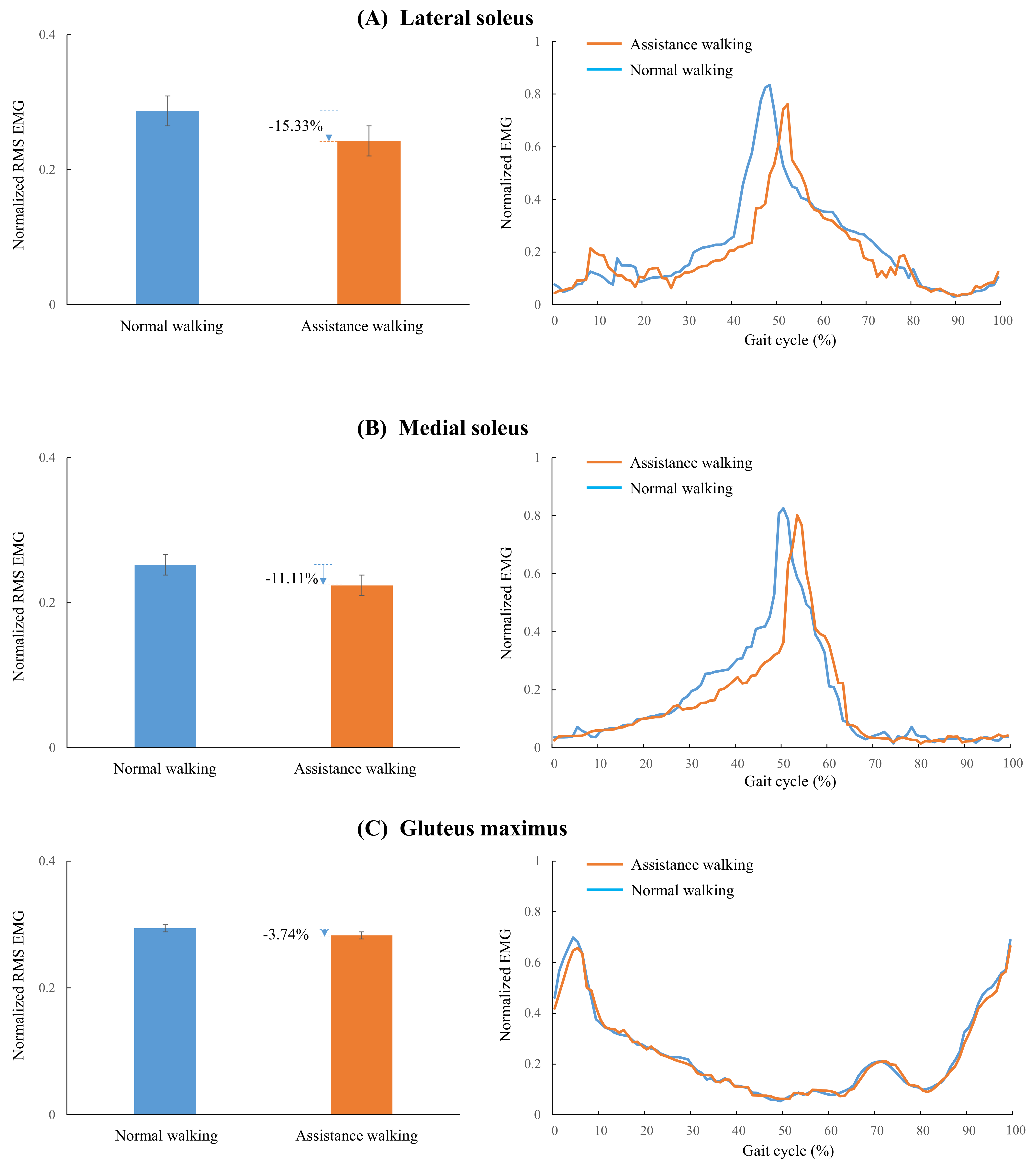
3.4. Muscle Activity Evaluation
3.5. Metabolic Cost Evaluation
4. Discussion
4.1. Design Features
4.2. Muscle Activity
4.3. Metabolic Cost
4.4. Active Control Strategy
4.5. Limitations of This Work
5. Conclusions
Author Contributions
Funding
Institutional Review Board Statement
Informed Consent Statement
Data Availability Statement
Conflicts of Interest
References
- Cao, W.; Chen, C.; Hu, H.; Fang, K.; Wu, X. Effect of hip assistance modes on metabolic cost of walking with a soft exoskeleton. IEEE Trans. Autom. Sci. Eng. 2020, 18, 426–436. [Google Scholar] [CrossRef]
- Yang, Y.; Ma, L.; Huang, D. Development and repetitive learning control of lower limb exoskeleton driven by electrohydraulic actuators. IEEE Trans. Ind. Electron. 2016, 64, 4169–4178. [Google Scholar] [CrossRef]
- Yuan, Y.; Li, Z.; Zhao, T.; Gan, D. DMP-based motion generation for a walking exoskeleton robot using reinforcement learning. IEEE Trans. Ind. Electron. 2019, 67, 3830–3839. [Google Scholar] [CrossRef]
- Wei, Q.; Li, Z.; Zhao, K.; Kang, Y.; Su, C.-Y. Synergy-based control of assistive lower-limb exoskeletons by skill transfer. IEEE Trans. Mechatron. 2020, 25, 705–715. [Google Scholar] [CrossRef]
- Wang, J.; Fei, Y.; Chen, W. Integration, sensing, and control of a modular soft-rigid pneumatic lower limb exoskeleton. Soft Robot. 2020, 7, 140–154. [Google Scholar] [CrossRef] [PubMed]
- Ma, Y.; Wu, X.; Yi, J.; Wang, C.; Chen, C. A review on human-exoskeleton coordination towards lower limb robotic exoskeleton systems. Int. J. Robot. Autom. 2019, 34, 4. [Google Scholar] [CrossRef] [Green Version]
- Ma, Y.; Wu, X.; Yang, S.X.; Dang, C.; Liu, D.-X.; Wang, C.; Chen, C. Online gait planning of lower-limb exoskeleton robot for paraplegic rehabilitation considering weight transfer process. IEEE Trans. Autom. Sci. Eng. 2020, 18, 414–425. [Google Scholar] [CrossRef]
- Huang, R.; Cheng, H.; Qiu, J.; Zhang, J. Learning physical human-robot interaction with coupled cooperative primitives for a lower exoskeleton. IEEE Trans. Autom. Sci. Eng. 2019, 16, 1566–1574. [Google Scholar] [CrossRef]
- Bougrinat, Y.; Achiche, S.; Raison, M. Design and development of a lightweight ankle exoskeleton for human walking augmentation. Mechatronics 2019, 64, 102297. [Google Scholar] [CrossRef] [Green Version]
- Panizzolo, F.A.; Bolgiani, C.; Di Liddo, L.; Annese, E.; Marcolin, G. Reducing the energy cost of walking in older adults using a passive hip flexion device. J. Neuroeng. Rehabil. 2019, 16, 117. [Google Scholar] [CrossRef] [Green Version]
- Ding, Y.; Galiana, I.; Asbeck, A.; De Rossi, S.M.M.; Bae, J.; Santos, T.R.T.; De Araujo, V.L.; Lee, S.; Holt, K.G.; Walsh, C. Biomechanical and physiological evaluation of multi-joint assistance with soft exosuits. IEEE Trans. Neural Syst. Rehabil. Eng. 2016, 25, 119–130. [Google Scholar] [CrossRef] [PubMed]
- Mooney, L.M.; Rouse, E.J.; Herr, H.M. Autonomous exoskeleton reduces metabolic cost of human walking during load carriage. J. Neuroeng. Rehabil. 2014, 11, 80. [Google Scholar] [CrossRef] [PubMed] [Green Version]
- Jackson, R.W.; Collins, S.H. An experimental comparison of the relative benefits of work and torque assistance in ankle exoskeletons. J. Appl. Physiol. 2015, 119, 541–557. [Google Scholar] [CrossRef] [PubMed] [Green Version]
- Zhang, J.; Fiers, P.; Witte, K.A.; Jackson, R.W.; Poggensee, K.L.; Atkeson, C.G.; Collins, S.H. Human-in-the-loop optimization of exoskeleton assistance during walking. Science 2017, 356, 1280–1284. [Google Scholar] [CrossRef] [Green Version]
- Wang, W.; Chen, J.; Ji, Y.; Jin, W.; Liu, J.; Zhang, J. Evaluation of lower leg muscle activities during human walking assisted by an ankle exoskeleton. IEEE Trans. Ind. Inform. 2020, 16, 7168–7176. [Google Scholar] [CrossRef]
- MacLean, M.K.; Ferris, D.P. Energetics of walking with a robotic knee exoskeleton. J. Appl. Biomech. 2019, 35, 320–326. [Google Scholar] [CrossRef] [Green Version]
- Kim, J.; Lee, G.; Heimgartner, R.; Revi, D.A.; Karavas, N.; Nathanson, D.; Galiana, I.; Eckert-Erdheim, A.; Murphy, P.; Perry, D.; et al. Reducing the metabolic rate of walking and running with a versatile, portable exosuit. Science 2019, 365, 668–672. [Google Scholar] [CrossRef] [PubMed]
- Quinlivan, B.T.; Lee, S.; Malcolm, P.; Rossi, D.M.; Grimmer, M.; Siviy, C.; Karavas, N.; Wagner, D.; Asbeck, A.; Galiana, I.; et al. Assistance magnitude versus metabolic cost reductions for a tethered multiarticular soft exosuit. Sci. Robot. 2017, 2, eaah4416. [Google Scholar] [CrossRef]
- Lee, S.; Kim, J.; Baker, L.; Long, A.; Karavas, N.; Menard, N.; Galiana, I.; Walsh, C.J. Autonomous multi-joint soft exosuit with augmentation-power-based control parameter tuning reduces energy cost of loaded walking. J. Neuroeng. Rehabil. 2018, 15, 66. [Google Scholar] [CrossRef]
- Wu, X.; Fang, K.; Chen, C.; Zhang, Y. Development of a lower limb multi-joint assistance soft exosuit. Sci. China Inf. Sci. 2020, 63, 170207. [Google Scholar] [CrossRef]
- Collins, S.H.; Wiggin, M.B.; Sawicki, G.S. Reducing the energy cost of human walking using an unpowered exoskeleton. Nature 2015, 522, 212–215. [Google Scholar] [CrossRef] [Green Version]
- Yandell, M.B.; Tacca, J.R.; Zelik, K.E. Design of a low profile, unpowered ankle exoskeleton that fits under clothes: Overcoming practical barriers to widespread societal adoption. IEEE Trans. Neural Syst. Rehabil. Eng. 2019, 27, 712–723. [Google Scholar] [CrossRef]
- Nasiri, R.; Ahmadi, A.; Ahmadabadi, M.N. Reducing the energy cost of human running using an unpowered exoskeleton. IEEE Trans. Neural Syst. Rehabil. Eng. 2018, 26, 2026–2032. [Google Scholar] [CrossRef]
- Simpson, C.S.; Welker, C.G.; Uhlrich, S.D.; Sketch, S.M.; Jackson, R.W.; Delp, S.L.; Collins, S.H.; Selinger, J.C.; Hawkes, E.W. Connecting the legs with a spring improves human running economy. J. Exp. Biol. 2019, 222, jeb202895. [Google Scholar] [CrossRef] [Green Version]
- Chen, C.; Zhang, Y.; Li, Y.; Wang, Z.; Liu, Y.; Cao, W.; Wu, X. Iterative learning control for a soft exoskeleton with hip and knee joint assistance. Sensors 2020, 20, 4333. [Google Scholar] [CrossRef] [PubMed]
- Lee, G.; Ding, Y.; Bujanda, I.G.; Karavas, N.; Zhou, Y.M.; Walsh, C.J. Improved assistive profile tracking of soft exosuits for walking and jogging with off-board actuation. In Proceedings of the IEEE/RSJ International Conference on Intelligent Robots and Systems (IROS), Vancouver, BC, Canada, 24–28 September 2017; pp. 1699–1706. [Google Scholar]
- Browning, R.C.; Modica, J.R.; Kram, R.; Goswami, A. The effects of adding mass to the legs on the energetics and biomechanics of walking. Med. Sci. Sports Exerc. 2007, 39, 515–525. [Google Scholar] [CrossRef] [PubMed] [Green Version]
- Grabowski, A.; Farley, C.T.; Kram, R. Independent metabolic costs of supporting body weight and accelerating body mass during walking. J. Appl. Physiol. 2005, 98, 579–583. [Google Scholar] [CrossRef] [PubMed] [Green Version]
- Ding, Y.; Galiana, I.; Asbeck, A.; Quinlivan, B.; De Rossi, S.M.M.; Walsh, C. Multi-joint actuation platform for lower extremity soft exosuits. In Proceedings of the IEEE International Conference on Robotics and Automation, Hong Kong, China, 31 May–7 June 2014; pp. 1327–1334. [Google Scholar]
- Ding, Y.; Kim, M.; Kuindersma, S.; Walsh, C.J. Human-in-the-loop optimization of hip assistance with a soft exosuit during walking. Sci. Robot. 2018, 3, eaar5438. [Google Scholar] [CrossRef] [PubMed] [Green Version]
- Ding, Y.; Galiana, I.; Siviy, C.; Panizzolo, F.A.; Walsh, C. IMU-based iterative control for hip extension assistance with a soft exosuit. In Proceedings of the IEEE International Conference on Robotics and Automation (ICRA), Stockholm, Sweden, 16–21 May 2016; pp. 3501–3508. [Google Scholar]


| Subject | Net Metabolic Rate (W/kg) | |
|---|---|---|
| NE | EO | |
| 1 | 3.788 | 3.298 |
| 2 | 3.720 | 3.481 |
| 3 | 3.706 | 3.184 |
| 4 | 3.817 | 3.381 |
| 5 | 3.742 | 3.441 |
| 6 | 3.596 | 3.254 |
| Mean SEM | 3.728 0.031 | 3.340 0.047 |
| Research | Weight (kg) | Net Metabolic Cost Reduction (%) | Average Muscle Activities Reduction (%) | |
|---|---|---|---|---|
| Sum of Soleus | Gluteus Maximus | |||
| Panizzolo et al. [10] | 0.645 | 3.33.0 | \ | \ |
| Mooney et al. [12] | 4 | 8 | \ | \ |
| MacLean et al. [16] | 8.4 | 4.2 | \ | \ |
| Kim et al. [17] | 5.004 | 9.3 | \ | 2.66 |
| This work | 3.5 | 10.41 | 26.44 | 3.74 |
| Collins et al. [21] | 0.816–1.006 | 7.22.6 | 22 | \ |
| Yandell et al. [22] | 0.459 | \ | 10 | \ |
Publisher’s Note: MDPI stays neutral with regard to jurisdictional claims in published maps and institutional affiliations. |
© 2021 by the authors. Licensee MDPI, Basel, Switzerland. This article is an open access article distributed under the terms and conditions of the Creative Commons Attribution (CC BY) license (https://creativecommons.org/licenses/by/4.0/).
Share and Cite
Cao, W.; Zhang, Z.; Chen, C.; He, Y.; Wang, D.; Wu, X. Biomechanical and Physiological Evaluation of a Multi-Joint Exoskeleton with Active-Passive Assistance for Walking. Biosensors 2021, 11, 393. https://doi.org/10.3390/bios11100393
Cao W, Zhang Z, Chen C, He Y, Wang D, Wu X. Biomechanical and Physiological Evaluation of a Multi-Joint Exoskeleton with Active-Passive Assistance for Walking. Biosensors. 2021; 11(10):393. https://doi.org/10.3390/bios11100393
Chicago/Turabian StyleCao, Wujing, Zhewen Zhang, Chunjie Chen, Yong He, Dashuai Wang, and Xinyu Wu. 2021. "Biomechanical and Physiological Evaluation of a Multi-Joint Exoskeleton with Active-Passive Assistance for Walking" Biosensors 11, no. 10: 393. https://doi.org/10.3390/bios11100393
APA StyleCao, W., Zhang, Z., Chen, C., He, Y., Wang, D., & Wu, X. (2021). Biomechanical and Physiological Evaluation of a Multi-Joint Exoskeleton with Active-Passive Assistance for Walking. Biosensors, 11(10), 393. https://doi.org/10.3390/bios11100393