Electrical Properties and Electromagnetic Interference Shielding Effectiveness of Interlayered Systems Composed by Carbon Nanotube Filled Carbon Nanofiber Mats and Polymer Composites

 ,
, 
Abstract
:
1. Introduction
2. Materials and Methods
2.1. Materials
2.2. Production of MWCNT Filled Carbon Nanofiber Mats Using the Forcespinning® Method
2.3. Preparation of Nanoreinforced Polymer Composite Sheets (NRPCS)
2.4. Fabrication of Interlayered Composites (IC)
2.5. Characterization
3. Results
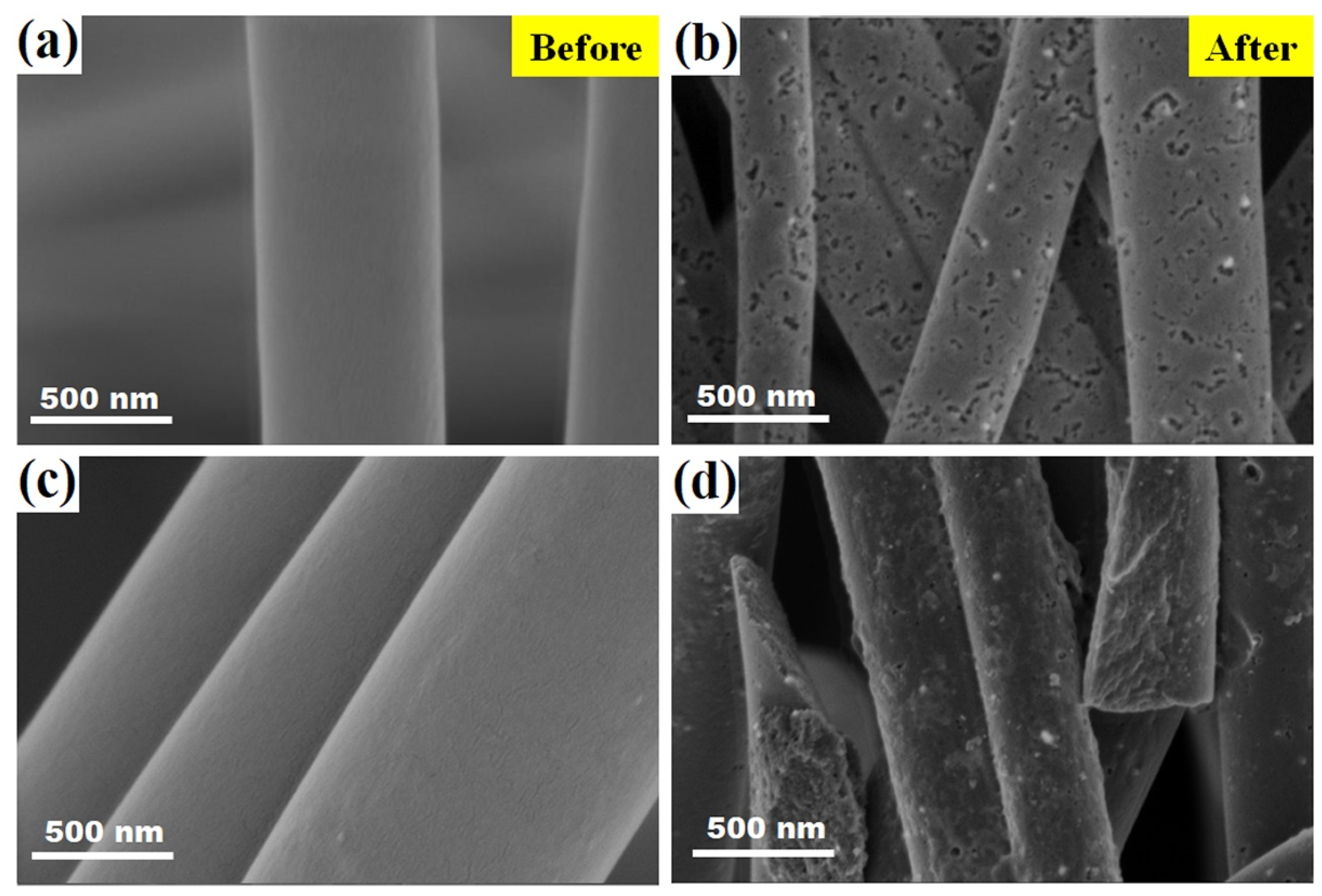
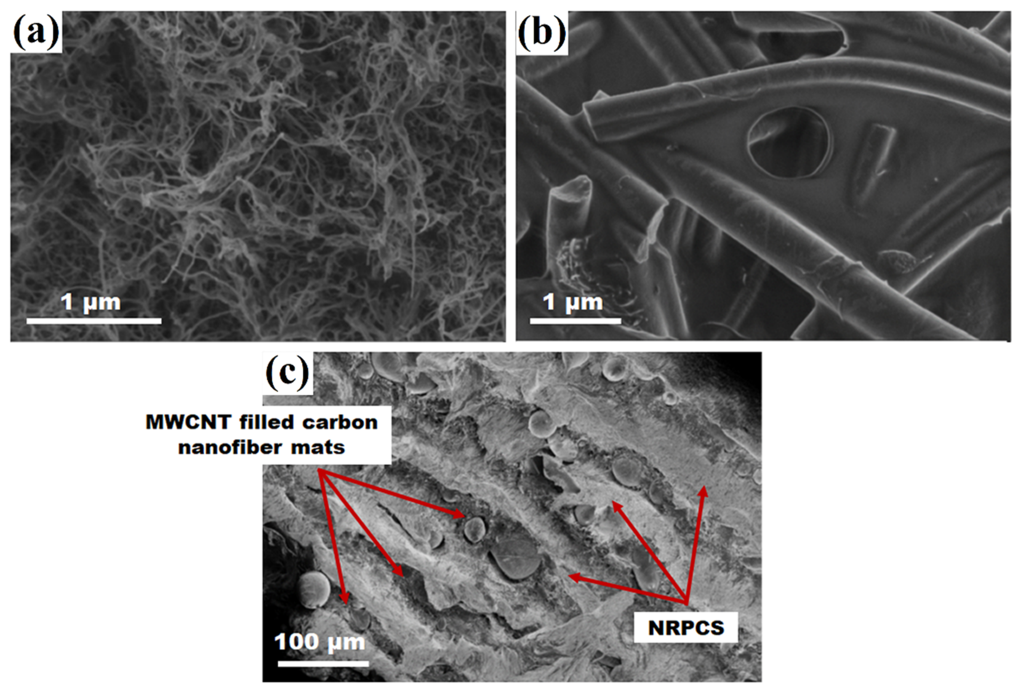
3.1. Morphological Analysis of Nonwoven Fiber Mats, MWCNT-Carbon Nanofiber Composite Mats, and Interlayered Composites
3.2. Electrical Properties of MWCNT Filled Carbon Nanofiber Mat and Interlayered Composites
3.3. EMI Shielding Effectiveness
4. Discussion
5. Conclusions
Author Contributions
Funding
Conflicts of Interest
References
- Njuguna, J.; Pielichowski, K.; Fan, J. Polymer nanocomposites for aerospace applications. In Advances in Polymer Nanocomposites: Types and Applications, 1st ed.; Gao, F., Ed.; Woodhead Publishing Limited: Cambridge, UK, 2012; pp. 472–539. [Google Scholar]
- Müller, K.; Bugnicourt, E.; Latorre, M.; Jorda, M.; Echegoyen Sanz, Y.; Lagaron, J.M.; Miesbauer, O.; Bianchin, A.; Hankin, S.; Bölz, U.; et al. Review on the processing and properties of polymer nanocomposites and nanocoatings and their applications in the packaging, automotive and solar energy fields. Nanomaterials 2017, 7, 74. [Google Scholar] [CrossRef] [PubMed]
- Mittal, G.; Rhee, K.Y.; Mišković-Stanković, V.; Hui, D. Reinforcements in multi-scale polymer composites: Processing, properties, and applications. Compos. Part B 2017, 138, 122–139. [Google Scholar] [CrossRef]
- Chung, D.D.L. Electromagnetic interference shielding effectiveness of carbon materials. Carbon 2001, 39, 279–285. [Google Scholar] [CrossRef]
- Moniruzzaman, M.; Winey, K.I. Polymer nanocomposites containing carbon nanotubes. Macromolecules 2006, 39, 5194–5205. [Google Scholar] [CrossRef]
- Spitalsky, Z.; Tasis, D.; Papagelis, K.; Galiotis, C. Carbon nanotube-polymer composites: chemistry, processing, mechanical and electrical properties. Prog. Polym. Sci. 2010, 35, 357–401. [Google Scholar] [CrossRef]
- Mittal, G.; Dhand, V.; Rhee, K.Y.; Park, S.-J.; Lee, W.R. A review on carbon nanotubes and graphene as fillers in reinforced polymer nanocomposites. J. Ind. Eng. Chem. 2015, 21, 11–25. [Google Scholar] [CrossRef]
- Al-Saleh, M.H.; Sundararaj, U. A review of vapor grown carbon nanofiber/polymer conductive composites. Carbon 2009, 47, 2–22. [Google Scholar] [CrossRef]
- Tibbetts, G.G.; Lake, M.L.; Strong, K.L.; Rice, B.P. A review of the fabrication and properties of vapor-grown carbon nanofiber/polymer composites. Compos. Sci. Technol. 2007, 67, 1709–1718. [Google Scholar] [CrossRef]
- Das, T.K.; Prusty, S. Graphene-based polymer composites and their applications. Polym. Plast. Technol. Eng. 2013, 52, 319–331. [Google Scholar] [CrossRef]
- Papageorgiou, D.G.; Kinloch, I.A.; Young, R.J. Mechanical properties of graphene and graphene-based nanocomposites. Prog. Mater. Sci. 2017, 90, 75–127. [Google Scholar] [CrossRef]
- Pandey, G.; Thostenson, E.T. Carbon nanotube-based multifunctional polymer nanocomposites. Polym. Rev. 2012, 52, 355–416. [Google Scholar] [CrossRef]
- Lake, C.L.; Lake, P.D. Carbon nanofiber multifunctional mat. In Nanotube Superfiber Materials-Changing Engineering Design, 1st ed.; Schulz, M.J., Shanov, V.N., Yin, Z., Eds.; William Andrew: Oxford, UK, 2014; pp. 313–331. [Google Scholar]
- Zucchelli, A.; Focarete, M.L.; Gualandi, C.; Ramakrishna, S. Electrospun nanofibers for enhancing structural performance of composite materials. Polym. Adv. Technol. 2011, 22, 339–349. [Google Scholar] [CrossRef]
- Qian, H.; Greenhalgh, E.S.; Shaffer, M.S.P.; Bismarck, A. Carbon nanotube-based hierarchical composites: A review. J. Mater. Chem. 2010, 20, 4751–4762. [Google Scholar] [CrossRef]
- Aluko, O.; Gowtham, S.; Odegard, G.M. Multiscale modeling and analysis of graphene nanoplatelet/carbon fiber/epoxy hybrid composite. Compos. Part B 2017, 131, 82–90. [Google Scholar] [CrossRef]
- Xu, H.; Tong, X.; Zhang, Y.; Li, Q.; Lu, W. Mechanical and electrical properties of laminated composites containing continuous carbon nanotube film interleaves. Compos. Sci. Technol. 2016, 127, 113–118. [Google Scholar] [CrossRef]
- Wang, S.; Downes, R.; Young, C.; Haldane, D.; Hao, A.; Liang, R.; Wang, B.; Zhang, C.; Maskell, R. Carbon fiber/carbon nanotube buckypaper interply hybrid composites: Manufacturing process and tensile properties. Adv. Eng. Mater. 2015, 17, 1442–1453. [Google Scholar] [CrossRef]
- Su, Y.; Zhang, S.; Zhang, X.; Zhao, Z.; Jing, D. Preparation and properties of carbon nanotubes/carbon fiber/poly (ether ketone) multiscale composites. Compos. Part A 2018, 108, 89–98. [Google Scholar] [CrossRef]
- Veedu, V.P.; Cao, A.; Li, X.; Ma, K.; Soldano, C.; Kar, S.; Ajayan, P.M.; Ghasemi-Nejhad, M.N. Multifunctional composites using reinforced laminae with carbon-nanotube forests. Nat. Mater. 2006, 5, 457–462. [Google Scholar] [CrossRef]
- Zhou, H.W.; Mishnaevsky, L., Jr.; Yi, H.Y.; Liu, Y.Q.; Hu, X.; Warrier, A.; Dai, G.M. Carbon fiber/carbon nanotube reinforced hierarchical composites: Effect of CNT distribution on shearing strength. Compos. Part B 2016, 88, 201–211. [Google Scholar] [CrossRef]
- Shin, Y.C.; Novin, E.; Kim, H. Electrical and thermal conductivities of carbon fiber composites with high concentrations of carbon nanotubes. Int. J. Precis. Eng. Manuf. 2015, 16, 465–470. [Google Scholar] [CrossRef]
- Park, J.G.; Louis, J.; Cheng, Q.; Bao, J.; Smithyman, J.; Liang, R.; Wang, B.; Zhang, C.; Brooks, J.S.; Kramer, L.; et al. Electromagnetic interference shielding properties of carbon nanotube buckypaper composites. Nanotechnology 2009, 20, 415702. [Google Scholar] [CrossRef] [PubMed]
- Silveira, D.C.; Gomes, N.; Rezende, M.C.; Botelho, E.C. Electromagnetic properties of multifunctional composites based on glass fiber prepreg and Ni/carbon fiber veil. J. Aerosp. Technol. Manag. 2017, 9, 231–240. [Google Scholar] [CrossRef]
- Zhao, X.; Fu, J.; Wang, H. The electromagnetic interference shielding performance of continuous carbon fiber composites with different arrangements. J. Ind. Text. 2016, 46, 45–58. [Google Scholar] [CrossRef]
- Sarkar, K.; Gomez, C.; Zambrano, S.; Ramirez, M.; de Hoyos, E.; Vasquez, H.; Lozano, K. Electrospinning to ForcespinningTM. Mater. Today 2010, 13, 12–14. [Google Scholar] [CrossRef]
- Akia, M.; Cremar, L.; Chipara, M.; Munoz, E.; Cortez, H.; de Santiago, H.; Rodriguez-Macias, F.J.; Vega-Cantú, Y.I.; Arandiyan, H.; Sun, H.; et al. In situ production of graphene-fiber hybrid structures. ACS Appl. Mater. Interfaces 2017, 9, 25474–25480. [Google Scholar] [CrossRef]
- Cremar, L.D.; Acosta-Martinez, J.; Villarreal, A.; Salinas, A.; Wei, L.; Mao, Y.; Lozano, K. High-throughput of multifunctional carbon nanofibers from water soluble precursors. Chem. Fibers Int. 2016, 66, 40–42. [Google Scholar]
- Vasquez, H.; Espinoza, L.; Lozano, K.; Foltz, H.; Yang, S. Simple device for electromagnetic interference shielding effectiveness measurement. IEEE EMC Soc. Newslett. 2009, 220, 62–68. [Google Scholar]
- Al-Saleh, M.H.; Sundararaj, U. Electromagnetic interference shielding mechanisms of CNT/polymer composites. Carbon 2009, 47, 1738–1746. [Google Scholar] [CrossRef]
- Al-Saleh, M.H.; Saadeh, W.H.; Sundararaj, U. EMI shielding effectiveness of carbon based nanostructured polymeric materials: A comparative study. Carbon 2013, 60, 146–156. [Google Scholar] [CrossRef]
- Song, W.-L.; Cao, M.-S.; Lu, M.-M.; Bi, S.; Wang, C.-Y.; Liu, J.; Yuan, J.; Fan, L.-Z. Flexible graphene/polymer composite films in sandwich structures for effective electromagnetic interference shielding. Carbon 2014, 66, 67–76. [Google Scholar] [CrossRef]
- Farukh, M.; Singh, A.P.; Dhawan, S.K. Enhanced electromagnetic shielding behavior of multi-walled carbon nanotube entrenched poly (3,4-ethylenedioxythiophene) nanocomposites. Compos. Sci. Technol. 2015, 114, 94–102. [Google Scholar] [CrossRef]
- Lee, S.-H.; Kang, D.; Oh, I.-K. Multilayered graphene-carbon nanotube-iron oxide three-dimensional heterostructure for flexible electromagnetic interference shielding film. Carbon 2017, 111, 248–257. [Google Scholar] [CrossRef]
- Cremar, L.D.; Acosta-Martinez, J.; Villarreal, A.; Salinas, A.; Lozano, K. Mechanical and electrical characterization of carbon nanofibers produced from water soluble precursors. Mater. Today Commun. 2016, 7, 134–139. [Google Scholar] [CrossRef]
- Chung, D.D.L. Materials for electromagnetic interference shielding. J. Mater. Eng. Perform. 2000, 9, 350–354. [Google Scholar] [CrossRef]
- Gelves, G.A.; Al-Saleh, M.H.; Sundararaj, U. Highly electrically conductive and high performance EMI shielding nanowire/polymer nanocomposites by miscible mixing and precipitation. J. Mater. Chem. 2011, 21, 829–836. [Google Scholar] [CrossRef]
- Ra, E.J.; An, K.H.; Kim, K.K.; Jeong, S.Y.; Lee, Y.H. Anisotropic electrical conductivity of MWCNT/PAN nanofiber paper. Chem. Phys. Lett. 2005, 413, 188–193. [Google Scholar] [CrossRef]
- Arjmand, M.; Mahmoodi, M.; Gelves, G.A.; Park, S.; Sundararaj, U. Electrical and electromagnetic interference shielding properties of flow-induced oriented carbon nanotubes in polycarbonate. Carbon 2011, 49, 3430–3440. [Google Scholar] [CrossRef]
- Chen, Z.; Xu, C.; Ma, C.; Ren, W.; Cheng, H.-M. Lightweight and flexible graphene foam composites for high-performance electromagnetic interference shielding. Adv. Mater. 2013, 25, 1296–1300. [Google Scholar] [CrossRef]
- Zeng, Z.; Jin, H.; Chen, M.; Li, W.; Zhou, L.; Zhang, Z. Lightweight and anisotropic porous MWCNT/WPU composites for ultrahigh performance electromagnetic interference shielding. Adv. Funct. Mater. 2016, 26, 303–310. [Google Scholar] [CrossRef]
- Ameli, A.; Nofar, M.; Wang, S.; Park, C.B. Lightweight polypropylene/stainless-steel fiber composite foams with low percolation for efficient electromagnetic interference shielding. ACS Appl. Mater. Interfaces 2014, 6, 11091–11100. [Google Scholar] [CrossRef]
- Raagulan, K.; Braveenth, R.; Jang, H.J.; Lee, Y.S.; Yang, C.-M.; Kim, B.M.; Moon, J.J.; Chai, K.Y. Electromagnetic shielding by MXene-graphene-PVDF composite with hydrophobic, lightweight and flexible graphene coated fabric. Materials 2018, 11, 1803. [Google Scholar] [CrossRef]
- King, J.A.; Pisani, W.A.; Klimek-McDonald, D.R.; Perger, W.F.; Odegard, G.M.; Turpeinen, D.G. Shielding effectiveness of carbon-filled polypropylene composites. J. Compos. Mater. 2016, 50, 2177–2189. [Google Scholar] [CrossRef]
- Schulz, R.B.; Plantz, V.C.; Brush, D.R. Shielding theory and practice. IEEE Trans. Electromagn. Compat. 1988, 30, 187–201. [Google Scholar] [CrossRef]
- Guo, Q.; Zhou, X.; Li, X.; Chen, S.; Seema, A.; Greiner, A.; Hou, H. Supercapacitors based on hybrid carbon nanofibers containing multiwalled carbon nanotubes. J. Mater. Chem. 2009, 19, 2810–2816. [Google Scholar] [CrossRef]
- Engel, A.B.; Cherifi, A.; Tingry, S.; Cornu, D.; Peigney, A.; Laurent, C. Enhanced performance of electrospun carbon fibers modified with carbon nanotubes: promising electrodes for enzymatic biofuel cells. Nanotechnology 2013, 24, 245402. [Google Scholar] [CrossRef]
- Weng, B.; Xu, F.; Salinas, A.; Lozano, K. Mass production of carbon nanotube reinforced poly(methyl methacrylate) nonwoven nanofiber mats. Carbon 2014, 75, 217–226. [Google Scholar] [CrossRef]
- Chang, H.; Yeh, Y.-M.; Huang, K.-D. Electromagnetic shielding by composite films prepared with carbon fiber, Ni nanoparticles, and multi-walled carbon nanotubes in polyurethane. Mater. Trans. 2010, 51, 1145–1149. [Google Scholar] [CrossRef]
- Jou, W.-S.; Cheng, H.-Z.; Hsu, C.-F. The electromagnetic shielding effectiveness of carbon nanotubes polymer composites. J. Alloys Compd. 2007, 434–435, 641–645. [Google Scholar] [CrossRef]
- Luo, X.; Chung, D.D.L. Electromagnetic interference shielding reaching 130 dB using flexible graphite. Mat. Res. Soc. Symp. Proc. 1997, 445, 235–238. [Google Scholar] [CrossRef]
- Luo, X.; Chung, D.D.L. Electromagnetic interference shielding using continuous carbon-fiber carbon-matrix and polymer-matrix composites. Compos. Part B 1999, 30, 227–231. [Google Scholar] [CrossRef]
- Das, N.C.; Khastgir, D.; Chaki, T.K.; Chakraborty, A. Electromagnetic interference shielding effectiveness of carbon black and carbon fibre filled EVA and NR based composites. Compos. Part A 2000, 31, 1069–1081. [Google Scholar] [CrossRef]
- Yang, S.; Lozano, K.; Lomeli, A.; Foltz, H.D.; Jones, R. Electromagnetic interference shielding effectiveness of carbon nanofiber/LCP composites. Compos. Part A 2005, 36, 691–697. [Google Scholar] [CrossRef]
- Thomassin, J.-M.; Pagnoulle, C.; Bednarz, L.; Huynen, I.; Jerome, R.; Detrembleur, C. Foams of polycaprolactone/MWNT nanocomposites for efficient EMI reduction. J. Mater. Chem. 2008, 18, 792–796. [Google Scholar] [CrossRef]
- Mahmoodi, M.; Arjmand, M.; Sundararaj, U.; Park, S. The electrical conductivity and electromagnetic interference shielding of injection molded multi-walled carbon nanotube/polystyrene composites. Carbon 2012, 50, 1455–1464. [Google Scholar] [CrossRef]

 ), transmittance (
  ), and absorbance (
  ) of the interlayered composites: (a) IC-1-0.1; (b) IC-4-0.1; and, (c) IC-8-0.1.
), transmittance ( ), and absorbance ( ) of the interlayered composites: (a) IC-1-0.1; (b) IC-4-0.1; and, (c) IC-8-0.1.
) of the interlayered composites: (a) IC-1-0.1; (b) IC-4-0.1; and, (c) IC-8-0.1.
), transmittance ( ), and absorbance ( ) of the interlayered composites: (a) IC-1-0.1; (b) IC-4-0.1; and, (c) IC-8-0.1.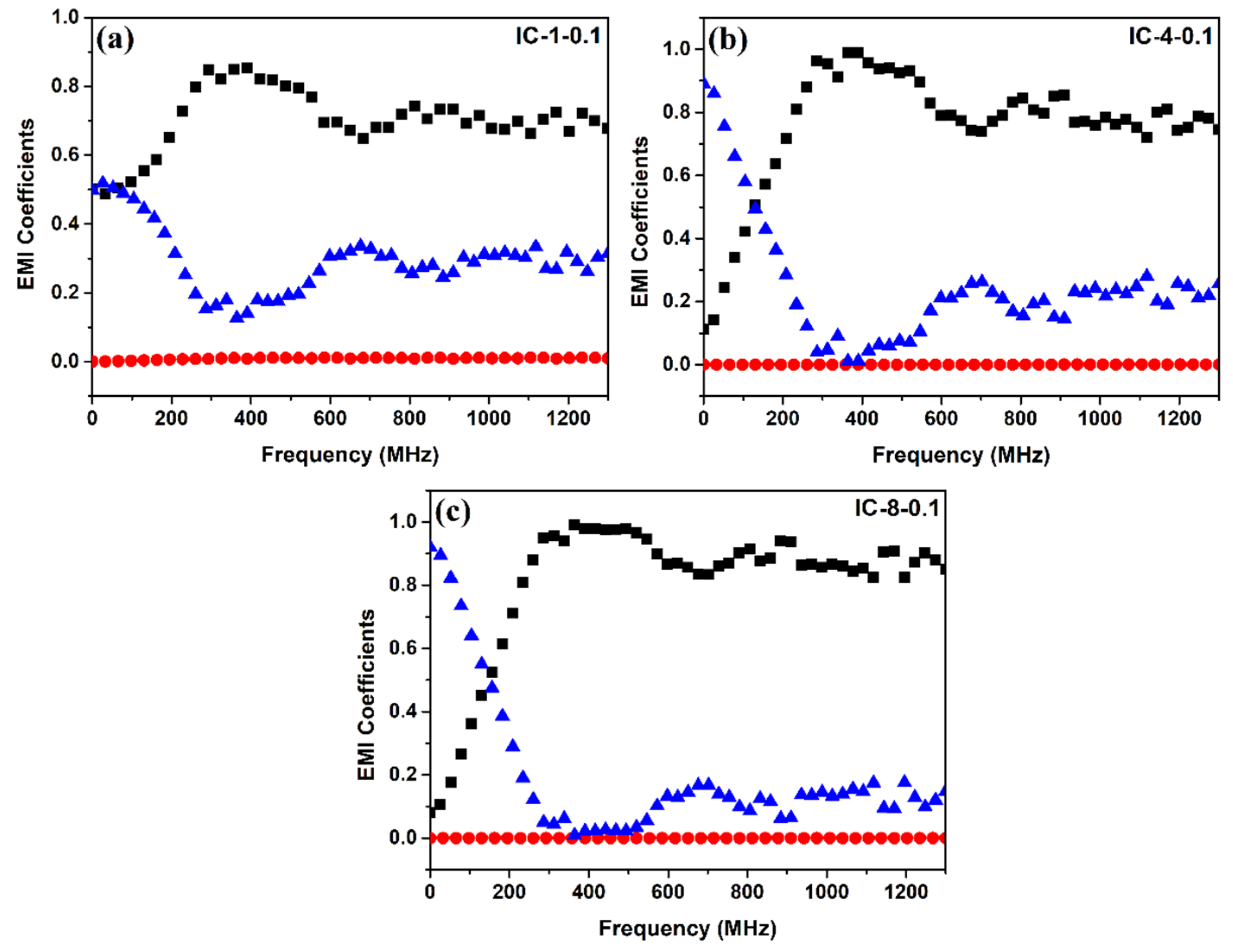
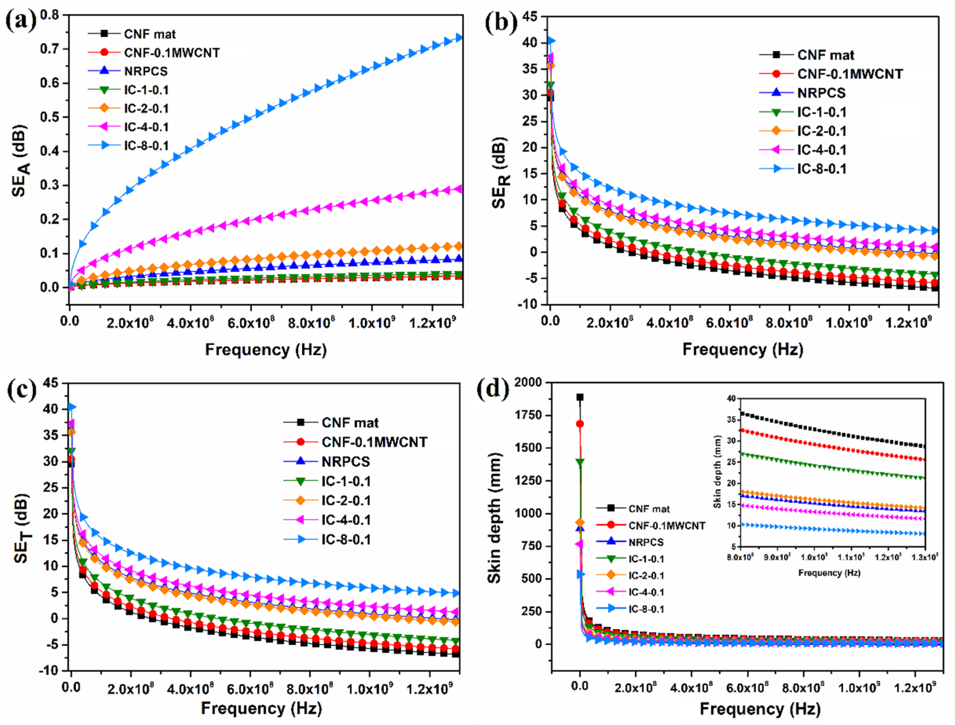
 ), absorption, SEabs (
  ), and total SE, SETotal (
  ) for interlayered composites: (a) IC-1-0.1; (b) IC-4-0.1; and, (c) IC-8-0.1.
), absorption, SEabs ( ), and total SE, SETotal ( ) for interlayered composites: (a) IC-1-0.1; (b) IC-4-0.1; and, (c) IC-8-0.1.
) for interlayered composites: (a) IC-1-0.1; (b) IC-4-0.1; and, (c) IC-8-0.1.
), absorption, SEabs ( ), and total SE, SETotal ( ) for interlayered composites: (a) IC-1-0.1; (b) IC-4-0.1; and, (c) IC-8-0.1.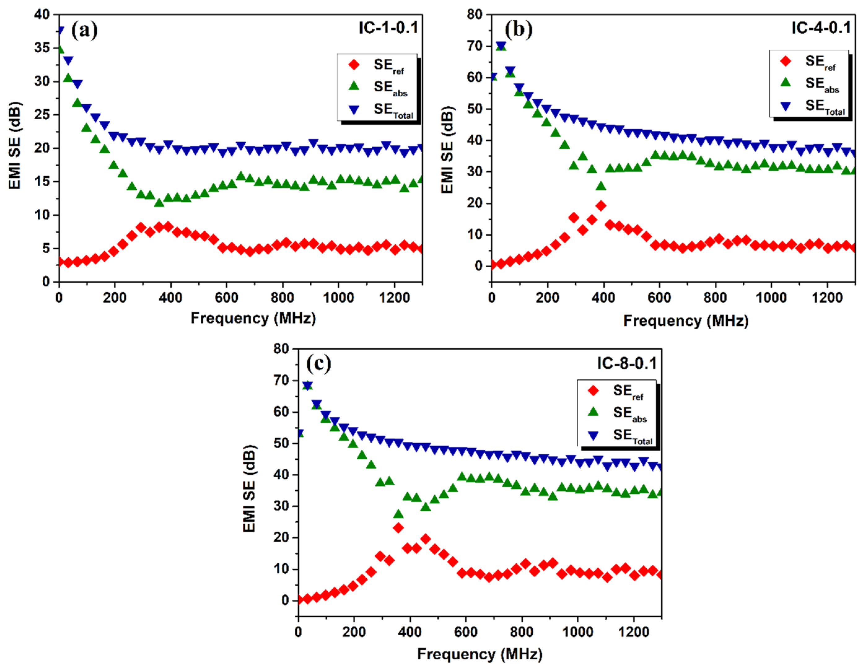

| ID Sample | CNF Mat | CNF–0.05MWCNT | CNF–0.1MWCNT | NRPCS | IC–1–0 2,3 | IC–1–0.05 | IC–1–0.1 | IC–2–0.1 | IC–4–0.1 | IC–8–0.1 |
|---|---|---|---|---|---|---|---|---|---|---|
| Parameter | ||||||||||
| Thickness (mm) | 0.11 | 0.09 | 0.09 | 0.13 | 0.10 | 0.10 | 0.10 | 0.16 | 0.30 | 0.65 |
| Density (g·cm−3) | 0.33 | 0.30 | 0.28 | 0.99 | 0.79 | 0.79 | 0.78 | 0.73 | 0.70 | 0.68 |
| CNF (wt.%) | 100 | 99.9 | 99.9 | – | 12.5 | 11.2 | 10.6 | 13.9 | 16.2 | 17.7 |
| CNF (vol.%) | 100 | 99.9 | 99.9 | – | 29.8 | 29.5 | 29.6 | 36.4 | 40.7 | 43.3 |
| MWCNT in CNF (wt.%) | – | 0.05 | 0.1 | 15 | – | 6 × 10⁻³ | 1.1 × 10⁻² | 1.4 × 10⁻² | 1.6 × 10⁻² | 1.8 × 10⁻² |
| MWCNT in CNF (vol.%) | – | 0.01 | 0.02 | 7.1 | – | 1.4× 10⁻² | 2.9 × 10⁻² | 3.6 × 10⁻² | 4.1 × 10⁻² | 4.3 × 10⁻² |
| MWCNT TC 1 (wt.%) | – | – | – | – | 13.1 | 13.3 | 13.4 | 13 | 12.6 | 12.4 |
| MWCNT TC (vol.%) | – | – | – | – | 10.5 | 10.6 | 10.6 | 9.6 | 8.9 | 8.5 |
| PP TC (wt.%) | – | – | – | 85 | 74.4 | 75.4 | 76 | 73.2 | 71.2 | 70 |
| PP TC (vol.%) | – | – | – | 92.9 | 60 | 60 | 60 | 54.1 | 50.4 | 48.2 |
| ID Sample | Thickness (mm) | In-Plane Resistivity, ρi (Ω·cm) | In-Plane Conductivity, σi (S·cm−1) | Through-Plane Resistivity, ρt (Ω·cm) | Through-Plane Conductivity, σt (S·cm−1) |
|---|---|---|---|---|---|
| CNF mat | 0.11 | 0.89 ± 0.07 | 1.1 ± 0.1 | 423 | 2.4 × 10⁻³ |
| CNF-0.05MWCNT | 0.09 | 0.38 ± 0.02 | 2.6 ± 0.1 | – | – |
| CNF-0.1MWCNT | 0.09 | 0.36 ± 0.01 | 2.8 ± 0.1 | 337 | 3.0 × 10⁻³ |
| NRPCS | 0.13 | 0.67 ± 0.05 | 1.5 ± 0.1 | 93 | 1.1 × 10⁻² |
| IC-1-0 | 0.10 | 0.35 ± 0.05 | 2.8 ± 0.5 | – | – |
| IC-1-0.05 | 0.10 | 0.26 ± 0.02 | 3.8 ± 0.2 | – | – |
| IC-1-0.1 | 0.10 | 0.23 ± 0.02 | 4.5 ± 0.3 | 232 | 4.3 × 10⁻³ |
| IC-2-0.1 | 0.16 | 0.20 ± 0.02 | 4.9 ± 0.4 | 104 | 9.6 × 10⁻³ |
| IC-4-0.1 | 0.30 | 0.19 ± 0.06 | 5.3 ± 1.5 | 70 | 1.4 × 10⁻² |
| IC-8-0.1 | 0.65 | 0.16 ± 0.03 | 6.1 ± 1.1 | 34 | 3.0 × 10⁻² |
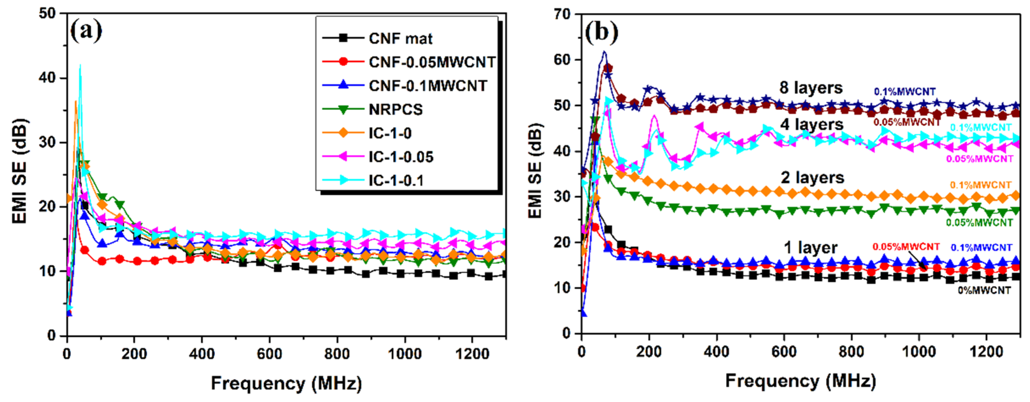
| ID Sample | Average EMI SE (dB) | SSE (dB·cm3·g−1) | SSE/t (dB·cm2·g−1) |
|---|---|---|---|
| CNF mat | 11.9 | 36.1 | 3281.8 |
| CNF-0.05MWCNT | 12.2 | 40.7 | 4522.2 |
| CNF-0.1MWCNT | 13.7 | 48.9 | 5433.3 |
| NRPCS | 13.9 | 14.1 | 1084.6 |
| IC-1-0 | 14.3 | 18.1 | 1810.0 |
| IC-1-0.05 | 15.4 | 19.5 | 1950.0 |
| IC-1-0.1 | 16.9 | 21.7 | 2170.0 |
| IC-2-0.1 | 31.1 | 42.6 | 2662.5 |
| IC-4-0.1 | 41.5 | 59.3 | 1976.7 |
| IC-8-0.1 | 52.0 | 76.5 | 1176.9 |
| Material | Filler Content | t (mm) | EMI SE (dB) | SSE (dB·cm3·g−1) | SSE/t (dB·cm2·g−1) | Frequency Range (GHz) | Ref. |
|---|---|---|---|---|---|---|---|
| Flexible graphite (Grafoil) | N/A 1 | 3.1 | 130 | 118 | 606 | 1–2 | [51] |
| Carbon-carbon matrix composite + CCF | N/A | 2.4 | 124 | N/A | N/A | 0.0003−1.5 | [52] |
| EVA-SCF 2 sheets | 30 phr | 1.8−3.5 | 25 34 | N/A | N/A | 0.1–2 8–12 | [53] |
| LCP 3-CNF composites | 15 wt.% | 1.45 | ~41 | N/A | N/A | 0.015–1.5 | [54] |
| LCP-CNT composites | 50 wt.% | 1 | ~60 | N/A | N/A | 0.3–1.8 | [50] |
| WPU -CF-CNT film | 33 wt.% 13 wt. % | 0.15 | 34 | N/A | N/A | 0.05–1.5 | [49] |
| Graphene-CNT-Fe2O3 + PEDOT:PSS 4 film | N/A | 0.6 | 133 | N/A | N/A | 8–12 | [34] |
| PCL 5-MWCNT foam | 2 wt.% | 20 | 60–80 | 193–258 | 97–129 | 0.04–40 | [55] |
| MGNC 6 foam | PVDF 7 | 0.35 0.35 | 43 54 | 46 68 | 1324 1944 | 0–3 8.2–12.4 | [43] |
| PDMS 8-graphene foam | 0.8 wt.% | 1 | 30 | 500 | 5000 | 8–12 | [40] |
| PP-SSF 9 foam | 1.1 vol.% | 3.1 | 48 | 75 | 242 | 8–12.4 | [42] |
| WPU-MWCNT foam | 2.2 vol.% | 4.5 | 52 | 1148 | 2551 | 8.2–12.4 | [41] |
| PE-MWCNT BP laminates | N/A | 1.5 | ~100 | N/A | N/A | 2–18 | [23] |
| PVA-MLG 10 sandwich structure | 60 vol.% | 0.04-0.06 | 14 | N/A | N/A | 8.2–12.4 | [32] |
| PET-CF layered composite | N/A | 1.98 | 60 | N/A | N/A | 0.03–1.5 | [25] |
| CNF-MWCNT mat IC-8-0.1 interlayered composite | 0.1 wt.% 12 wt.% | 0.09 0.65 | 13.7 52 | 48.9 76.5 | 5433.3 1176.9 | 0.0003–1.3 | This work |
© 2019 by the authors. Licensee MDPI, Basel, Switzerland. This article is an open access article distributed under the terms and conditions of the Creative Commons Attribution (CC BY) license (http://creativecommons.org/licenses/by/4.0/).
Share and Cite
Ramírez-Herrera, C.A.; Gonzalez, H.; de la Torre, F.; Benitez, L.; Cabañas-Moreno, J.G.; Lozano, K. Electrical Properties and Electromagnetic Interference Shielding Effectiveness of Interlayered Systems Composed by Carbon Nanotube Filled Carbon Nanofiber Mats and Polymer Composites. Nanomaterials 2019, 9, 238. https://doi.org/10.3390/nano9020238
Ramírez-Herrera CA, Gonzalez H, de la Torre F, Benitez L, Cabañas-Moreno JG, Lozano K. Electrical Properties and Electromagnetic Interference Shielding Effectiveness of Interlayered Systems Composed by Carbon Nanotube Filled Carbon Nanofiber Mats and Polymer Composites. Nanomaterials. 2019; 9(2):238. https://doi.org/10.3390/nano9020238
Chicago/Turabian StyleRamírez-Herrera, Claudia Angélica, Homero Gonzalez, Felipe de la Torre, Laura Benitez, José Gerardo Cabañas-Moreno, and Karen Lozano. 2019. "Electrical Properties and Electromagnetic Interference Shielding Effectiveness of Interlayered Systems Composed by Carbon Nanotube Filled Carbon Nanofiber Mats and Polymer Composites" Nanomaterials 9, no. 2: 238. https://doi.org/10.3390/nano9020238
APA StyleRamírez-Herrera, C. A., Gonzalez, H., de la Torre, F., Benitez, L., Cabañas-Moreno, J. G., & Lozano, K. (2019). Electrical Properties and Electromagnetic Interference Shielding Effectiveness of Interlayered Systems Composed by Carbon Nanotube Filled Carbon Nanofiber Mats and Polymer Composites. Nanomaterials, 9(2), 238. https://doi.org/10.3390/nano9020238