Article

Bilayer MoSe2/HfS2 Nanocomposite as a Potential Visible-Light-Driven Z-Scheme Photocatalyst

1
School of Physical Science and Technology, Southwest University, Chongqing 400715, China
2
School of Electronic Information Engineering, Key Laboratory of Extraordinary Bond Engineering and Advanced Materials Technology of Chongqing, Yangtze Normal University, Chongqing 408100, China
3
Key Laboratory of Luminescent and Real-Time Analytical Chemistry, Ministry of Education, College of Chemistry and Chemical Engineering, Southwest University, Chongqing 400715, China
*
Authors to whom correspondence should be addressed.
Nanomaterials 2019, 9(12), 1706; https://doi.org/10.3390/nano9121706
Submission received: 29 October 2019 / Revised: 10 November 2019 / Accepted: 25 November 2019 / Published: 28 November 2019
(This article belongs to the Section Nanocomposite Materials)

Abstract

:
Visible-light-driven photocatalytic overall water splitting is deemed to be an ideal way to generate clean and renewable energy. The direct Z-scheme photocatalytic systems, which can realize the effective separation of photoinduced carriers and possess outstanding redox ability, have attracted a huge amount of interest. In this work, we have studied the photocatalytic performance of the bilayer MoSe2/HfS2 van der Waals (vdW) heterojunction following the direct Z-scheme mechanism by employing the hybrid density functional theory. Our calculated results show that the HfS2 and MoSe2 single layers in this heterojunction are used for the oxygen evolution reaction (OER) and hydrogen evolution reaction (HER), respectively. The charge transfer between the two layers brought about an internal electric field pointing from the MoSe2 layer to the HfS2 slab, which can accelerate the separation of the photoinduced electron–hole pairs and support the Z-scheme electron migration near the interface. Excitingly, the optical absorption intensity of the MoSe2/HfS2 heterojunction is enhanced in the visible and infrared region. As a result, these results reveal that the MoSe2/HfS2 heterojunction is a promising direct Z-scheme photocatalyst for photocatalytic overall water splitting.

1. Introduction

In order to set up a sustainable society, photocatalytic water splitting for hydrogen production has been deemed as an effective route to solve the problems of environmental pollution and energy shortage [1]. Owing to the groundbreaking work by Honda and Fujishima in 1972 [2], a variety of semiconductor materials have been extensively investigated to explore high-performance photocatalysts for water decomposition [3,4,5,6,7]. However, a majority of one-component photocatalysts, such as TiO2 and ZnO, can only utilize a small amount of the solar energy and the lifetimes of photoinduced electron–hole pairs in these materials are short, which leads to the problem that the photocatalytic efficiency is low and hampers their future applications [8,9]. For the sake of overcoming these disadvantages, many researchers have found that the construction of heterostructures, which are composed of different materials and can supply much greater control of the electronic and optical properties, is able to effectively enhance the catalytic activity [10,11,12,13,14,15].
In particular, great expectations have been placed on the Z-scheme photocatalytic mechanism—which includes two-step excitation and is illuminated by natural photosynthesis in plants [16]—for improving the utilization efficiency of sunlight [17,18,19,20,21,22,23,24]. Generally speaking, the Z-scheme photocatalytic system is made up of three parts: Catalysts for the hydrogen evolution reaction (HER), oxygen evolution reaction (OER), and the redox mediator for carrier migration [25]. According to this mechanism, although the isolated components cannot accomplish overall water splitting, the combined systems can decompose water into hydrogen and oxygen, which can broaden the scope of the promising photocatalysts. Moreover, the Z-scheme photocatalytic composites possess strong redox abilities and can benefit the separation of photogenerated carriers because of the occurrence of HER and OER on different layers [26]. Nevertheless, the redox mediators in Z-scheme photocatalysts may induce undesired back reactions and seriously affect the photocatalytic performance [27]. Z-scheme systems without mediators, which are named as direct Z-scheme photocatalysts, can avoid the problems caused by mediators and are easier to experimentally fabricate owing to their simpler structures. Therefore, the direct Z-scheme systems have been extensively studied [28,29,30,31,32].
Recently, various two-dimensional (2D) materials, such as graphene [33], g-C3N4 [34], MoSe2 [35], and HfS2 [36] have been predicated and fabricated [37]. Owing to the maximized specific surface area, high charge migration, and unique electronic properties derived from the quantum confinement effect, 2D materials and related heterostructures have attracted much attention as high-performance photocatalysts for water [38,39,40]. However, being limited by the band edge positions, the isolated MoSe2 and HfS2 monolayers can only be used for the HER and OER [41,42], respectively. Fortunately, the band edge positions of MoSe2 and HfS2 single layers present staggered-type (type II) band alignment characteristics [43,44], which are beneficial for establishing the Z-scheme composites. Therefore, we have designed MoSe2/HfS2 bilayer nanocomposites and studied their geometric structures, band structures, density of states, charge transfer, stress effect, and optical properties by employing the hybrid density functional theory.

2. Computational Method

In this work, all of the density functional theory calculations were employed with the Vienna ab initio simulation package (VASP) [45]. The frozen-core projector augmented wave (PAW) was used to describe the interaction between the core and valence electrons [46,47]. The generalized gradient approximation (GGA) [48] of the Perdew–Burke–Ernzerhof (PBE) exchange correlation functional [49] was adopted. The charge redistribution in the MoSe2/HfS2 heterojunction was considered by calculating the dipole correction [50]. For the sake of avoiding the undervaluation of bandgaps calculated by the PBE method, the electronic and optical properties of these referred materials were calculated by the Heyd–Scuseria–Ernzerhof (HSE) hybrid functional by adding a part of the exact exchange interaction [51]. An exact exchange contribution of 0.25 was used in this study. The long-range van der Waals (vdW) interaction of heterojunctions was described by the Grimmes DFT-D3 method [52]. A Γ-centered 7 × 7 × 1 K-point was used to sample the 2D Brillouin Zone [53]. The cutoff energy was set as 500 eV. The convergence criteria were less than 10−5 eV for total energy and 0.01 eV/Å for Hellman–Feynman force on each atom, respectively. A vacuum space of 20 Å was inserted perpendicular to the layers to separate the neighboring slabs of heterojunctions. The band edge positions of 2D materials were calculated by subtracting vacuum levels, which were obtained by averaging the values in the LOCPOT file; they were then applied for measuring the absolute positions of energy bands.

3. Results and Discussion

3.1. Structural Stability

In this study, we chose the hexagonal MoSe2 and HfS2 monolayers, which are able to fit each other well. After the structural optimization, the lattice constants of MoSe2 and HfS2 single layers were 3.30 Å and 3.61 Å, respectively, which agree with the previous values [54]. Due to the small lattice mismatch of these single layers, we designed a heterojunction composed of 2 × 2 MoSe2 and HfS2 supercells. In order to probe into the steadiest stacked pattern, we studied various configurations. The steadiest configuration of the MoSe2/HfS2 heterojunction, whose equilibrium structure is presented in Figure 1, will be studied in the subsequent parts.
In addition, the interlayer spacing of the MoSe2/HfS2 heterobilayer was 3.05 Å, as displayed in Figure 1, which refers to the vertical distance from the nearest S atoms of the HfS2 layer to the Se atoms of the MoSe2 layer. This vertical separation between two layers is a typical vdW equilibrium distance, which is in accord with other 2D vdW heterostructures [11,44]. Thus, it was necessary to add the vdW corrections into our computation. The binding energy (Eb) of the MoSe2/HfS2 heterojunction can be defined as this equation: Eb = EMoSe2/HfS2 − E MoSe2 − E HfS2, where EMoSe2/HfS2, E MoSe2, and E HfS2 stand for the total energy of this heterostructure, isolated MoSe2, and HfS2 monolayers, respectively. After calculations, the bound energy of the steadiest configuration of the MoSe2/HfS2 heterojunction is –0.27 eV, which means that this composite is stable.

3.2. Electronic Properties

The band structures of related materials were calculated by employing the hybrid functional. As presented in Table 1, the bandgaps of MoSe2 and HfS2 monolayers were 2.02 and 1.99 eV, respectively, which are consistent with the previous calculations [54] and mean that the two layers can both utilize the visible light irradiation. Moreover, the valence band maximum (VBM) and conduction band minimum (CBM) of the HfS2 monolayer were both lower than those of MoSe2 single layer, which indicates that MoSe2/HfS2 heterobilayer can form a type II heterostructure. As we all know, all of the direct Z-scheme systems have a typical type II band alignment structure [26]. Therefore, the MoSe2/HfS2 heterojunction can form a direct Z-scheme photocatalyst.
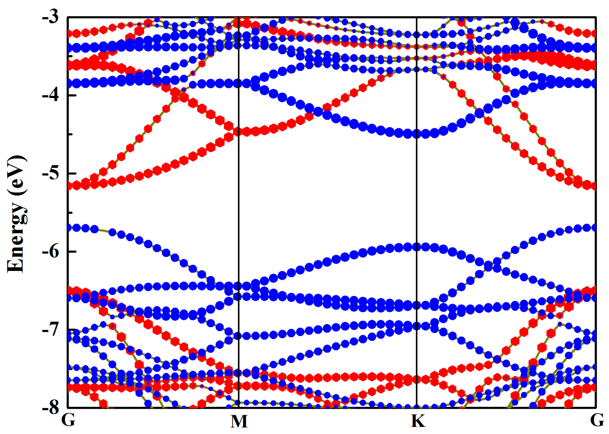
Meanwhile, the VBM of the HfS2 single layer was able to stride over the standard oxidation potential for O2/H2O, whereas the CBM was 0.5 eV lower than the standard reduction potential for H+/H2. So, the HfS2 monolayer can only be used for OER. At the same time, the VBM of the MoSe2 monolayer was 0.04 eV higher than the standard oxidation potential, while the CBM could straddle the standard reduction potential, indicating that the MoSe2 single layer can only be applied for HER. Thus, by combining the MoSe2 and HfS2 single layers, the MoSe2/HfS2 nanocomposite can be used for photocatalytic overall water splitting. As depicted in Figure 2, the MoSe2/HfS2 heterostructure is a semiconductor with a direct bandgap of 0.53 eV, which is less than those of the individual MoSe2 (2.02 eV) and HfS2 (1.99 eV) single layers, indicating that this heterojunction can make the best of visible light and even enlarge the applied range of light to infrared light. As shown in the picture of the projected band structure, the VBM of this heterostructure is mainly composed of the MoSe2 layer, while the CBM is primarily made up of the HfS2 layer, which is in support of the separation of the photoinduced carriers.
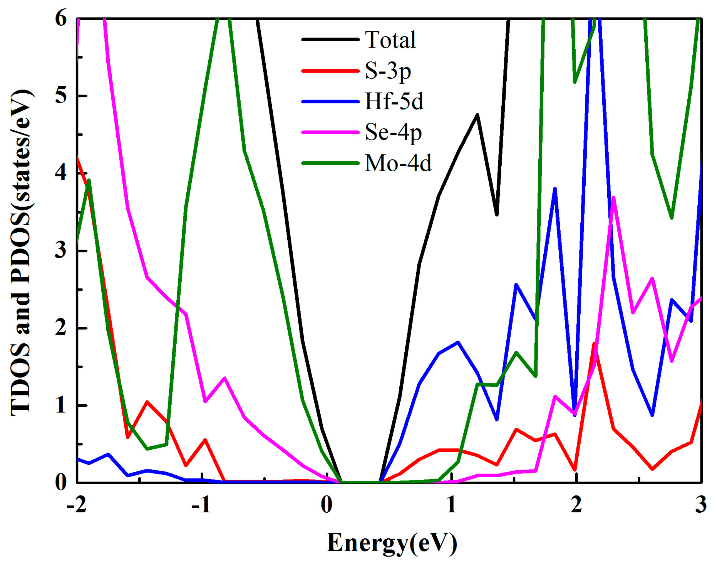
In order to systematically study the photocatalytic ability of the MoSe2/HfS2 heterostructure, we employed a density of states (DOS) analysis. TDOS and PDOS represent the total and partial DOS, respectively. As displayed in Figure 3, the VBM of this heterojunction chiefly consisted of the Mo 4d and Se 4p states, which were derived from the MoSe2 layer. However, the CBM was primarily made up of the Hf 5d and S 3p orbitals, which were rooted in the HfS2 slab. Thus, the VBM and CBM of this heterojunction were separated into different layers, which is consistent with the previous analysis about the band structure.
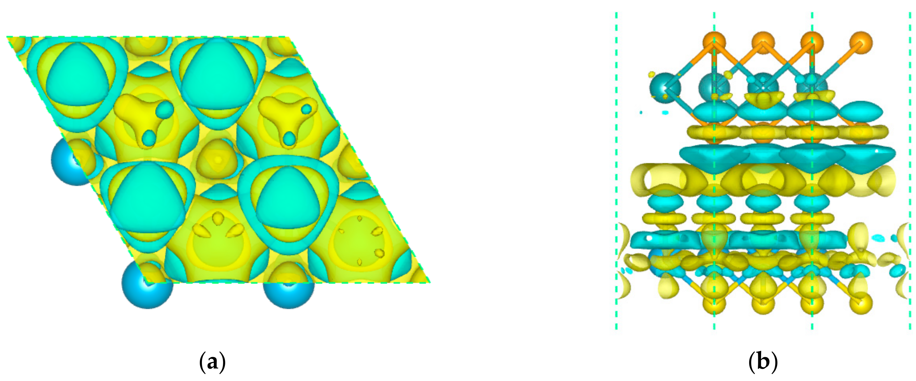
The effective separation of the photo-generated electron–hole pairs is an essential factor for improving the photocatalytic activity. Thus, we applied the charge density difference and Bader charge analysis to investigate the carrier migrating processes. The charge density differences of this heterostructure are defined as this: △ρ = ρMoSe2/HfS2 − ρMoSe2 − ρHfS2, where ρMoSe2/HfS2, ρMoSe2, and ρHfS2 indicate the charge density of the MoSe2/HfS2 nanocomposite, freestanding MoSe2, and HfS2 nanosheets, respectively. The small bandgap (0.53 eV) in this heterostructure was favorable to enhancing the interlayer carrier transfer. As depicted in Figure 4, there is obvious charge accumulation and depletion near the interface. The MoSe2 layer was apt to lose charge, while the HfS2 slab tended to gain charge. Hence, the charge transfer between two layers brought about an internal electric field pointing from the MoSe2 layer to the HfS2 slab, which is in accordance with the previous report that the electric field generally points from the hydrogen evolution catalyst to the oxygen evolution catalyst [25]. In order to evaluate the quantity of charge transfer, we employed the Bader charge analysis. The S and Se atoms were liable to acquire electrons, while the Hf and Mo atoms were apt to lose electrons. As a whole, the migrated electrons from the MoSe2 layer to the HfS2 slab were 0.052 e, which is in keeping with the charge density differences analysis.
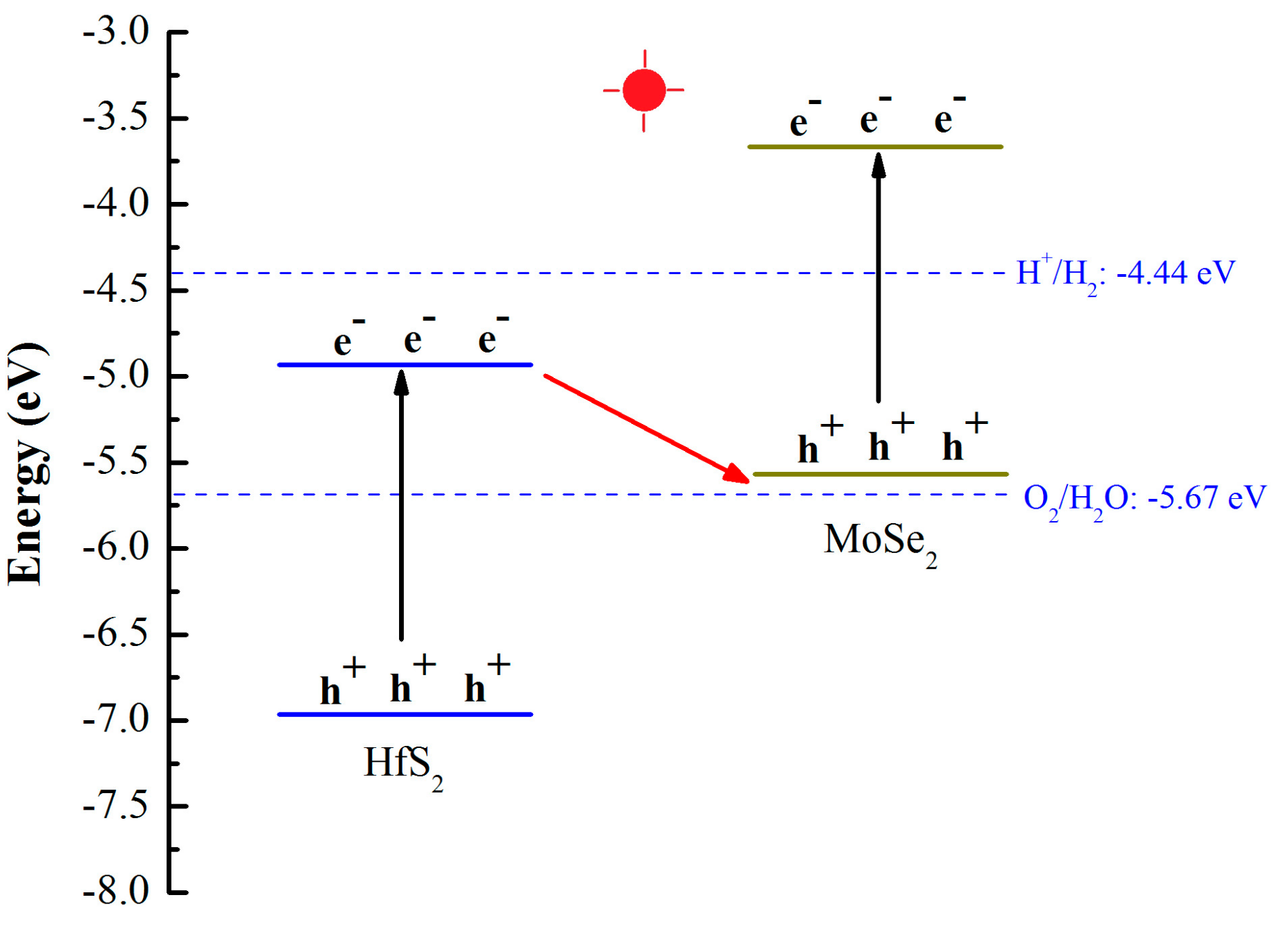
After the light irradiation, the electrons on the VB of MoSe2 and HfS2 slabs were excited to the CB of these layers. The internal electric field of the MoSe2/HfS2 nanocomposite was in favor of the electron migration from the CB of HfS2 to the VB of MoSe2. Meanwhile, the electric field hindered the electron transfer from the CB of MoSe2 to the CB of HfS2 and the hole transfer from the VB of HfS2 to the VB of MoSe2. Moreover, because the CBM of HfS2 and VBM of MoSe2 were close to each other (0.69 eV)—as displayed in Table 1—the photogenerated electrons in the CBM of HfS2 layer could easily recombine with the holes in the VBM of the MoSe2 layer. Finally, the photoinduced electrons in the CBM of MoSe2 slab and the holes in the VBM of HfS2 slab could both be preserved, which enabled the MoSe2/HfS2 nanocomposite to possess high redox ability. The schematic illustration of the Z-scheme photocatalytic mechanism for the MoSe2/HfS2 nanocomposite is illustrated in Figure 5. Therefore, in comparison with the MoSe2 and HfS2 monolayers, the MoSe2/HfS2 heterostructure can improve the separation efficiency of the photogenerated carriers and enhance the redox ability.
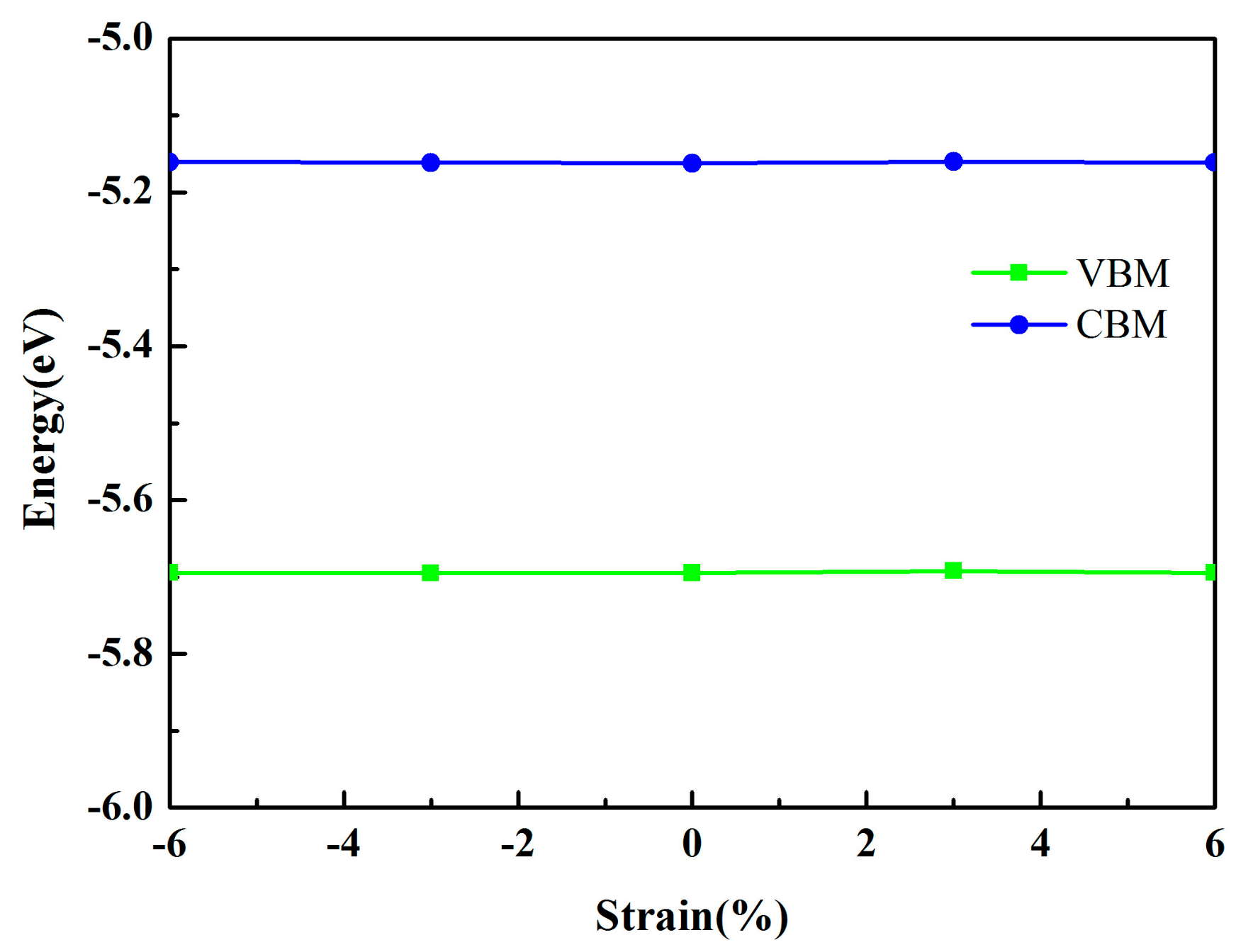
In addition, stress is inevitable in industrial production and may also originate from the mismatch of the lattices between different materials. Thus, we investigated the band edge positions of the MoSe2/HfS2 nanocomposite as a function of in-plain strains. By applying the strains in the range from −6% to 6%, the calculated band edge positions of the MoSe2/HfS2 heterostructure remained almost unchanged, as displayed in Figure 6. Thus, the band structures of MoSe2/HfS2 heterostructure are stable, which is different from the typical type II heterojunctions [11,15]. Therefore, the stable electronic property is in favor of future industrial applications.

3.3. Optical Properties

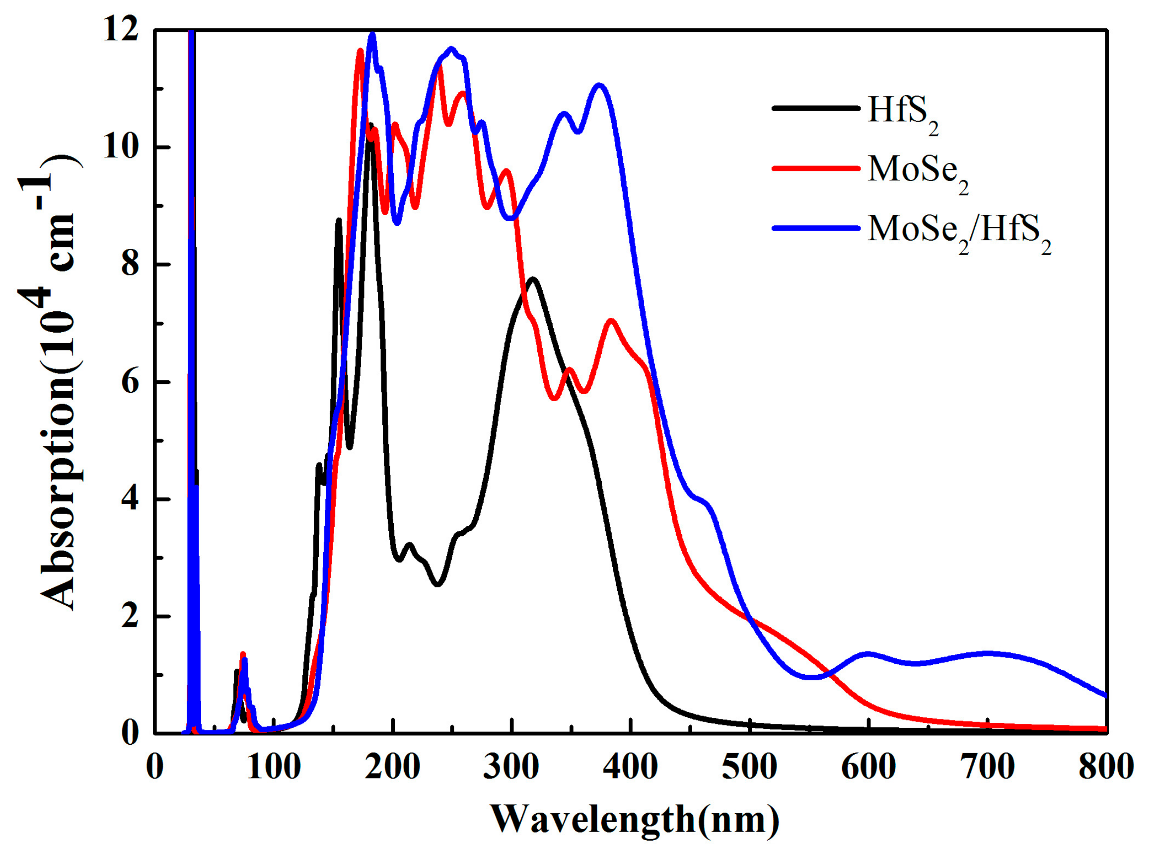
Optical absorption spectra are able to directly characterize the catalytic performance of photocatalysts. In this work, we employed the VASPKIT software to analyze the optical absorption properties. The optical absorption coefficient I(ω) can be acquired from the dynamical dielectric response function ε(ω), which can be expressed by this equation: I ( ω ) = 2 ω [ ε 1 ( ω ) 2 + ε 2 ( ω ) 2 ε 1 ( ω ) ] 1 2 . Compared with those of the HfS2 and MoSe2 monolayers, the optical absorption intensity of the MoSe2/HfS2 heterostructure is strengthened, especially in the visible and infrared region, as shown in Figure 7. Because the HfS2 single layer is an indirect semiconductor, the enhancement of the optical absorption mainly stems from the MoSe2 monolayer, which possesses a direct bandgap. Moreover, the evident red shift in this nanocomposite is mainly derived from the transition from the S 3p state to the Se 4p state. Furthermore, there are obvious absorption peaks even at 400 and 600 nm. Therefore, the MoSe2/HfS2 can take full advantage of the visible light.

4. Conclusions

To summarize, we have designed a MoSe2/HfS2 bilayer heterostructure and investigated its electronic and optical properties according to the direct Z-scheme mechanism by employing the hybrid density functional theory. The computed results reveal that the HfS2 monolayer and MoSe2 single layer can only be used for OER and HER, respectively. By combining the MoSe2 and HfS2 monolayers, the MoSe2/HfS2 nanocomposite, which is a direct Z-scheme photocatalyst, can be used for photocatalytic overall water splitting. As depicted in the projected band structure, the VBM of this heterostructure is mainly composed of the MoSe2 layer, while the CBM is primarily made up of the HfS2 layer. By applying the charge density difference and Bader charge analyses, the charge transfer between two layers brought about a built-in electric field pointing from the MoSe2 layer to the HfS2 slab, which is in support of the separation of the photoinduced carriers. Moreover, the photogenerated electrons in the CBM of the MoSe2 slab and the holes in the VBM of the HfS2 slab can both be preserved, which enables the MoSe2/HfS2 nanocomposite to possess high redox ability. When strains are applied to the MoSe2/HfS2 heterostructure, the band structures of this heterostructure are stable, which is in favor of future industrial applications. Compared with those of HfS2 and MoSe2 monolayers, the optical absorption intensity of the MoSe2/HfS2 heterostructure is distinctly strengthened in the visible and infrared region. Therefore, the MoSe2/HfS2 heterojunction is a potential direct Z-scheme photocatalyst for photocatalytic overall water splitting. This work may provide an effective route for developments in clean and renewable energy.

Author Contributions

The study was proposed and planned by H.C. The calculations were carried out by B.W., X.W., P.W., T.Y., H.Y., and G.W. discussed the results, B.W. wrote the manuscript.

Funding

This work has been financially supported by the National Natural Science Foundation of China (Grant Nos.11875226 and 11874306), the Natural Science Foundation of Chongqing (Grant No. CSTC-2017jcyjBX0035), the Fundamental Research Funds for the Central Universities (Grant Nos. XDJK2017C062 and XDJK2017B020), and the educational reform Research Funds of Southwest Universities (Grant No. 2018JY0730).

Acknowledgments

Biao Wang thanks Anlong Kuang and Junli Chang (from Southwest University) for their help in this work.

Conflicts of Interest

The authors declare no conflict of interest.

References

  1. Miseki, Y.; Sayama, K. Photocatalytic Water Splitting for Solar Hydrogen Production Using the Carbonate Effect and the Z-Scheme Reaction. Adv. Energy Mater. 2018, 1801294. [Google Scholar] [CrossRef]
  2. Fujishima, A.; Honda, K. Electrochemical photolysis of water at a semiconductor electrode. Nature 1972, 238, 37–38. [Google Scholar] [CrossRef] [PubMed]
  3. Eshete, Y.A.; Ling, N.; Kim, S.; Kim, D.; Hwang, G.; Cho, S.; Yang, H. Vertical Heterophase for Electrical, Electrochemical, and Mechanical Manipulations of Layered MoTe2. Adv. Funct. Mater. 2019, 1904504. [Google Scholar] [CrossRef]
  4. Bonaccorso, F.; Colombo, L.; Yu, G.; Stoller, M.; Tozzini, V.; Ferrari, A.; Ruoff, R.; Pellegrini, V. Graphene, related two-dimensional crystals, and hybrid systems for energy conversion and storage. Science 2015, 347, 41–51. [Google Scholar] [CrossRef]
  5. Fan, X.; Yang, Y.; Xiao, P.; Lau, W. Site-specific catalytic activity in exfoliated MoS2 single-layer polytypes for hydrogen evolution: Basal plane and edges. J. Mater. Chem. A 2014, 2, 20545–20551. [Google Scholar] [CrossRef]
  6. Singh, A.; Mathew, K.; Zhuang, H.; Hennig, R. Computational screening of 2D materials for photocatalysis. J. Phys. Chem. Lett. 2015, 6, 1087–1098. [Google Scholar] [CrossRef]
  7. Zhu, W.; Qiu, X.; Iancu, V.; Chen, X.; Pan, H.; Wang, W.; Dimitrijevic, N.M.; Rajh, T.; Meyer, H.M.; Paranthaman, M.P.; et al. Band gap narrowing of titanium oxide semiconductors by noncompensated anion-cation codoping for enhanced visible-light photoactivity. Phys. Rev. Lett. 2009, 103, 226401. [Google Scholar] [CrossRef]
  8. Wang, H.L.; Zhang, L.S.; Chen, Z.G.; Hu, J.Q.; Li, S.J.; Wang, Z.H.; Liu, J.S.; Wang, X.C. Semiconductor heterojunction photocatalysts: Design, construction, and photocatalytic performances. Chem. Soc. Rev. 2014, 43, 5234–5244. [Google Scholar] [CrossRef]
  9. Formal, F.L.; Pendlebury, S.R.; Cornuz, M.; Tilley, S.D.; Gratzel, M.; Durrant, J.R. Back electron-hole recombination in hematite photoanodes for water splitting. J. Am. Chem. Soc. 2014, 136, 2564–2574. [Google Scholar] [CrossRef]
  10. Deng, D.H.; Novoselov, K.S.; Fu, Q.; Zheng, N.F.; Tian, Z.Q.; Bao, X.H. catalysis with two-dimensional materials and their heterostructures. Nat. Nanotechnol. 2016, 11, 218–230. [Google Scholar] [CrossRef]
  11. Zhang, X.; Meng, Z.; Rao, D.; Wang, Y.; Shi, Q.; Liu, Y.; Wu, H.; Deng, K.; Liu, H.; Lu, R. Efficient band structure tuning, charge separation, and visible-light response in ZrS2-based van der Waals heterostructures. Energ. Environ. Sci. 2016, 9, 841–849. [Google Scholar] [CrossRef]
  12. Zhang, C.H.; Zhao, S.L.; Jin, C.H.; Koh, A.L.; Zhou, Y.; Xu, W.G.; Li, Q.C.; Xiong, Q.H.; Peng, H.L.; Liu, Z.F. Direct growth of large-area graphene and boron nitride heterostructures by a co-segregation method. Nature Commun. 2015, 6, 6519. [Google Scholar] [CrossRef] [PubMed]
  13. Kang, J.; Tongay, S.; Zhou, J.; Li, J.B.; Wu, J.Q. Band offsets and heterostructures of two-dimensional semiconductors. Appl. Phys. Lett. 2013, 102, 012111. [Google Scholar] [CrossRef]
  14. Ling, F.; Kang, W.; Jing, H.; Zeng, W.; Chen, Y.; Liu, X.; Zhang, Y.; Qi, L.; Fang, L.; Zhou, M. Enhancing hydrogen evolution on the basal plane of transition metal dichacolgenide van der Waals heterostructures. NPJ Comput. Mater. 2019, 5, 20. [Google Scholar] [CrossRef]
  15. Wang, B.; Yuan, H.K.; Chang, J.L.; Chen, X.R.; Chen, H. Two dimensional InSe/C2N van der Waals heterojunction as enhanced visible-light responsible photocatalyst for water splitting. Appl. Surf. Sci. 2019, 485, 375–380. [Google Scholar] [CrossRef]
  16. Bard, A.J. Photoelectrochemistry and heterogeneous photo-catalysis at semiconductors. J. Photochem. 1979, 10, 59–75. [Google Scholar] [CrossRef]
  17. Pan, Z.M.; Zhang, G.G.; Wang, X.C. Polymeric Carbon Nitride/RGO/Fe2O3: All Solid State Z-Scheme System for Photocatalytic Overall Water Splitting. Angew. Chem. Int. Ed. 2019, 58, 7102–7106. [Google Scholar] [CrossRef]
  18. Fu, C.F.; Luo, Q.Q.; Liao, X.X.; Yang, J.L. Two-dimensional van der waals nanocomposites as z-scheme type photocatalysts for hydrogen production from overall water splitting. J. Mater. Chem. A 2016, 4, 18892–18898. [Google Scholar] [CrossRef]
  19. Maeda, K. Z-scheme water splitting using two different semiconductor photocatalysts. ACS Catal. 2013, 3, 1486–1503. [Google Scholar] [CrossRef]
  20. Zhou, P.; Yu, J.G.; Jaroniec, M. All-solid-state z-scheme photocatalytic systems. Adv. Mater. 2014, 26, 4920–4935. [Google Scholar] [CrossRef]
  21. Li, J.Q.; Yuan, H.; Zhu, Z.F. Artificial photosynthetic z-scheme photocatalyst for hydrogen evolution with high quantum efficiencys. J. Mol. Catal. A Chem. 2015, 410, 133–139. [Google Scholar] [CrossRef]
  22. Wang, L.; Zheng, X.S.; Chen, L.; Xiong, Y.J.; Xu, H.X. Van der waals heterostructures comprised of ultrathin polymer nanosheets for efficient z scheme overall water splitting. Angew. Chem. Int. Ed. 2018, 57, 3454–3458. [Google Scholar] [CrossRef] [PubMed]
  23. Guo, H.L.; Du, H.; Jiang, Y.F.; Jiang, N.; Shen, C.C.; Zhou, X.; Liu, Y.N.; Xu, A.W. Artificial photosynthetic z-scheme photocatalyst for hydrogen evolution with high quantum efficiencys. J. Phys. Chem. C 2017, 121, 107–114. [Google Scholar] [CrossRef]
  24. Fan, Y.C.; Yang, B.; Song, X.H.; Shao, X.F.; Zhao, M.W. Direct z–scheme photocatalytic overall water splitting on 2D CdS/InSe heterostructures. J. Phys. D Appl. Phys. 2018, 51, 395501. [Google Scholar] [CrossRef]
  25. Fu, C.F.; Zhang, R.Q.; Luo, Q.Q.; Li, X.X.; Yang, J.L. Construction of Direct Z-Scheme Photocatalysts for Overall Water Splitting Using Two-Dimensional van der Waals Heterojunctions of Metal Dichalcogenides. J. Comput. Chem. 2019, 40, 980–987. [Google Scholar] [CrossRef]
  26. Ju, L.; Dai, Y.; Wei, W.; Li, M.M.; Huang, B.B. DFT investigation on two-dimensional GeS/WS2 van der Waals heterostructure for direct Z-scheme photocatalytic overall water splitting. Appl. Surf. Sci. 2018, 434, 365–374. [Google Scholar] [CrossRef]
  27. Li, H.; Tu, W.; Zhou, Y.; Zou, Z. Z-scheme photocatalytic systems for promoting photocatalytic performance: Recent progress and future challenges. Adv. Sci. 2016, 31, 500389. [Google Scholar] [CrossRef]
  28. Di, T.M.; Zhu, B.C.; Cheng, B.; Yu, J.G.; Xu, J.S. A direct Z-scheme g-C3N4/SnS2 photocatalyst with superior visible-light CO2 reduction performance. J. Catal. 2017, 352, 532–541. [Google Scholar] [CrossRef]
  29. Meng, A.Y.; Zhu, B.C.; Zhong, B.; Zhang, L.Y.; Cheng, B. Direct Z-scheme TiO2/CdS hierarchical photocatalyst for enhanced photocatalytic H2-production activity. Appl. Surf. Sci. 2017, 422, 518–527. [Google Scholar] [CrossRef]
  30. Liu, F.L.; Shi, R.; Wang, Z.; Weng, Y.X.; Che, C.M.; Chen, Y. Direct z scheme hetero-phase junction of black/red phosphorus for photocatalytic water splitting. Angew. Chem. Int. Ed. 2019, 58, 11791–11795. [Google Scholar] [CrossRef]
  31. Zhang, W.J.; Hu, Y.; Yan, C.Z.; Hong, D.C.; Chen, R.P.; Xue, X.L.; Yang, S.Y.; Tian, Y.X.; Tie, Z.X.; Jin, Z. Surface plasmon resonance enhanced direct Z-scheme TiO2/ZnTe/Au nanocorncob heterojunctions for efficient photocatalytic overall water splitting. Nanoscale 2019, 11, 9053–9060. [Google Scholar] [CrossRef] [PubMed]
  32. Wang, Q.; Hisatomi, T.; Jia, Q.; Tokudome, H.; Zhong, M.; Wang, C.; Pan, Z.; Takata, K.; Nakabayashi, M.; Shibata, N.; et al. Scalable water splitting on particulate photocatalyst sheets with a solar-to-hydrogen energy conversion eciency exceeding 1%. Nat. Mater. 2016, 15, 611–615. [Google Scholar] [CrossRef] [PubMed]
  33. Novoselov, K.; Geim, A.; Morozov, S.; Jiang, D.; Zhang, Y.; Dubonos, S.; Grigorieva, I.; Firsov, A. Electric field effect in atomically thin carbon films. Science 2004, 306, 666–669. [Google Scholar] [CrossRef] [PubMed] [Green Version]
  34. Zhao, Z.W.; Sun, Y.J.; Dong, F. Graphitic carbon nitride based nanocomposites: A review. Nanoscale 2015, 7, 15–37. [Google Scholar] [CrossRef]
  35. Coleman, J.N.; Lotya, M.; O’Neill, A.; Bergin, S.D.; King, P.J.; Khan, U.; Young, K.; Gaucher, A.; De, S.; Smith, R.J. Two-dimensional nanosheets produced by liquid exfoliation of layered materials. Science 2011, 331, 568–571. [Google Scholar] [CrossRef] [Green Version]
  36. Singh, D.; Gupta, S.K.; Sonvane, Y.; Kumarc, A.; Ahujad, R. 2D-HfS2 as an efficient photocatalyst for water splitting. Catal. Sci. Technol. 2016, 6, 6605–6614. [Google Scholar] [CrossRef]
  37. Zhang, H. Ultrathin two-dimensional nanomaterials. ACS Nano 2015, 9, 9451–9469. [Google Scholar] [CrossRef]
  38. Novoselov, K.S.; Mishchenko, A.; Carvalho, A.; Neto, A.H.C. 2D materials and van der Waals heterostructures. Science 2016, 353, 461–473. [Google Scholar] [CrossRef] [Green Version]
  39. Zhuang, H.; Hennig, R. Theoretical perspective of photocatalytic properties of single-layer SnS2. Phys. Rev. B 2013, 88, 115314. [Google Scholar] [CrossRef]
  40. Zhuang, H.; Hennig, R. Single-layer group-III monochalcogenide photocatalysts for water splitting. Chem. Mater. 2013, 25, 3232–3238. [Google Scholar] [CrossRef]
  41. Yi, J.J.; Li, H.P.; Gong, Y.J.; She, X.J.; Song, Y.H.; Xu, Y.G.; Deng, J.J.; Yuan, S.Q.; Xu, H.; Li, H.M. Phase and interlayer effect of transition metal dichalcogenide cocatalyst toward photocatalytic hydrogen evolution: The case of MoSe2. Appl. Cata. B Environ. 2019, 243, 330–336. [Google Scholar] [CrossRef]
  42. Zhu, J.D.; Xu, S.R.; Ning, J.; Wang, D.; Zhang, J.C.; Hao, Y. Gate-Tunable Electronic Structure of Black Phosphorus/HfS2 P−N van der Waals Heterostructure with Uniformly Anisotropic Band Dispersion. J. Phys. Chem. C 2017, 121, 24845–24852. [Google Scholar] [CrossRef]
  43. Xu, Y.; Zhao, W.; Xu, R.; Shi, Y.; Zhang, B. Synthesis of ultrathin CdS nanosheets as efficient visible-light-driven water splitting photocatalysts for hydrogen evolution. Chem. Commun. 2013, 49, 9803–9805. [Google Scholar] [CrossRef] [PubMed]
  44. Wang, B.; Kuang, A.L.; Luo, X.K.; Wang, G.Z.; Yuan, H.K.; Chen, H. Bandgap engineering and charge separation in two-dimensional GaS-based van der Waals heterostructures for photocatalytic water splitting. Appl. Surf. Sci. 2018, 439, 374–379. [Google Scholar] [CrossRef]
  45. Kresse, G.; Furthmüller, J. Efficient iterative schemes for ab initio total energy calculations using a plane-wave basis set. Phys. Rev. B 1996, 54, 11169–11186. [Google Scholar] [CrossRef]
  46. Kresse, G.; Joubert, D. From ultrasoft pseudopotentials to the projector augmented-wave method. Phys. Rev. B 1999, 59, 1758–1775. [Google Scholar] [CrossRef]
  47. Blöchl, P.E. Projector augmented wave method. Phys. Rev. B 1994, 540, 17953–17979. [Google Scholar] [CrossRef] [Green Version]
  48. White, J.A.; Bird, D.M. Implementation of gradient-corrected exchange correlation potentials in Car-Parrinello total-energy calculations. Phys. Rev. B 1994, 50, 4954–4957. [Google Scholar] [CrossRef]
  49. Ernzerhof, M.; Scuseria, G.E. Assessment of the Perdew-Burke-Ernzerh of exchange-correlation functional. J. Chem. Phys. 1999, 110, 5029–5036. [Google Scholar] [CrossRef] [Green Version]
  50. Bengtsson, L. Dipole correction for surface supercell calculations. Phys. Rev. B 1999, 50, 12301. [Google Scholar] [CrossRef]
  51. Heyd, J.; Scuseria, G.E. Hybrid functionals based on a screened Coulomb potential. J. Chem. Phys. 2003, 118, 8207–8215. [Google Scholar] [CrossRef] [Green Version]
  52. Grimme, S.; Antony, J.; Ehrlich, S.; Krieg, S. A consistent and accurate ab initio parametrization of density functional dispersion correction (DFT-D) for the 94 elements H-Pu. J. Chem. Phys. 2010, 132, 154104. [Google Scholar] [CrossRef] [PubMed] [Green Version]
  53. Monkhorst, H.J.; Pack, J.D. Special points for Brillouin-zone integrations. Phys. Rev. B 1976, 13, 5188–5192. [Google Scholar] [CrossRef]
  54. Ramasubramaniam, A. Large excitonic effects in monolayers of molybdenum and tungsten dichalcogenides. Phys. Rev. B 2012, 86, 115409. [Google Scholar] [CrossRef] [Green Version]
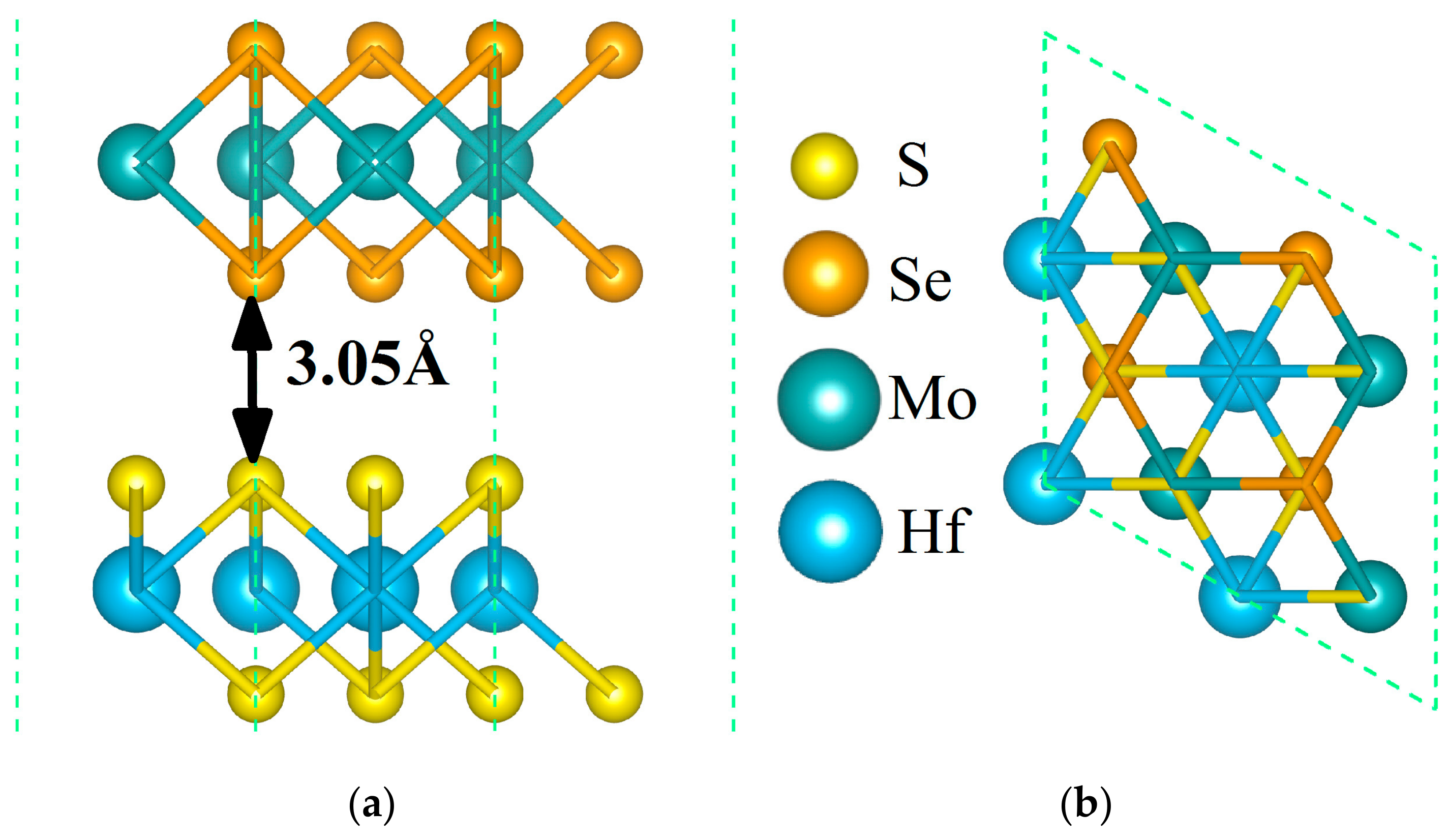
Figure 1. The equilibrium structure of the MoSe2/HfS2 nanocomposite. Orange and peacock-blue balls signify Se and Mo atoms in the MoSe2 monolayer; yellow and dodger-blue balls symbolize S and Hf atoms in the HfS2 single layer, respectively. The side view (a) and top view (b) of this heterojunction.
Nanomaterials 09 01706 g001
Figure 2. Projected band structure of the MoSe2/HfS2 heterostructure. The red hexagons and blue balls represent the energy bands of the HfS2 and MoSe2 layers, respectively.
Nanomaterials 09 01706 g002
Figure 3. Total and partial density of states of the MoSe2/HfS2 nanocomposite.
Nanomaterials 09 01706 g003
Figure 4. Electron density difference in the MoSe2/HfS2 nanocomposite with an isovalue of 0.0001 e/Å3. Yellow and cyan areas represent accumulation and depletion, respectively. Charge density differences for the MoSe2/HfS2 heterojunction (top view (a) and side view(b)).
Nanomaterials 09 01706 g004
Figure 5. The schematic illustration of the Z-scheme photocatalytic mechanism for the MoSe2/HfS2 nanocomposite.
Nanomaterials 09 01706 g005
Figure 6. The band edge positions of the MoSe2/HfS2 nanocomposite as a function of in-plain strains.
Nanomaterials 09 01706 g006
Figure 7. Optical absorption spectra of the related 2D materials and nanocomposite.
Nanomaterials 09 01706 g007
Table 1. Bandgaps and band edge positions of the related nanosheets.
StructureEg (eV)EVBM (eV)ECBM (eV)Bandgap Type
MoSe22.02−5.63−3.61Direct
HfS21.99−6.93−4.94Indirect
MoSe2/HfS20.53−5.69−5.16Direct
MoSe2/HfS2 with −6% strain0.53−5.69−5.16Direct
MoSe2/HfS2 with −3% strain0.54−5.70−5.16Direct
MoSe2/HfS2 with 3% strain0.53−5.69−5.16Direct
MoSe2/HfS2 with 6% strain0.53−5.69−5.16Direct