Article

Basic Medium Heterogeneous Solution Synthesis of α-MnO2 Nanoflakes as an Anode or Cathode in Half Cell Configuration (vs. Lithium) of Li-Ion Batteries

1
Materials Science and Engineering, Purdue University, West Lafayette, IN 47907, USA
2
Department of Biomaterials and Technology, Swedish University of Agricultural Sciences, Box 7008, SE-75007 Uppsala, Sweden
3
Department of Molecular Sciences, Swedish University of Agricultural Sciences, Box 7015, SE-75007 Uppsala, Sweden
4
Davidson School of Chemical Engineering, Purdue University, West Lafayette, IN 47907, USA
*
Authors to whom correspondence should be addressed.
Nanomaterials 2018, 8(8), 608; https://doi.org/10.3390/nano8080608
Submission received: 18 July 2018 / Revised: 4 August 2018 / Accepted: 7 August 2018 / Published: 9 August 2018

Abstract

:
Nano α-MnO2 is usually synthesized under hydrothermal conditions in acidic medium, which results in materials easily undergoing thermal reduction and offers single crystals often over 100 nm in size. In this study, α-MnO2 built up of inter-grown ultra-small nanoflakes with 10 nm thickness was produced in a rapid two-step procedure starting via partial reduction in solution in basic medium subsequently followed by co-proportionation in thermal treatment. This approach offers phase-pure α-MnO2 doped with potassium (cryptomelane type K0.25Mn8O16 structure) demonstrating considerable chemical and thermal stability. The reaction pathways leading to this new morphology and structure have been discussed. The MnO2 electrodes produced from obtained nanostructures were tested as electrodes of lithium ion batteries delivering initial discharge capacities of 968 mAh g−1 for anode (0 to 2.0 V) and 317 mAh g−1 for cathode (1.5 to 3.5 V) at 20 mA g−1 current density. At constant current of 100 mA g−1, stable cycling of anode achieving 660 mAh g−1 and 145 mAh g−1 for cathode after 200 cycles is recorded. Post diagnostic analysis of cycled electrodes confirmed the electrode materials stability and structural properties.

Graphical Abstract

1. Introduction

Lithium ion batteries (LIB) have attracted huge attention in the battery industry since their introduction in the early 1990s by Sony. The growing attention to large intermittent devices and electric vehicles requires high energy and high power density batteries. Thereby, developing LIB with good performance and excellent stability becomes essential. Metal oxides are studied as electrode materials for LIB due to their high theoretical capacity compared to graphite [1,2,3,4]. Among various transition metal oxides, manganese-based oxides (MnO, Mn2O3, Mn3O4, and MnO2) have attracted huge interest as electrode materials for their high theoretical capacity, eco-friendliness, cost-effectiveness, and natural abundance [5]. Based on the conversion reaction of each manganese oxide, the theoretical capacity is 750, 936, 1018, and 1230 mAh g−1 for MnO, Mn3O4, Mn2O3, and MnO2, respectively. Traditionally, MnO2 is applied as a material for primary lithium batteries and capacitors [6,7]. Recently, the interest in lithium-ion batteries has increased as well for their high theoretical capacity among four different types of manganese oxides [8,9].
However, MnO2 as an electrode material in secondary ion batteries has been hindered by the large volume expansion, poor conductivity, and poor reversibility [5,8]. To address such an issue, several strategies have been suggested including MnO2 composite material and fabricating nano-structured MnO2. Li et al. wrapped MnO2 with graphene to resolve the conductivity issue [10]. The initial capacity was 1200 mAh g−1 and a stable capacity of 600 mAh g−1 at 400 mA g−1 current density was maintained. MnO2 composite with improved conductivity has been realized by using graphene [11], carbon nanotube [12], and other metal oxides [13,14,15]. The size, crystallinity, and morphology control of MnO2 are important factors that influence the performance. Thereby, it is essential to choose the proper synthesis method. Numerous reports use the acidic medium fabrication method to prepare MnO2. Chen et al. have prepared MnO2 nano-rods using KMnO4 and HCl via the hydrothermal method [8]. The prepared nano-rods have shown an initial capacity of 1200 mAh g−1. However, the cycle performance was unstable. Another example of using acidic medium in hydrothermal process was reported by Feng and coworkers [16]. Despite the high initial capacity (1400 mAh g−1), the capacity drops to 600 mAh g−1 at second cycle. Li and coworkers prepared hollow urchin-like MnO2 via mixture of KMnO4 and sulfuric acid [17]. The hollow urchin morphology is obtained by the Ostwald ripening and delivered an initial capacity of 746 mAh g−1. Still, the cycle retention was 64% after 40 cycles. In addition to anode, there have also been few works on MnO2 as cathode material reported. Abuzeid et al. prepared MnO2 by using KMnO4 and extracts of green tea [5]. The prepared material showed an initial capacity of 236 mAh g−1 and 73% cycle retention after 20 cycles.
The majority of research used acidic medium for fabricating MnO2. Especially, hydrothermal approaches in acidic medium for preparation of the MnO2 are well reported [18,19]. In realization of this approach, a broad variety of precursors and conditions have been evaluated. In particular, acidic leaching of Mn(II) with H2SO4 from Mn2O3 has been reported [20,21]. Even decomposition of KMnO4 solutions in acidic medium at controlled low pH has been investigated [22]. The most thoroughly investigated tracks have been, however, the reduction of KMnO4 by HCl or by MnSO4 in acidic medium [23,24]. In addition, the use of organic polymers for permanganate reduction has been investigated [25,26]. Other approaches involved oxidation of MnSO4 solutions by potassium persulfate, K2S2O8, or by ozone [16]. Oxidation by atmospheric oxygen has also been used in the co-precipitation approach in basic medium that was using MnSO4 and MnC2O4 as Mn-sources. Despite acidic medium based MnO2 showed promising results, acidic medium results in partial reduction of Mn(IV) in the produced MnO2 nanostructures, leading potentially to lower capacity and instability in cycling of the produced electrode materials.
In this work, we report a successful fabrication of α-MnO2 nano flakes by reduction approaches in basic medium, securing preservation of the oxidation state +4. An unusual approach based on seeding of α-MnO2 through thermal treatment-induced interaction of amorphous MnO2, precipitated from permanganate by ammonia, with fine powder of stoichiometric amounts of Mn(II) carbonate resulted in interpenetrated network of phase-pure nanocrytalline material. Table 1 shows the comparison of current work to other’s work on MnO2 as electrode material. The structure analysis showed successful fabrication of nano-MnO2 particles. In addition, the preservation of MnO2 has been observed by Fourier Transformed Infrared Spectroscopy (FTIR) and Thermogravimetric Analysis (TGA). Basic medium based α-MnO2 showed successful results as electrode material for LIB and revealed a stable capacity of 690 mAh g−1 and 150 mAh g−1 at 100 mA g−1, respectively. The behavior of α-MnO2 was discussed by the voltage profile and cyclic voltammetry curves. To confirm that basic medium fabrication is compatible to conventional acidic medium based MnO2, the capacity values are compared.

2. Experimental

2.1. Synthesis of MnO2

All chemicals purchased from Sigma-Aldrich (Copenhahen, Denmark) were used without further purification. The synthesis was conducted under an ambient atmosphere. For preparation of α-MnO2 nano flakes, 0.2 g KMnO4 (1.28 mmol) was dissolved in 10 mL deionized water and a slurry of 0.5068 g of MnCO3·H2O (3.84 mmol) in 15 mL 25% NH3 solution was added. Constant stirring for 1 h at 80 °C were applied and then additional 5 mL 25% NH4OH were added and continued stirring for 1 h. The resulting brown precipitate was collected by decantation, washed and centrifuged with three portions of 10 mL of distilled water and dried in air overnight followed with heat treatment at 400 °C in air (heating up with the rate of 10 °C/min to 400 °C from room temperature and keeping then at this temperature for 4 h. The time was optimized experimentally by ex-situ X-ray Diffraction (XRD, Stockholm, Sweden) studies after different annealing times—2, 3, 4 and 6 h). The yield of resulting greyish black powder is 0.3781 g (86%).

2.2. Material Characterization

XRD studies of the powders were carried out with D8 SMART CCD Apex-II diffractometer (Bruker Nordic, Stockholm, Sweden) in rotation mode. SEM energy-dispersive X-ray spectroscopy (EDS) investigation was performed using Hitachi TM-1000-µ-DEX instrument (Spectral Solutions AB, Stockholm, Sweden). TEM investigation was made with Phillips CM12 instrument (Philips, Sweden). AFM studies have been performed with Bruker FastScan with ScanAsyst microscope (Blue Scientific, Stockholm, Sweden). FTIR studies were made with Spectrum 100 instrument (Perkin-Elmer, Upplands Väsby, Sweden). Thermogravimetric investigation was carried out with Pyris-1 thermobalance (Perkin-Elmer, Upplands Väsby, Sweden).

2.3. Electrochemistry

The electrochemical properties of α-MnO2 electrode materials were tested in half cells configuration with lithium-metal as counter-electrode as an anode (loading mass: 0.3 mg cm−2) and cathode (loading mass: 0.3 mg cm−2). 70% of prepared α-MnO2 was mixed with 20% conducting carbon (Timcal Super P, MTI Corporation, Richmond, CA, USA) and 10% PVDF (MTI Corporation, Richmond, CA, USA) binder in N-methyl-2-pyrrolidone (NMP) solvent. Obtained slurry was coated on aluminum (for cathode) and copper (for anode) current collectors. After drying overnight in a vacuum oven set at 80 °C, the prepared working electrode is assembled into 2032 coin cells (CR 2032) inside a glove box. Lithium foil (MTI Corporation, Richmond, CA, USA) was used as a counter-electrode, Cellgard 2500 (Charlotte, NC, USA) as a separator, and 1 M lithium hexafluorophosphate (LiPF6) salt in ethylene carbonate (EC)/diethyl carbonate (DEC) (Sigma Aldrich, St. Louis, MO, USA, 1:1 volume ratio) as an electrolyte. Galvanostatic charge-discharge profile was measured in the potential range of 0.01 V to 2 V for anode and 1.5 V to 3.5 V for cathode (BST8-MA, MTI, Richmond, CA, USA). In addition, cyclic voltammetry was performed by Gamry Reference 600+ equipment (Warminster, PA, USA) at a scanning rate of 0.1 mV s−1.

3. Results and Discussion

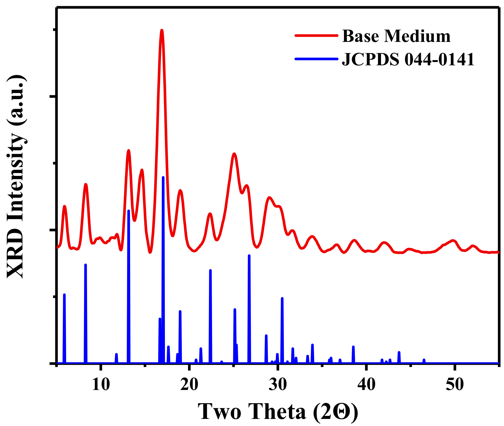
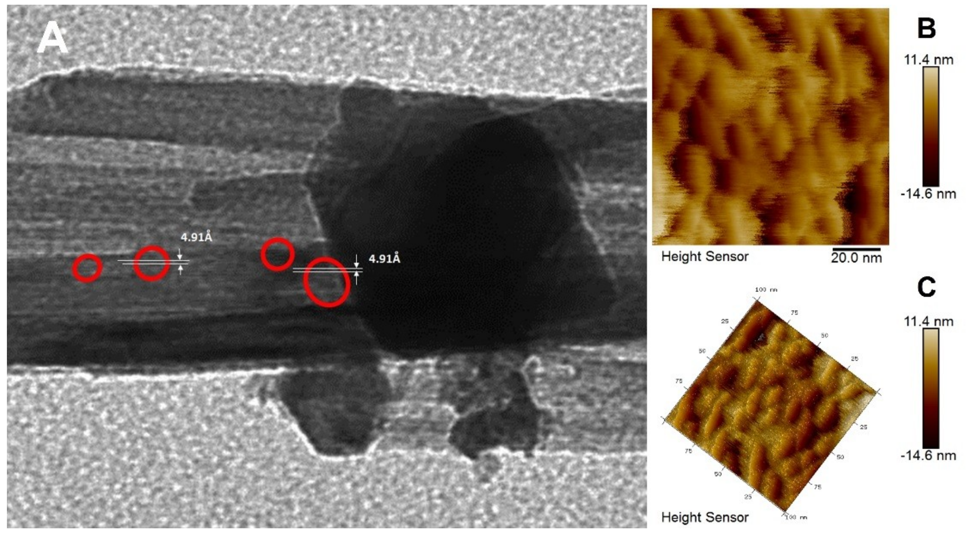
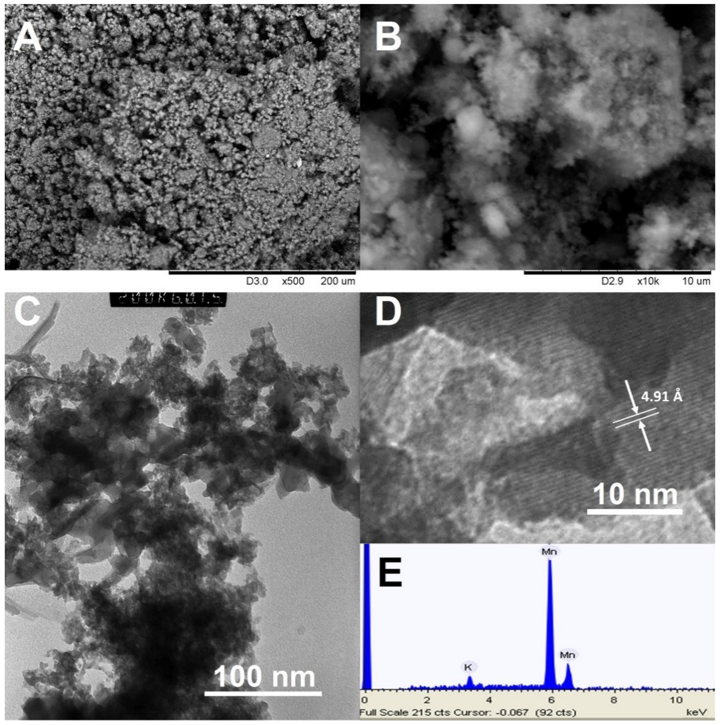
3.1. Synthesis and Structure of the Material

In preparation of manganese dioxide in basic medium, the reduction of potassium permanganate with concentrated ammonia was conducted. The proposed route involves setting together a solid phase, MnCO3(s), together with the solution of KMnO4 and NH3(aq). The reaction in the liquid phase provides amorphous KxMnO2+y (and N2(g) nitrogen), with oxidation state for Mn higher than +IV. In contact with MnCO3, this results apparently in seeding of MnO2(s) on the surface of the carbonate crystals. In subsequent thermal treatment, the whole mass is transformed into small-size α-MnO2 crystallites, both the amorphous part crystallizes with release of adsorbed water and breakdown of surface hydroxide groups and the solid MnCO3 is broken down with release of CO2. It is noteworthy that the thermal treatment of MnCO3 only gives as revealed by XRD in this work a complex mixture of Mn2O3, Mn3O4 and MnO2 (see Supplementary Figure S1) and also the heat-treatment of the amorphous mass, resulting from reduction of KMnO4 by NH3 on reflux in concentrated solution offers a complex mixture of phases after heat-treatment at over 600 °C (Figure S2). It is the combination of the two systems that results in practically phase-pure MnO2. Addition of a stoichiometric amount of manganese (II) carbonate, MnCO3, provides the necessary reducing agent not causing inclusion of other transition metal cations [27].
The product obtained from the initial reaction step in solution revealed a low-intensity X-ray diffraction pattern corresponding to MnCO3 together with an amorphous phase (see Supplementary Figure S3). Subsequent thermal treatment in 2 h at 400 °C led to a practically amorphous material according to XRD, while further treatment in 2 h resulted in a crystalline sample with XRD pattern corresponding to α-MnO2 phase (Figure 1). The average crystallite size calculated from Scherrer equation using the most intense line at 2θ = 16.987° (with Miller indices hkl = 211) is 108 nm. This is as stated only an average value as both smaller and bigger crystallites (over 100 nm) could be observed by TEM (see Figure 2). The peak at 2θ = 14.707° is corresponding to minor impurity of the residual MnCO3 (the most intense hkl = 104 line).
The SEM images (see Figure 2A,B) show strongly aggregated small particles forming low mass density solid material. The morphology of the prepared MnO2 revealed by TEM shows a flake-like structure with 0.491 nm 200 plane fringe pattern, which agrees to the Cryptomelane type α-MnO2 structure (Figure 2D). Low-charge cations are required to stabilize the Cryptomelane MnO2 structure—the formula of the natural Cryptomelane mineral is KMnIV7MnIIIO16 [28]. The α-MnO2 obtained in this work is apparently stabilized by the minor residual content of potassium in its composition. The Mn to K ratio was determined by EDS analysis and was found to be Mn:K = 32:1, i.e., only 25% of the additional positions in the Cryptomelane structure are thus occupied by the K-cations in the classic mineral structure, which here can be formulated as K0.25Mn8O16.
The flakes are connected in a very open interpenetrated network (Figure 2C) that is apparently formed through the thermal decomposition process associated with evolution of gases—both CO2 from MnCO3 crystals and water vapor from K-containing amorphous hydrated precipitate surrounding the carbonate crystals in the initial product of solution reaction. The process is straightforward and easy to carry out. The Brunauer-Emmett-Teller (BET) analysis was conducted to further confirm the interconnected structure (Figure S4). The pore distribution profile shows existence of various pore size in the prepared materials. This is attributed to the pore existing between interconnected MnO2 nanoparticles. In addition, the surface area (61.5 m2 g−1) is relatively higher than reported bulk MnO2 nanoparticles, which supports the interconnected structure as well [5,21].
Direct confirmation to the proposed mechanism could be obtained in the high resolution TEM and AFM studies of the intermediate reaction mixtures. As can be seen in Figure 3, the amorphous flakes containing K-cations and produced by decomposition of KMnO4 in the presence of ammonia commence to crystallize forming nuclei of the Cryptomelane type phase. The crystallites of MnCO3 are turned amorphous by the thermal treatment but keep their shape. The AFM images (Figure 3B,C) show clearly the rhombic shape blocks derived from the initial MnCO3 crystallites embedded into a less dense matrix. The final material is produced by crystallization accompanied with diffusion of potassium into these bigger blocks as the final material is single phase and has uniform potassium distribution in it according to EDS. The overall mechanism of the process can thus be described by Scheme 1.
The occurring chemical transformations can be described by the following reaction equations:
3KMnO4(aq) + (4 − 2x)NH3(aq) → 3KMnO2+x(s) + (2 − x)N2(g) + 6H2O
MnCO3(s) → MnO2−y + CO2(g)
KMnO2+x(s) + 3MnO2−y(s) → K0.25MnO2(s)

3.2. Stability Test of Produced α-MnO2

FTIR (Figure S5) shows the chemical information of samples kept at ambient condition. Minor degree of hydration (δ(O–H) at about 1600 and ν(O–H) at 3700 cm−1) and the network of metal-oxygen bonds present as characteristic bands (around 536 and 585 cm−1).
The TGA (Figure S6) shows the loss of hydrating water starting at room temperature and finishing at about 200 °C with the loss of 2.4–2.7% of the total weight in both air and nitrogen atmosphere. This process is followed by thermal decomposition with reduction of MnO2 into Mn3O4 in air at 500–620 °C (corresponding weight loss 6.1%) and into first Mn3O4 at 470–560 °C (weight loss of about 6%) and then Mn2O3 at 660–800 °C (further weight loss of about 3%) in N2 atmosphere. This confirms that MnO2 was produced when the heating was carried out to 400 °C with subsequent annealing and shows considerable thermal stability of the obtained material.

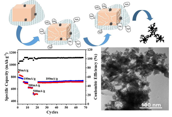
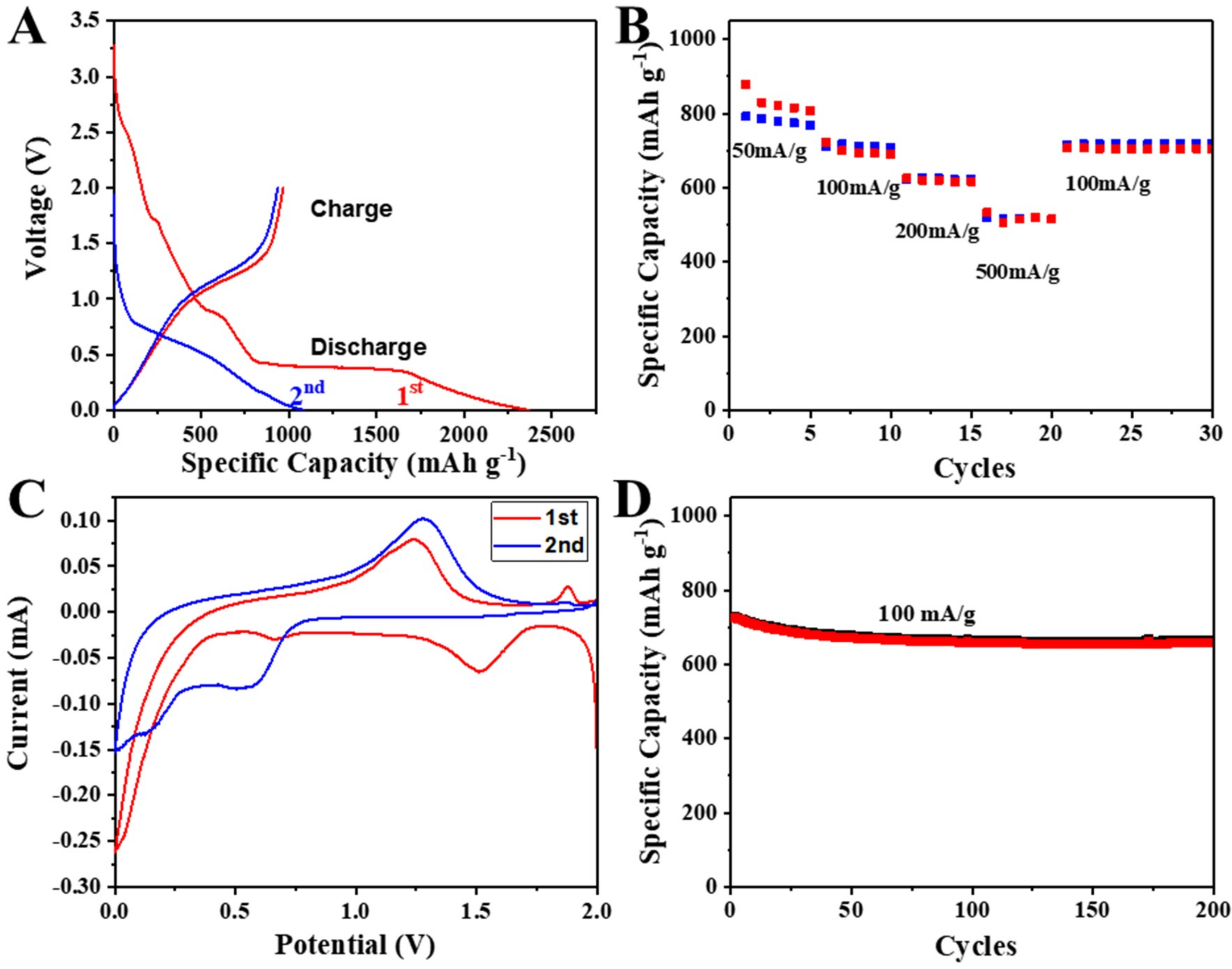
3.3. Electrochemical Performance

The α-MnO2 electrode was assembled and tested as anode and cathode separately vs. lithium (half cells) for lithium ion batteries. Figure 4A shows the voltage profiles of MnO2 for the initial two cycles at a current density of 20 mA g−1. It exhibits an initial discharge and charge capacity as 2369 and 968 mAh g−1, respectively, with a 59.1% first cycle Coulombic efficiency. The loss of capacity at the first cycle is attributed to the irreversible conversion reactions of lithium and MnO2 and the formation of solid electrolyte interphase (SEI) layer, which is obvious by the first cycle voltage profile slope and plateau in 1.5 to 0.7 V range [8]. The cyclic voltammetry (CV) was conducted to understand the kinetics (Figure 4C). The initial two cycles are scanned at a range of 0.01 to 2.0 V at a 0.1 mV s−1 scan rate. The CV curve for the first cycle shows a cathodic peak near 1.5 V which is not observed at the second cycle. The SEI layer and the irreversible conversion reaction between lithium and MnO2 shows the observed cathodic peak [16]. In addition, a broad peak appearance from 1.5–0.5 V corresponds to the reduction of MnO2 to Mn2+, and the peak near 0.1 V corresponds to the reduction of Mn2+ to metallic Mn0, which is easily found in other transition metal compounds for lithium ion batteries. An anodic peak appearance at 1.30 and 2.0 V is a response to the oxidation of Mn0 and Mn2+, respectively [8]. A shift in the second cycle explains a possible structure change induced by the formation of metallic manganese.
Figure 4B explains the rate performance of MnO2 as an anode at different current density. The rate study was conducted at various current densities, from 50 mA g−1 to 500 mA g−1. Stable capacities of 791 mAh g−1 and 517 mAh g−1 at current densities 50 mA g−1 and 500 mA g−1, respectively is obtained. The comparison of initial and final capacities at current densities 100 mA g−1 (711 mAh g−1 vs. 716 mAh g−1) shows excellent rate recovery after high rate performance. The cycle retention is 91% over 200 cycles (Figure 4D, 0.045% per cycle) which is relatively stable compared to other reports on MnO2 as anode (Table 1).
Numerous reports also focused on the possibility of using acid medium fabricated α-MnO2 as cathodic materials. To further ascertain that basic medium fabrication produced α-MnO2 is successful, its cathodic activities are tested at higher potential and compared (Table 1). The charge-discharge profile at a current density of 20 mA g−1 displayed an initial discharge and charge capacity as 477 and 317 mAh g−1, respectively, with a 33.4% capacity drop (Figure 5A). A plateau region occurring at a broad range over 2.5 to 2.2 V is attributed to the reduction of Mn4+ ions. The cyclic voltammetry (CV) shows analogous result to voltage profile, exhibiting an anodic peak at a similar range (oxidation of Mn2+ to Mn4+) with voltage profile (Figure 5C). The discharge capacity of 171 mAh g−1 recovered to 155 mAh g−1 after rate study (91% recover for cathode). The low capacity number at high current density can be explained by the sluggish kinetics of Li ion. Numerous reports compared the influence of Li ion conductivity on rate performance, showing low conductivity results in low rate performance [29,30]. The cycle retention of cathode is measured and displayed in Figure 5D. The capacity retention is 93% over 200 cycles (0.035% decrease per cycle).
Post-diagnostic analysis was carried out to determine whether the basic medium synthesized α-MnO2 is stable after long-term cycling (200 cycles). SEM and Raman analysis were performed on before and after cycled electrodes (both anode and cathode). The as-prepared electrode is composed of α-MnO2 (active material, conductive carbon (Super P), and PVDF binder (Figure 6A). It is observed that a uniform, homogeneous electrode is fabricated using α-MnO2 powder. The SEM image of cycled anode (Figure 6B) and cathode electrode (Figure 6C) shows that there is no obvious physical change in laminate. Raman spectroscopy of pristine electrode shows a peak positioned at 650, 1330, and 1598 cm−1, indicating presence of α-MnO2 (650 cm−1) and super P (conductive carbon), respectively [31,32,33]. For both cycled electrodes, the new Raman band appeared and the peak shows a broad feature compared to pristine electrode Raman peak (Figure 6D). The broad peak can be explained by the partial disordered phase of MnO2 after lithiation and delithiation process. After cycling, new Raman band appears at 484 and 430 cm−1, which agrees to reported band position of Li-birnessite in Raman [34]. The similarity of Raman spectra suggests that during the repeated lithiation and delithiation, the hollandite MnO2 structure partially transformed to layered birnessite-type Li-MnO2 [35,36].

4. Conclusions

The newly proposed approach, combining solution redox reaction and seeding on the surface of introduced MnCO3 solid, offers a facile approach to α-MnO2 phase stabilized by residual potassium content and shaped as nano flakes. Compared to acidic medium synthesis, this study shows advantages in, on one hand, operating with a phase-pure Mn(IV) derived material, and, on the other hand, exploiting a nanostructure of small particles with an average size of 10 nm, connected into an interpenetrated network created by the thermal decomposition synthesis associated with evolution of gases. A stable capacity of 791 and 243 mAh g−1 at 50 mA g−1 were obtained for α-MnO2 tested as anode and cathode, respectively. The rate performance was stable as well, showing 718 and 155 mAh g−1 at 100 mA g−1 for anode and cathode, respectively. From this study, we demonstrated that MnO2 obtained from basic medium is a promising electrode material for anode as well as cathode. This method can be further utilized in preparing materials that are sensitive to acid medium.

Supplementary Materials

The following are available online at https://www.mdpi.com/2079-4991/8/8/608/s1, Figure S1: XRD pattern of decomposition products of MnCO3 with characteristic peaks for Ramsdellite MnO2 (ICPDS Card 82-2169), Mn5O8 (39-1218), Hausmannite Mn3O4 (80-382), Akhtenskite-MnO2 (30-0820) and Rhodochrosite MnCO3 (86-0173) marked in the image, Figure S2: XRD of the material obtained by heat-treatment of the precipitate from the reaction KMnO4 with NH3 in aqueous medium at 600 °C in 2 h in air with characteristic peaks indicated for K0.5Mn2O4.1.5H2O (JCPDS Card 42-1317), Crypromelane KMn8O16 (34-0168) and K6Mn2O6 (ICDD PDF 01-070-1271), Figure S3: XRD of the initial product of solution synthesis featuring the pure MnCO3 phase ICPDS Card No. 86-0173, Figure S4: BET analysis of (a) N2 absorption isotherm and (b) pore size distribution profile of prepared α-MnO2 nanomaterial, Figure S5: FTIR analysis for produced α-MnO2 nanomaterial, Figure S6: TGA (solid line) and DTG (dashed line) analysis of produced α-MnO2 nanomaterial in the air (A) and in the nitrogen (B) atmosphere.

Author Contributions

G.A.S. designed the synthetic procedure, carried out the synthesis and characterization (SEM, AFM, FTIR, TGA) of oxide materials, and contributed to writing of the manuscript, being one of the corresponding authors, K.H. prepared the electrodes, performed the electrochemical measurements, post-cycled battery analysis (Raman and SEM), and contributed to writing, G.D. carried out the TEM studies, V.G.K. contributed to discussion especially concerning the formation mechanism, V.G.P. has initiated the study, made strong contribution to writing and was acting as corresponding author.

Funding

The synthesis and characterization of oxide materials for this study was supported by the Swedish Research Council Grant 2011-3718, Molecular Precursors and Molecular Models of Nanoporous Materials.

Conflicts of Interest

The authors declare no conflict of interest.

References

  1. Thirugunanam, L.; Kaveri, S.; Etacheri, V.; Ramaprabhu, S.; Dutta, M.; Pol, V.G. Electrospun nanoporous TiO2 nanofibers wrapped with reduced graphene oxide for enhanced and rapid lithium-ion storage. Mater. Charact. 2017, 131, 64–71. [Google Scholar] [CrossRef]
  2. Henzie, J.; Etacheri, V.; Jahan, M.; Rong, H.P.; Hong, C.N.; Pol, V.G. Biomineralization-inspired crystallization of monodisperse α-Mn2O3 octahedra and assembly of high-capacity lithium-ion battery anodes. J. Mater. Chem. A 2017, 5, 6079–6089. [Google Scholar] [CrossRef]
  3. Tang, J.L.; Lugo, C.E.Z.; Guzman, S.F.A.; Daniel, G.; Kessler, V.G.; Seisenbaeva, G.A.; Pol, V.G. Pushing the theoretical capacity limits of iron oxide anodes: Capacity rise of γ-Fe2O3 nanoparticles in lithium-ion batteries. J. Mater. Chem. A 2016, 4, 18107–18115. [Google Scholar] [CrossRef]
  4. Tang, J.L.; Dysart, A.D.; Kim, D.H.; Saraswat, R.; Shaver, G.M.; Pol, V.G. Fabrication of Carbon/Silicon Composite as Lithium-ion Anode with Enhanced Cycling Stability. Electrochim. Acta 2017, 247, 626–633. [Google Scholar] [CrossRef]
  5. Abuzeid, H.M.; Hashem, A.M.; Kaus, M.; Knapp, M.; Indris, S.; Ehrenberg, H.; Mauger, A.; Julien, C.M. Electrochemical performance of nanosized MnO2 synthesized by redox route using biological reducing agents. J. Alloy. Compd. 2018, 746, 227–237. [Google Scholar] [CrossRef]
  6. Cheng, F.; Chen, J.; Gou, X.; Shen, P. High-Power Alkaline Zn–MnO2 Batteries Using γ-MnO2 Nanowires/Nanotubes and Electrolytic Zinc Powder. Adv. Mater. 2005, 17, 2753–2756. [Google Scholar] [CrossRef]
  7. Wang, S.; Liu, Q.; Yu, J.; Zeng, J. Anisotropic expansion and high rate discharge performance of V-doped MnO2 for Li/MnO2 primary battery. Int. J. Electrochim. Sci. 2012, 7, 1242–1250. [Google Scholar]
  8. Chen, J.B.; Wang, Y.W.; He, X.M.; Xu, S.M.; Fang, M.; Zhao, X.; Shang, Y.M. Electrochemical properties of MnO2 nanorods as anode materials for lithium ion batteries. Electrochim. Acta 2014, 142, 152–156. [Google Scholar] [CrossRef]
  9. Barbato, S.; Restovic, A.; Gautier, J.L. Hollandite cathodes for lithium ion batteries. 1. Synthesis and characterization of the MM′Mn7O16 compounds (M′ = K., Ba; M′ = Mg, Mn, Fe, Ni). Bol. Soc. Chil. Quim. 2001, 46, 165–173. [Google Scholar]
  10. Li, L.; Raji, A.R.O.; Tour, J.M. Graphene-Wrapped MnO2–Graphene Nanoribbons as Anode Materials for High-Performance Lithium Ion Batteries. Adv. Mater. 2013, 25, 6298–6302. [Google Scholar] [CrossRef] [PubMed]
  11. He, Y.; Chen, W.; Li, X.; Zhang, Z.; Fu, J.; Zhao, C.; Xie, E. Freestanding three-dimensional graphene/MnO2 composite networks as ultralight and flexible supercapacitor electrodes. ACS Nano 2012, 7, 174–182. [Google Scholar] [CrossRef] [PubMed]
  12. Xia, H.; Lai, M.; Lu, L. Nanoflaky MnO2/carbon nanotube nanocomposites as anode materials for lithium-ion batteries. J. Mater. Chem. 2010, 20, 6896–6902. [Google Scholar] [CrossRef]
  13. Su, Y.; Zhang, J.; Liu, K.; Huang, Z.; Ren, X.; Wang, C.A. Simple synthesis of a double-shell hollow structured MnO2@TiO2 composite as an anode material for lithium ion batteries. RSC Adv. 2017, 7, 46263–46270. [Google Scholar] [CrossRef]
  14. Zhang, N.; Ding, Y.; Zhang, J.; Fu, B.; Zhang, X.; Zheng, X.; Fang, Y. Construction of MnO2 nanowires@ Ni1−xCoxOy nanoflake core-shell heterostructure for high performance supercapacitor. J. Alloy. Compd. 2017, 694, 1302–1308. [Google Scholar] [CrossRef]
  15. Liu, C.; Peng, T.; Wang, C.; Lu, Y.; Yan, H.; Luo, Y. Three-dimensional ZnFe2O4@MnO2 hierarchical core/shell nanosheet arrays as high-performance battery-type electrode materials. J. Alloy. Compd. 2017, 720, 86–94. [Google Scholar] [CrossRef]
  16. Feng, L.L.; Xuan, Z.W.; Zhao, H.B.; Bai, Y.; Guo, J.M.; Su, C.W.; Chen, X.K. MnO2 prepared by hydrothermal method and electrochemical performance as anode for lithium-ion battery. Nanoscale Res. Lett. 2014, 9, 290. [Google Scholar] [CrossRef] [PubMed]
  17. Li, B.X.; Rong, G.X.; Xie, Y.; Huang, L.F.; Feng, C.Q. Low-temperature synthesis of α-MnO2 hollow urchins and their application in rechargeable Li+ batteries. Inorg. Chem. 2006, 45, 6404–6410. [Google Scholar] [CrossRef] [PubMed]
  18. Dai, J.X.; Li, S.F.Y.; Siow, K.S.; Gao, Z.Q. Synthesis and characterization of the hollandite-type MnO2 as a cathode material in lithium batteries. Electrochim. Acta 2000, 45, 2211–2217. [Google Scholar] [CrossRef]
  19. Liu, H.D.; Hu, Z.L.; Su, Y.Y.; Hu, R.; Tian, L.L.; Zhang, L.; Ruan, H.B. Facile Preparation of 1D α-MnO2 as Anode Materials for Li-ion Batteries. Int. J. Electrochem. Sci. 2016, 11, 8964–8971. [Google Scholar] [CrossRef]
  20. Walanda, D.K.; Lawrance, G.A.; Donne, S.W. Hydrothermal MnO2: Synthesis, structure, morphology and discharge performance. J. Power Sources 2005, 139, 325–341. [Google Scholar] [CrossRef]
  21. Kijima, N.; Sakata, Y.; Takahashi, Y.; Akimoto, J.; Kumagai, T.; Igarashi, K.; Shimizu, T. Synthesis and lithium ion insertion/extraction properties of hollandite-type MnO2 prepared by acid digestion of Mn2O3. Solid State Ion. 2009, 180, 616–620. [Google Scholar] [CrossRef]
  22. Vernardou, D.; Kazas, A.; Apostolopoulou, M.; Katsarakis, N.; Koudoumas, E. Hydrothermal Growth of MnO2 at 95 °C as an anode material. Int. J. Thin Films Sci. Technol. 2016, 5, 121–127. [Google Scholar] [CrossRef]
  23. Xiao, W.; Wang, D.L.; Lou, X.W. Shape-Controlled Synthesis of MnO2 Nanostructures with Enhanced Electrocatalytic Activity for Oxygen Reduction. J. Phys. Chem. C 2010, 114, 1694–1700. [Google Scholar] [CrossRef]
  24. Ma, Z.F.; Zhao, T.B. Reduced graphene oxide anchored with MnO2 nanorods as anode for high rate and long cycle Lithium ion batteries. Electrochim. Acta 2016, 201, 165–171. [Google Scholar] [CrossRef]
  25. Luo, Y.L. Preparation of MnO2 nanoparticles by directly mixing potassium permanganate and polyelectrolyte aqueous solutions. Mater. Lett. 2007, 61, 1893–1895. [Google Scholar] [CrossRef]
  26. Raj, B.G.S.; Asiri, A.M.; Qusti, A.H.; Wu, J.J.; Anandan, S. Sonochemically synthesized MnO2 nanoparticles as electrode material for supercapacitors. Ultrason Sonochem. 2014, 21, 1933–1938. [Google Scholar]
  27. Zhang, X.; Yu, P.; Wang, D.L.; Ma, Y.W. Controllable Synthesis of alpha-MnO2 Nanostructures and Phase Transformation to β-MnO2 Microcrystals by Hydrothermal Crystallization. J. Nanosci. Nanotechnol. 2010, 10, 898–904. [Google Scholar] [CrossRef] [PubMed]
  28. Bystrom, A.; Bystrom, A.M. The Crystal Structure of Hollandite, the Related Manganese Oxide Minerals, and α-MnO2. Acta Crystallogr. 1950, 3, 146–154. [Google Scholar] [CrossRef]
  29. Hicks, A.L.; Dysart, A.D.; Pol, V.G. Environmental impact, life cycle analysis and battery performance of upcycled carbon anodes. Environ. Sci. Nano 2018, 5, 1237–1250. [Google Scholar] [CrossRef]
  30. Liang, G.; Qin, X.; Zou, J.; Luo, L.; Wang, Y.; Wu, M.; Zhu, H.; Chen, G.; Kang, F.; Li, B. Electrosprayed silicon-embedded porous carbon microspheres as lithium-ion battery anodes with exceptional rate capacities. Carbon 2018, 127, 424–431. [Google Scholar] [CrossRef]
  31. Peng, B.; Xu, Y.; Wang, X.; Shi, X.; Mulder, F.M. The electrochemical performance of super P carbon black in reversible Li/Na ion uptake. Sci. China Phys. Mech. Astron. 2017, 60, 064611. [Google Scholar] [CrossRef]
  32. Kim, K.; Adams, R.A.; Kim, P.J.; Arora, A.; Martinez, E.; Youngblood, J.P.; Pol, V.G. Li-ion storage in an amorphous, solid, spheroidal carbon anode produced by dry-autoclaving of coffee oil. Carbon 2018, 133, 62–68. [Google Scholar] [CrossRef]
  33. Kim, K.; Lim, D.G.; Han, C.W.; Osswald, S.; Ortalan, J.P.; Youngblood, J.P.; Pol, V.G. Tailored Carbon Anodes Derived from Biomass for Sodium-Ion Storage. ACS Sustain. Chem. Eng. 2017, 5, 8720–8728. [Google Scholar] [CrossRef]
  34. Drewett, N.E.; Aldous, I.M.; Zou, J.L.; Hardwick, L.J. In situ Raman spectroscopic analysis of the lithiation and sodiation of antimony microparticles. Electrochim. Acta 2017, 247, 296–305. [Google Scholar] [CrossRef]
  35. Yang, L.; Cheng, S.; Ji, X.; Jiang, Y.; Zhou, J.; Liu, M. Investigations into the origin of pseudocapacitive behavior of Mn3O4 electrodes using in operando Raman spectroscopy. J. Mater. Chem. A 2015, 3, 7338–7344. [Google Scholar] [CrossRef]
  36. Julien, C.; Massot, M.; Baddour-Hadjean, R.; Franger, S.; Bach, S.; Pereira-Ramos, J. Raman spectra of birnessite manganese dioxides. Solid State Ion. 2003, 159, 345–356. [Google Scholar] [CrossRef]
Figure 1. XRD pattern for the produced α-MnO2 nanomaterial.
Nanomaterials 08 00608 g001
Figure 2. SEM (A,B) and TEM (C,D) images and EDS analysis of the α-MnO2 obtained (E).
Nanomaterials 08 00608 g002
Scheme 1. Reaction pathway in producing hollandite type α-MnO2 phase.
Nanomaterials 08 00608 sch001
Figure 3. TEM (A) and AFM (B,C) images of the material obtained in the course of thermal transformation of the reaction mixture into α-MnO2.
Nanomaterials 08 00608 g003
Figure 4. Electrochemical data of α-MnO2 anode electrode. (A) charge-discharge profiles for first two cycles, (B) rate study, (C) cyclic voltammetry curve, and (D) constant current (100 mA g−1) cycling.
Nanomaterials 08 00608 g004
Figure 5. Electrochemical data of α-MnO2 cathode electrode. (A) charge-discharge profile, (B) rate study, (C) cyclic voltammetry curve, and (D) long cycle study at current density of 100 mA g−1.
Nanomaterials 08 00608 g005
Figure 6. SEM images of (A) un-cycled electrode, (B) anode cycled for 200 cycles, (C) cathode cycled for 200 cycles, and (D) Raman spectra of each electrode.
Nanomaterials 08 00608 g006
Table 1. Comparison of current work to literature reports on MnO2 in lithium ion batteries.
ReferencesSynthesis MethodInitial Capacity (Current Density)Cycle RetentionRateCapacityElectrode
Chen [8]KMnO4 + HCl Hydrothermal1119 mAh g−1 (100 mA g−1)96% (100 cycles)1000 mAh g−1 (200 mA g−1)Anode
Vernardou [1]KMnO4 + Nitric Acid Hydrothermal943 mAh g−1N/AN/AAnode
Walanda [20]Hydrothermal of Mn2O3 in H2SO4~1100 mAh g−1 (20 mA g−1)N/AN/AAnode
Li [17]MnSO4 + H2SO4 Hydrothermal750 mAh g−1 (270 mA g−1)64% (40 cycles)N/AAnode
Dai [18]MnSO4 + H2SO4 Ozone Oxidation200 mAh g−1 (20 mA g−1)82.5% (20 cycles)N/ACathode
Abuzeid [5]KMnO4 + H2SO4 green-like synthesis method236 mAh g−1 (20 mA g−1)73% (20 cycles)75 mAh g−1 (200 mA g−1)Cathode
Our StudyKMnO4 + NH4OH Stirring and precipitation800 mAh g−1 (50 mA g−1)91% (200 cycles)600 mAh g−1 (200 mA g−1)Anode
250 mAh g−1 (50 mA g−1)93% (200 cycles)100 mAh g−1 (200 mA g−1)Cathode

