Article

Enhancing Energy Density of BaTiO3-Bi(M)O3@SiO2/PVDF Nanocomposites via Filler Component Modulation and Film Structure Design

1
State Key Laboratory of Fine Chemicals, Dalian University of Technology, Dalian 116024, China
2
College of Science, National University of Defense Technology, Changsha 410073, China
*
Author to whom correspondence should be addressed.
Nanomaterials 2025, 15(8), 569; https://doi.org/10.3390/nano15080569
Submission received: 28 February 2025 / Revised: 3 April 2025 / Accepted: 3 April 2025 / Published: 8 April 2025
(This article belongs to the Special Issue Functional Polymer and Ceramic Nanocomposites)

Abstract

:
The low energy density (Ud) of polymeric dielectrics is unfavorable for the integration and miniaturization of electronics, thus limiting their application prospects. Introducing high-εr (dielectric constant) ceramic nanofillers to polymer matrices is the most common strategy to enhance their εr, and hence their Ud. By comparison, enhancing breakdown strength (Eb) is a more effective strategy to enhance Ud. Herein, 0.6BaTiO3-0.4Bi(Mg0.5Ti0.5)O3 and 0.85BaTiO3-0.15Bi(Mg0.5Zr0.5)O3 nanofibers coated with SiO2 were utilized as fillers in PVDF-based nanocomposites. The combination of experimental and simulation results suggests that the intrinsic properties of nanofillers are the determining factor of the Eb of polymer-based nanocomposites, and SiO2 coating and film structure design are effective strategies to enhance their Eb, and consequently their Ud. As a result, the sandwich-structured PVDF/6 wt% 0.85BaTiO3-0.15Bi(Mg0.5Zr0.5)O3@SiO2 nanofiber within PVDF/PVDF nanocomposite films achieved a maximum Ud of 11.1 J/cm3 at an Eb of 458 MV/m, which are 2.15 and 1.40 times those of pristine PVDF, respectively.

Graphical Abstract

1. Introduction

Dielectric capacitors are one of the most important electric energy storage devices, and are present in almost every sort of electronic circuit [1]. With the ever-increasing demand for flexible, compact, and lightweight electronics, dielectric capacitors with high discharge energy density (Ud) and efficiency (η) are drawing increasing research interest [2,3,4]. High Ud helps reduce the size and weight of electronics. High η benefits mitigate thermal dissipation in electronics, thus promoting their stability and lifespan. Generally, the storage energy density (Ue), Ud, and η of dielectric materials can be calculated from polarization–electric field (P–E) curves (Figure S1) by the following equations, respectively:
U e = 0 P m a x E d P
U d = P m a x P r E d P
η = U d / U e × 100 %
where E is the applied electric field and P is the induced polarization, and Pmax and Pr represent the maximum and remnant polarizations, respectively. For linear dielectrics, the maximum Ud (Umax) is determined by the following Equation:
U m a x = 0.5 ε 0 ε r E b 2
where ε0 is the vacuum permittivity, and εr and Eb are the dielectric constant and breakdown strength of dielectrics, respectively.
Polymer dielectrics play a critical role in the modern electrical industry, because of their high Eb, light weight, and easy processing [5]. However, their low Ud limits their application prospects. Take the commercially available biaxially oriented polypropylene as an example, which exhibits a Umax of ~3 J/cm3 because of its low εr of ~2 [6,7]. High-εr inorganic nanofillers are usually introduced to polymer matrices to enhance their εr, and hence their Umax [8,9,10]. By comparison, enhancing Eb is a more effective strategy to enhance Umax according to Equation (4). Many factors affect the Eb of polymer nanocomposites, such as the morphology and orientation state of fillers and the structure of nanocomposite films, among which the components or intrinsic properties of fillers are the most fundamental factor [11,12].
BaTiO3 (BT), as the best-known ferroelectric, is most frequently utilized as a filler because of its large Pmax or εr [13,14,15]. However, its large Pmax is usually accompanied by a large Pr, resulting in a low η. Its large εr mismatch with polymer matrices and its relatively low Eb restrict the Eb, and consequently the Ud enhancement, of polymer nanocomposites [16]. Compared with ferroelectric BT, forms of relaxor ferroelectric BT-Bi(M)O3 usually possess much slimmer PE loops and higher Umax and η [17,18], and are attracting increasing attention in the field of energy storage ceramic dielectrics. Moreover, most of them display decreased εr and dielectric loss [19], which may be conducive to enhancing the Eb of polymer-based dielectric nanocomposites. However, very few of them have been reported as fillers.
On the basis of the aforementioned considerations, 0.6BaTiO3-0.4Bi(Mg0.5Ti0.5)O3 and 0.85BaTiO3-0.15Bi(Mg0.5Zr0.5)O3 nanofibers coated with highly insulating SiO2 (denoted as BT-BMT@SO_nfs and BT-BMZ@SO_nfs, respectively) were prepared as fillers in PVDF-based nanocomposites. Besides the components of fillers, the structures of nanocomposite films were also considered. Three kinds of nanocomposite films, single-layer BT-BMT@SO_nf/PVDF, single-layer BT-BMZ@SO_nf/PVDF, and sandwich-structured BT-BMZ@SO_nf/PVDF, were fabricated, and their dielectric and energy storage properties were investigated. Results show that BT-BMZ@SO_nfs and the sandwich structure favor the Eb enhancement of polymer nanocomposites. The sandwich-structured PVDF/6 wt% BT-BMZ@SO_nf within PVDF/PVDF nanocomposite films achieved a Umax of 11.1 J/cm3, which is around 2.15 times that of pristine PVDF.

2. Materials and Methods

2.1. Materials

Barium hydroxide octahydrate (Ba(OH)2·8H2O), magnesium ethoxide (Mg(OC2H5)2), zirconium n-butoxide solution (80 wt% in n-butanol), PVP (Mw = 1,300,000), acetic acid, and ammonia solution (25–28 wt%) were purchased from the Aladdin Industrial Corporation (Shanghai, China). Bismuth acetate (Bi(CH3COO)3) was kindly provided by Hubei Xinkang Pharmaceutical & Chemical Co., Ltd. (Tianmen, China). Tetrabutyl titanate, acetyl acetone, and N,N-Dimethylformamide (DMF) were supplied by the Tianjin Kemiou Chemical Reagent Co., Ltd. (Tianjin, China). Ethanol absolute was supplied by the Sinopharm Chemical Reagent Co., Ltd. (Shanghai, China). Tetraethyl orthosilicate (TEOS) was bought from the Xilong Chemical Co., Ltd. (Shantou, China). PVDF powders were bought from Sigma-Aldrich (Shanghai, China).

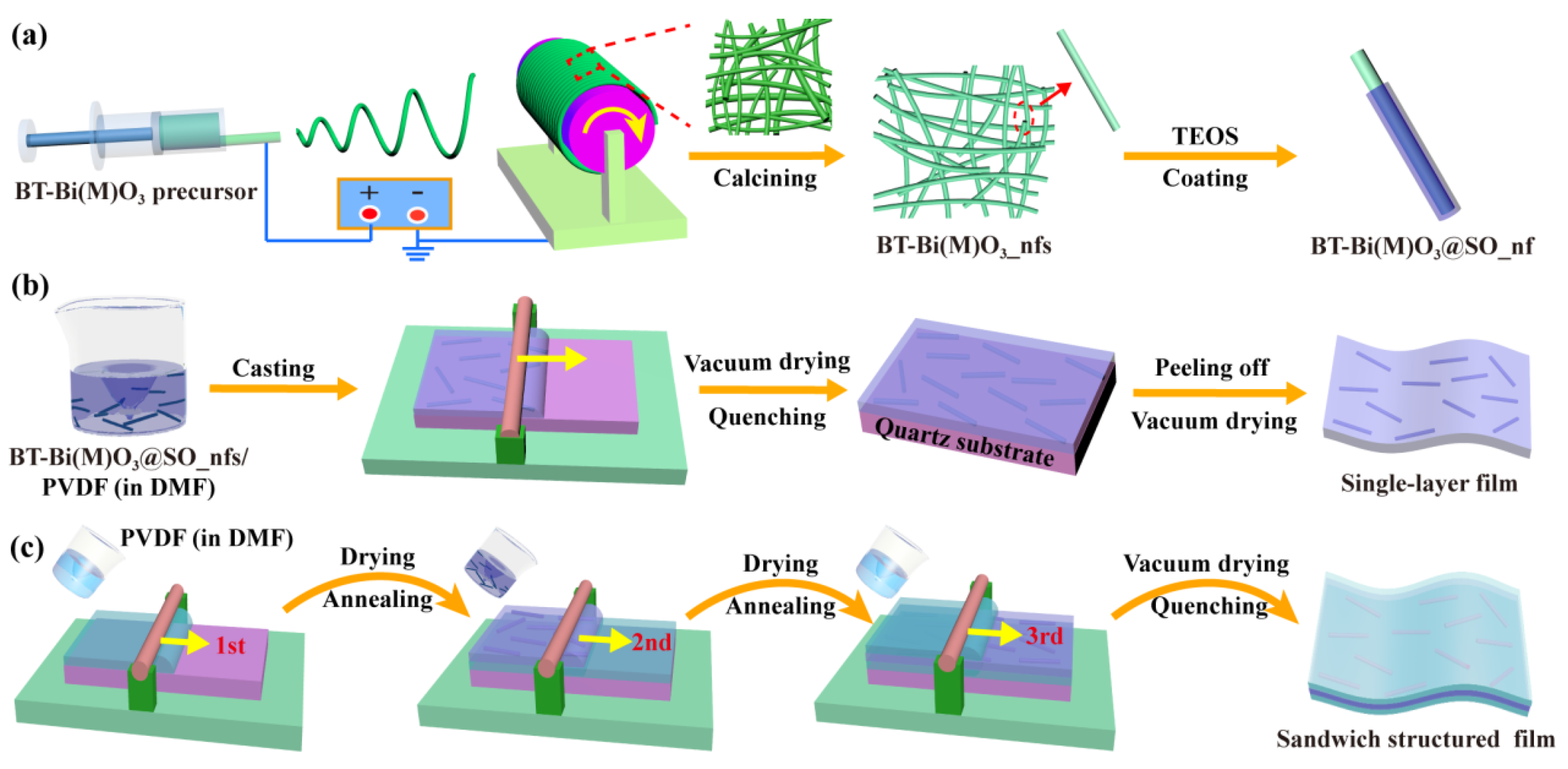
2.2. Preparation of BT-Bi(M)O3_nfs via Electrospinning

To prepare the BT-BMZ precursor, 8.5 mmol of Ba(OH)2·8H2O, 1.5 mmol of Bi(CH3COO)3, and 0.75 mmol of Mg(OC2H5)2 powders were dissolved in 9 mL of acetic acid and magnetically stirred for 30 min to obtain a transparent solution (A). Next, 8.5 mmol of tetrabutyl titanate and 0.75 mmol of zirconium n-butoxide were added into a solution containing 3 mL of ethanol absolute and 1 mL of acetyl acetone and stirred to form a yellowish transparent solution (B). Solution A was added to solution B drop by drop under continuous stirring, and then 6 g of 20 wt% PVP acetic solution was added to adjust the viscosity of the solution. The obtained transparent solution was further stirred for 12 h before use. The procedure for preparing BT-BMT precursor was almost the same as above procedure. The electrospinning process was performed under an applied electric field of 1.2 kV/cm. The distance between the needle and collector was fixed at 15 cm, and an injection rate of 1.0 mL/h was adopted. The collected nonwoven fabric was vacuum-dried at 80 °C for 12 h and subsequently calcined at 750 °C for 3 h to obtain crystalline BT-Bi(M)O3_nfs.

2.3. Surface Coating of BT-Bi(M)O3_nfs with SiO2

BT-Bi(M)O3_nfs were coated with SiO2 (BT-Bi(M)O3@SO_nfs) via a modified Stöber method [20]. Typically, 0.75 g of BT-Bi(M)O3_nfs were dispersed in a mixture of 600 mL of 2-propanol, 100 mL of deionized water, and 15 mL of 25–28 wt% ammonia solution. Next, 1.4 mL of TEOS was added into the suspension under vigorous stirring. The suspension was further mechanically stirred for 3 h to ensure the homogeneous coating of SiO2. The obtained BT-Bi(M)O3@SO_nfs were washed with deionized water 5 times and collected via suction filtration. Before use, they were vacuum-dried at 80 °C for 12 h.

2.4. Fabrication of BT-Bi(M)O3@SO_nf/PVDF Nanocomposite Films

BT-Bi(M)O3@SO_nfs were ultrasonically dispersed in DMF. PVDF was then added in proportion. The obtained mixtures were stirred for 24 h and degassed in vacuum before use. Single-layer BT-Bi(M)O3@SO_nfs/PVDF nanocomposite films were fabricated via a solution casting method. Sandwich-structured PVDF/x wt% BT-Bi(M)O3@SO_nfs/PVDF/PVDF nanocomposite films (denoted as 0-x-0) were prepared layer by layer through solution casting. PVDF/6 wt% 0.85BaTiO3-0.15Bi(Mg0.5Zr0.5)O3@SiO2 nanofiber/PVDF/PVDF nanocomposite films, the as-cast nanocomposite films, were then vacuum-dried at 80 °C for 12 h to remove DMF. Finally, the films were heated at 200 °C for 10 min, immediately quenched in an ice-water bath, and then peeled off of the quartz substrates and vacuum-dried at 60 °C for 12 h to remove residual moisture.

2.5. Finite Element Analysis of Electric Field Distribution

The local electric field distribution in the nanocomposite films was numerically simulated using COMSOL Multiphysics software (Version 5.3a). For convenience, the inner and outer diameters of BT-BMT@SO_nfs were set as 100 nm and 150 nm, respectively; and for BT-BMZ@SO_nfs they were set as 125 nm and 150 nm, respectively, so that their total diameters were equal. The length of the nanofibers was set as ~2.6 μm. The dielectric constants of BT-BMT, BT-BMZ, SiO2, and PVDF were set as 1300 [17,21], 900 [22,23], 4, and 9, respectively. An electric field of 300 MV/m was applied on the models.

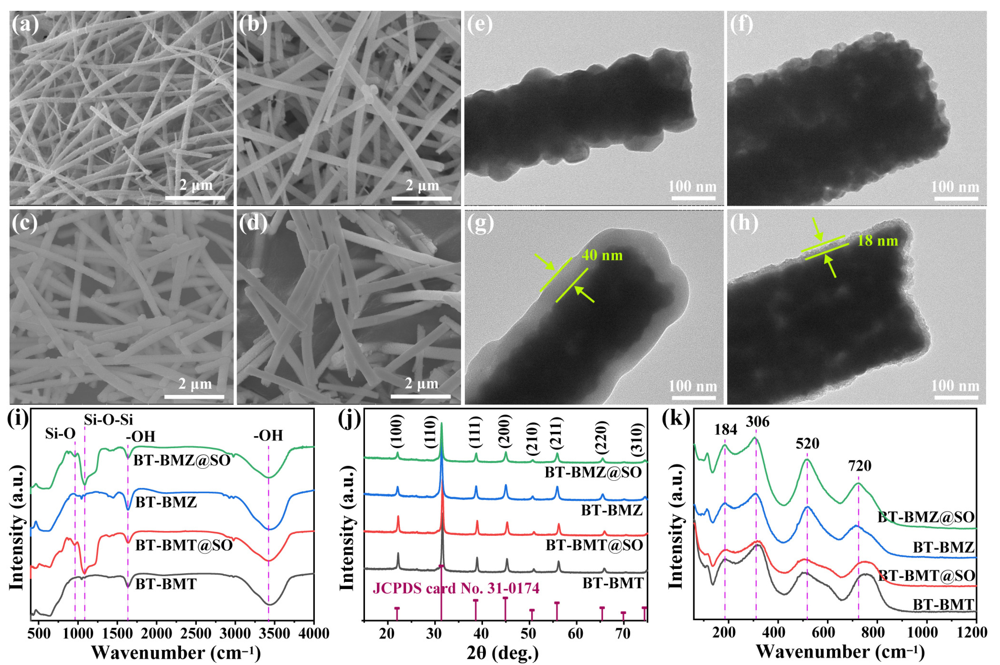
2.6. Characterization
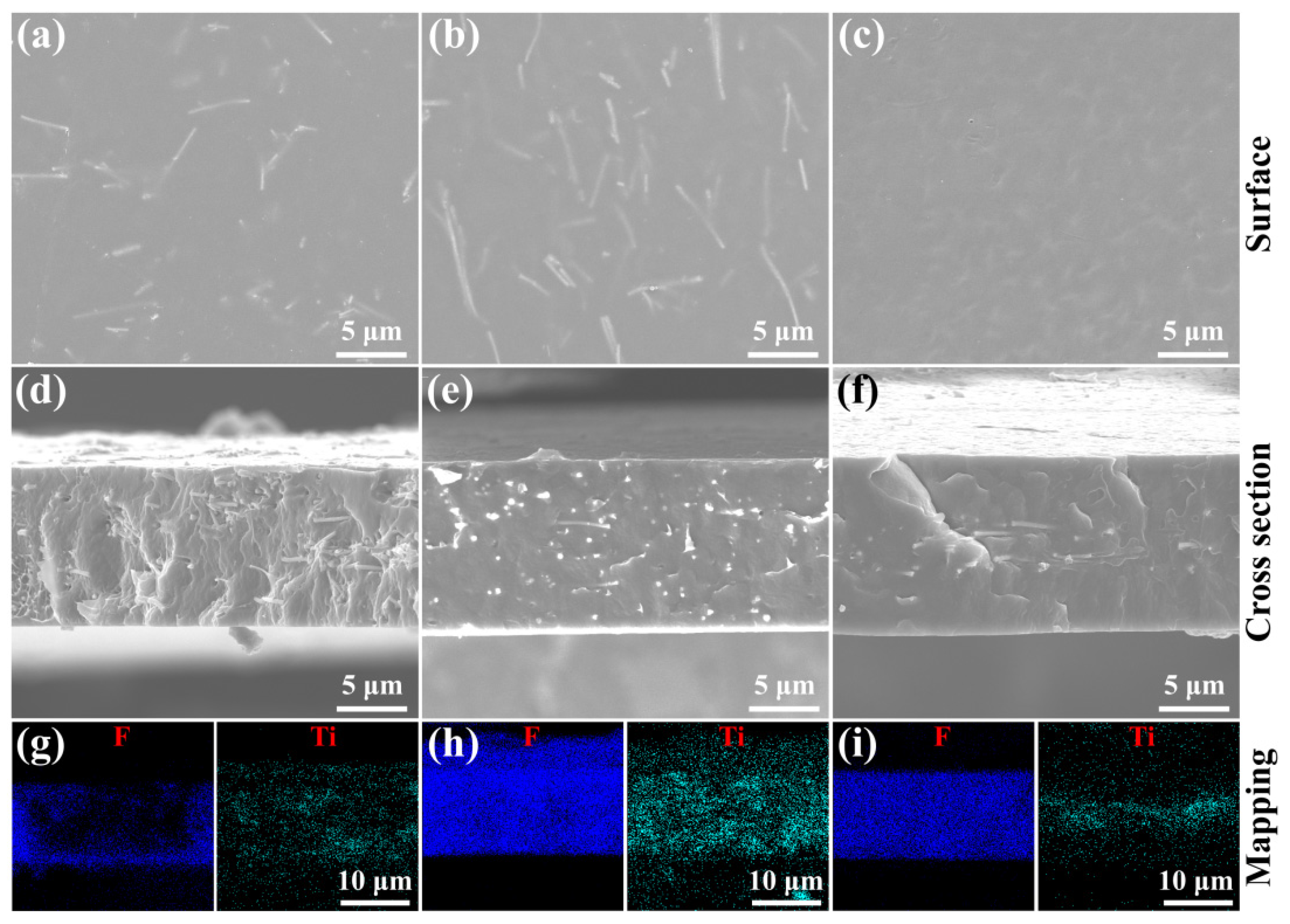
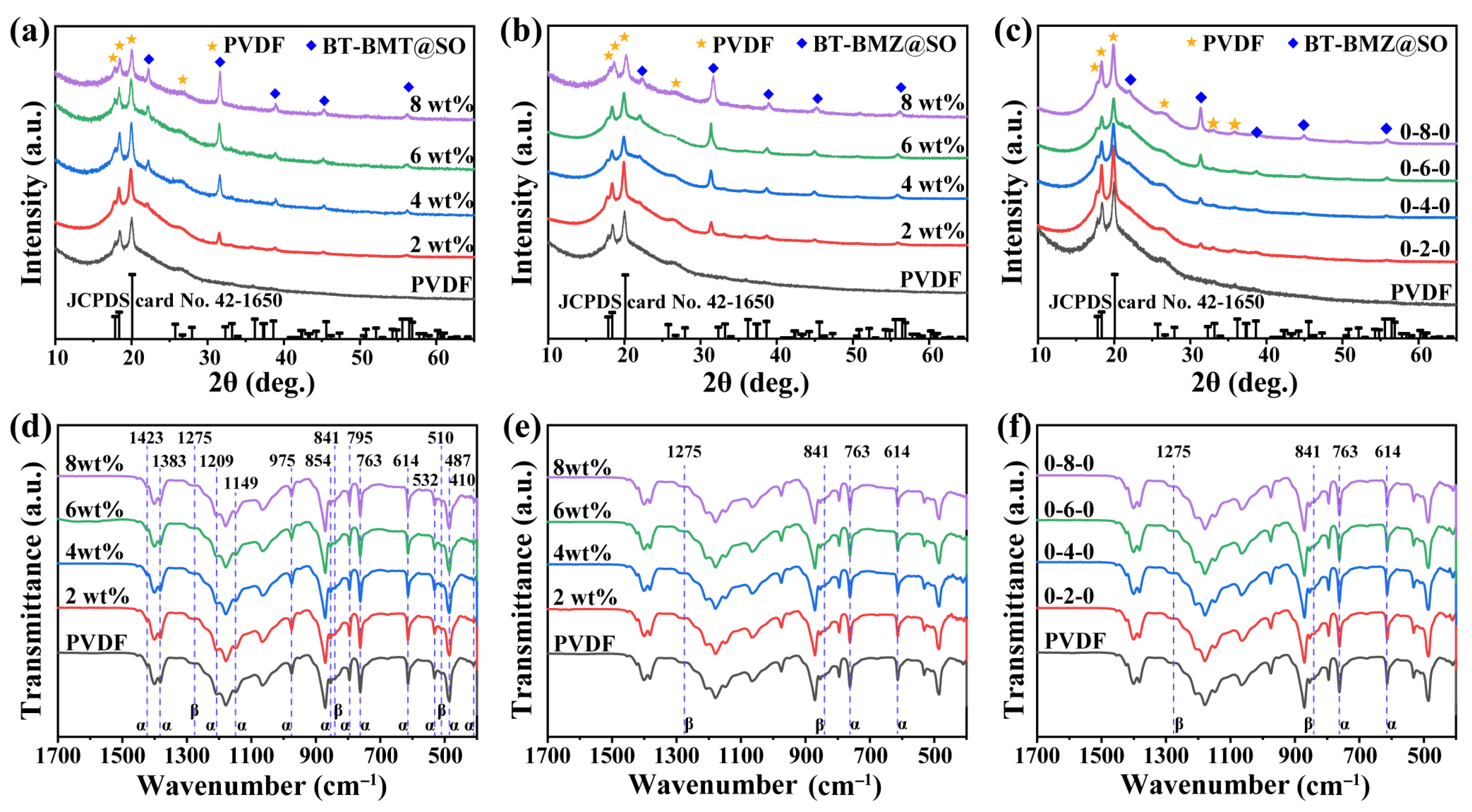
A scanning electron microscope (Nova Nano SEM 450, Hillsboro, OR, USA) and a transmission electron microscope (HT7700 EXALENS, Chiyoda City, Japan) were used to observe morphologies. An X-ray powder diffractometer with Cu Kα radiation (XRD, SmartLab 9KW, Rigaku, Tokyo, Japan) was used to identify phase structures. Raman spectroscopy was recorded on an inVia Qontor spectrometer (Gloucestershire, UK). Fourier-transform infrared (FTIR) spectroscopy was recorded using a FT/IR-6700 spectrophotometer (Tokyo, Japan). For the measurement of room-temperature dielectric and electrical properties, gold electrodes with a diameter of 3 mm were sputtered on both sides of nanocomposite films. Dielectric properties were tested using a precision impedance analyzer (Agilent Technologies 4294A, Santa Clara, CA, USA) at 1 Vrms. Breakdown strength was tested in silicone using a Changsheng 2674BX dielectric withstand voltage test system (Nanjing, China). The PE loop was measured at 10 Hz using a Radiant Premier II ferroelectric test system (Los Angeles, CA, USA).

3. Results

BT-Bi(M)O3_nfs were prepared via electrospinning, followed by calcining at 750 °C for crystallization (Figure 1a). Crystalline BT-Bi(M)O3_nfs showed large aspect ratios (Figure 2a,b). BT-BMT_nfs showed a lower average diameter than BT-BMZ_nfs did; these were 184 nm and 267 nm, respectively (Figure S2a,b). To improve electric insulation properties, SiO2 was coated onto BT-Bi(M)O3_nfs via a modified Stöber method [20]. After coating, the average diameters of BT-BMT@SO_nfs and BT-BMZ@SO_nfs increased to 277 nm and 318 nm, respectively (Figure 2c,d and Figure S2c,d). Thus, the calculated SiO2 shell thicknesses of BT-BMT@SO_nfs and BT-BMZ@SO_nfs were around 46 nm and 25 nm, respectively. TEM images clearly display the SiO2 coating layers on BT-BMT@SO_nfs and BT-BMZ@SO_nfs and verify their thickness differences (Figure 2e–h). FTIR spectra further identify the successful coating of SiO2 (Figure 2i). Compared with BT-Bi(M)O3_nfs, two new bands at 960 cm−1 and 1087 cm−1 appeared in BT-Bi(M)O3@SO_nfs, which were assigned to the bending vibration of Si–OH and the tensile vibration of Si–O–Si, respectively. The highly insulating SiO2 layer enhanced the Eb of ceramic/polymer nanocomposites [24,25].
XRD patterns of the nanofibers are shown in Figure 2j, illustrating these materials as solid solutions with a perovskite structure. The diffraction peaks of BT-BMT_nfs are at higher angle positions than those of BT-BMZ_nfs, indicating their smaller unit cells. This result is consistent with previous studies, which found the expansion and shrinkage of unit cells in BT-BMZ and BT-BMT compared with BT (JCPDS card No. 31-0174), respectively [17,23]. The XRD peaks of BT-Bi(M)O3@SO_nfs were the same as those of corresponding BT-Bi(M)O3_nfs, indicating the SiO2 layers were amorphous. Splitting of the (002) peak could not be observed in all samples, indicating the absence of non-cubic distortions. Raman measurement was performed to further study their local structures (Figure 2k). The absence of a 270 cm−1 peak and the existence of a 720 cm−1 peak verified their local short-range order structures rather than long-range order structures. Compared with BT-BMZ_nfs, Raman peaks located at 306 cm−1, 520 cm−1, and 720 cm−1 broadened in BT-BMT_nfs. This was because many more ions like Bi3+ and Mg2+ entered the BT crystal lattices, resulting in the short-range polarization mismatch, and consequently leading to the broadening of Raman peaks. BT-BMT and BT-BMZ ceramics without long-range ferroelectricity ordering usually show relaxor ferroelectricity [17,23].
Single-layer BT-Bi(M)O3@SO_nf/PVDF nanocomposite films were prepared via a facile solution casting method (Figure 1b). Sandwich-structured BT-BMZ@SO_nf/PVDF nanocomposite films were prepared layer by layer through solution casting (Figure 1c). Their thicknesses were well controlled by the scraper, ranging from 11–16 μm (Figure 3d–f). For single-layer films, BT-Bi(M)O3@SO_nfs could be observed in both surface and cross-sectional SEM images (Figure 3a,b,d,e). Moreover, their element mappings show that Ti and F elements shared similar distribution states (Figure 3g,h). These results reveal that BT-Bi(M)O3@SO_nfs homogeneously disperse in the whole single-layer films. For the sandwich-structured film, BT-BMZ@SO_nfs could only be observed in cross-sectional SEM images (Figure 3c,f and Figure S3). Moreover, the Ti element was predominantly distributed in the middle layer of these films, contrasting with the distribution state of the F element (Figure 3i). These results indicate that BT-BMZ@SO_nfs dispersed only in the middle layer of sandwich-structured films. In all these films, BT-Bi(M)O3@SO_nfs mainly oriented in the in-plane directions. No obvious defects, such as cracks and voids, could be observed; these features are beneficial breakdown properties.
XRD patterns (Figure 4a–c) and FTIR spectra (Figure 4d–f) of these nanocomposite films were also characterized to study their crystalline properties. For pristine PVDF, XRD peaks appeared at 2θ = 17.8°, 18.5°, 20.0°, and 26.6°, and were assigned to the (100), (020), (110), and (021) lattice planes of the α phase (JCPDS card No. 42-1650), respectively [26]. XRD peaks for all these nanocomposite films can be classified into two parts; i.e., those from α-phase PVDF and those from BT-Bi(M)O3@SO_nfs. Apart from the α phase, FTIR spectra clarified the existence of the β phase of PVDF in all samples. Absorption bands at 1423 cm−1, 1383 cm−1, 1209 cm−1, 1149 cm−1, 975 cm−1, 854 cm−1, 795 cm−1, 763 cm−1, 614 cm−1, 487 cm−1, and 410 cm−1 were assigned to the nonpolar α-phase PVDF [26]. And the absorption bands at 1275 cm−1, 841 cm−1, and 510 cm−1 were assigned to the polar β-phase PVDF. Absorbencies at 763 cm−1 and 841 cm−1 are usually utilized to calculate the relative amounts of these two phases according to the Lambert–Beer law [27,28]. The intensity of the band at 763 cm−1 was much stronger than that at 841 cm−1, indicating that the crystalline PVDF was dominated by the α phase. This result may account for the absence of XRD peaks of β-phase PVDF. Meanwhile, the intensities of these two bands remained almost unchanged as the filler content changed, suggesting BT-Bi(M)O3@SO_nfs had little effect on the relative contents of the α and β phases of crystalline PVDF.
Figure S4 shows the frequency-dependent dielectric properties of the nanocomposite films. Both the εr and dielectric loss (tan δ) of all films slightly decreased as the frequency increased from 102 Hz to 104 Hz, which was attributed to the suppressed interfacial polarization that occurred at elevated frequencies [29,30]. As the frequency further increased from 104 Hz to 106 Hz, the εr sharply decreased and the dielectric loss sharply increased, which was ascribed to the dipolar relaxation of PVDF at high frequencies [31].
Dielectric properties of the nanocomposite films at 1 kHz are summarized in Figure 5a. The εr of the three kinds of samples increased monotonically with increasing filler content. This result is in line with the effective medium theory that proposed that the introduction of high-εr ceramic nanofillers into polymer matrices could enhance their εr [8]. With the same filler content, the εr and dielectric loss of single-layer BT-BMZ@SO_nf/PVDF nanocomposite films were lower than those of single-layer BT-BMT@SO_nf/PVDF nanocomposite films. This result is mainly ascribed to the fact that BT-BMZ ceramic has lower εr and dielectric loss than BT-BMT ceramic does [17,21,22,23]. The sandwich-structured BT-BMZ@SO_nf/PVDF nanocomposite films possessed the lowest εr because of their relatively low total filler content, which was around one third of that of corresponding single-layer nanocomposite films. Meanwhile, they possessed the lowest dielectric loss, which can mainly be attributed to the barrier effect of the sandwich structure [32,33]. Alternating current conductivities (σac) of the nanocomposite films were also tested (Figure S5). The sandwich-structured BT-BMZ@SO_nf/PVDF nanocomposite films showed the lowest values, at 1 kHz, among the three kinds of samples (Figure 5b).
Breakdown strength is a crucial parameter in determining the energy storage capability and operative electric field of dielectric materials. Breakdown properties of the nanocomposite films were evaluated by a two-parameter Weibull distribution function described as follows:
P E = 1 e x p ( ( E / E b ) β )
where P(E) refers to the cumulative probability of electric failure, E is the measured breakdown strength, Eb is the characteristic breakdown strength, and the Weibull modulus β evaluates the breakdown reliability. The Weibull plots and fitted lines of the measured breakdown strength of the nanocomposite films are shown in Figure S6. Their Eb and β values are summarized in Figure 5c. With the same filler content, the single-layer BT-BMT@SO_nf/PVDF and sandwich-structured BT-BMZ@SO_nf/PVDF nanocomposites possessed the lowest and highest Eb, respectively. Meanwhile, they also showed the lowest and highest β values, respectively, indicating the worst and the best reliability. That the sandwich-structured BT-BMZ@SO_nf/PVDF nanocomposites achieved the best overall breakdown properties might be ascribed to their lowest dielectric loss and σac.
The electric field distribution in three kinds of nanocomposite films was simulated using the finite element method (Figure 5d–i). The electric field in the middle layer of sandwich-structured BT-BMZ@SO_nf/PVDF films was less concentrated than that in the corresponding area of single-layer BT-BMZ@SO_nf/PVDF films (Figure 5f–i). This was because the middle nanocomposite layer had a higher εr than the outer pristine PVDF layers did, and thus bore a lower average electric field. The middle layer with alleviated electric field concentration could act as barrier for electrical treeing at the layer interfaces [31], resulting in enhanced Eb of sandwich-structured BT-BMZ@SO_nf/PVDF films.
Among the three kinds of samples, the local electric field concentration phenomenon in the single-layer BT-BMT@SO_nf/PVDF nanocomposite film was the weakest (Figure 5d,e), which was ascribed to the thickest SiO2 shell. However, the BT-BMT@SO_nf/PVDF nanocomposite films had the lowest Eb. To evaluate the effect of the BT-Bi(M)O3 core and SiO2 shell on breakdown properties, the breakdown strengths of BT-BMT_nf/PVDF and BT-BMZ_nfs/PVDF nanocomposite films were measured (Figure S7). Results show that the BT-BMT_nf/PVDF nanocomposite films had a much lower Eb and Weibull moduli than those of corresponding BT-BMZ_nf/PVDF nanocomposite films (Figure 6a,b). Results also show that the SiO2 shell could indeed enhance the Eb of BT-Bi(M)O3@SO_nf/PVDF nanocomposite films (Figure 6c,d). However, the breakdown properties were primarily determined by the BT-Bi(M)O3 core rather than the SiO2 shell.
According to the above analysis, it can be concluded that the intrinsic properties of nanofillers are the determining factors of the Eb of polymer-based nanocomposites, and that the SiO2 coating and film structure design are effective strategies to enhance their Eb.
P–E curves of the nanocomposite films were measured to evaluate their energy storage properties (Figure S8). For all samples, the increasing electric field induced increased Pmax and Pr, resulting in increased Ue, but decreased η (Figure 7a–c). Meanwhile, Ud also increased with the increasing electric field. At the same electric field, the Pr of the single-layer BT-BMT@SO_nf/PVDF nanocomposite films obviously increased when the filler content exceeded 2 wt%. As a result, their η sharply decreased, resulting in decreased Ud (Figure 7a). By comparison, the single-layer and sandwich-structured BT-BMZ@SO_nf/PVDF nanocomposite films showed much slimmer P–E curves, and hence higher η (Figure 7b,c). Although those films with different filler contents showed small differences in Ud under the same electric fields, they showed large differences in Umax because of Eb differences and the induced Pmax differences (Figure S8).
The 2 wt% BT-BMT@SO_nf/PVDF, 6 wt% BT-BMZ@SO_nf/PVDF, and 0-6-0 BT-BMZ@SO_nf/PVDF nanocomposite films possessed the largest Umax among the three kinds of nanocomposites, respectively. Their Umax and Eb are summarized in Figure 7d. The Umax of pristine PVDF and these three nanocomposite films were 5.2, 4.7, 8.4, and 11.1 J/cm3, with ηs of 65.1%, 68.1%, 68.0%, and 68.0%, respectively. Their differences in η were subtle, thus their large Umax differences can mainly be attributed to Eb differences and induced Pmax differences. Their Eb were 328, 288, 405, and 458 MV/m, with induced Pmax of 4.7, 4.6, 6.1, and 7.0 μC/cm2, respectively. A comparison of energy storage properties between the 0-6-0 BT-BMZ@SO_nf/PVDF nanocomposite films and recently reported PVDF-based nanocomposites with 1D fillers is depicted in Figure 7e [16,34,35,36,37,38,39,40,41,42,43,44,45,46,47]. It can be seen that the 0-6-0 BT-BMZ@SO_nf/PVDF nanocomposite films show better comprehensive energy storage properties than most representative nanocomposites.

4. Conclusions

Three kinds of polymer nanocomposites, single-layer BT-BMT@SO_nf/PVDF, single-layer BT-BMZ@SO_nf/PVDF, and sandwich-structured BT-BMZ@SO_nf/PVDF, were fabricated via a solution casting method. The comparison of their energy storage properties proves that Eb is a critical parameter for enhancing the Umax of polymer nanocomposites. The combination of simulated results and experimental results shows that a SiO2 coating can improve the breakdown properties of single-layer BT-Bi(M)O3_nf/PVDF nanocomposites, and that the components or the intrinsic properties of BT-Bi(M)O3 are the determining factors for their Eb. Although constructing sandwich-structured films sacrificed their εr to some extent, it was effective in enhancing their Eb, and consequently their Ud. As a result, the sandwich-structured 0-6-0 BT-BMZ@SO_nf/PVDF nanocomposite films achieved the best overall energy storage performance. Their Ud reached 11.1 J/cm3 at an Eb of 458 MV/m, which are ~2.15 and ~1.40 times those of pristine PVDF. Based on these results, two points should be emphasized to enhance the Ud of BaTiO3-Bi(M)O3@SiO2/PVDF nanocomposites: one is that the component of the nanofillers is a determining factor; the other is that the structural design of nanocomposite films is an effective strategy.

Supplementary Materials

The following supporting information can be downloaded at: https://www.mdpi.com/article/10.3390/nano15080569/s1, Figure S1: Schematic illustration of calculating storage energy density (Ue), discharge energy density (Ud), and efficiency (η) of non-linear dielectrics from a PE loop; Figure S2: Diameter distributions of (a) BT-BMT_nfs, (b) BT-BMZ_nfs, (c) BT-BMT@SO_nfs, and (d) BT-BMZ@SO_nfs; Figure S3: Cross-sectional SEM images of (a) 0-2-0, (b) 0-4-0, and (c) 0-6-0 sandwich-structured BT-Bi(M)O3@SO_nf/PVDF nanocomposite films; Figure S4: Frequency-dependent dielectric constants and dielectric losses of (a) single-layer BT-BMT@SO_nf/PVDF, (b) single-layer BT-BMZ@SO_nf/PVDF, and (c) sandwich-structured BT-BMZ@SO_nf/PVDF nanocomposite films; Figure S5: Alternating current conductivities of (a) single-layer BT-BMT@SO_nf/PVDF, (b) single-layer BT-BMZ@SO_nf/PVDF, and (c) sandwich-structured BT-BMZ@SO_nf/PVDF nanocomposite films; Figure S6: Weibull plots of breakdown strength of (a) single-layer BT-BMT@SO_nf/PVDF, (b) single-layer BT-BMZ_nf@SO_nf/PVDF, and (c) sandwich-structured BT-BMZ@SO_nf/PVDF nanocomposite films; Figure S7: Weibull plots of breakdown strength of (a) BT-BMT_nf/PVDF and (b) BT-BMZ_nf/PVDF nanocomposite films; Figure S8: P–E loops of (a) PVDF, (b–e) single-layer BT-BMT@SO_nf/PVDF, (f–i) single-layer BT-BMZ@SO_nf/PVDF, and (j–m) sandwich-structured BT-BMZ@SO_nf/PVDF nanocomposite films under different electric fields.

Author Contributions

Conceptualization, J.H. and F.L.; methodology, J.H.; validation, F.L.; formal analysis, J.H.; investigation, J.H. and F.L.; resources, F.L.; data curation, J.H.; writing—original draft preparation, J.H.; writing—review and editing, J.H. and F.L.; visualization, J.H.; supervision, F.L.; project administration, F.L.; funding acquisition, F.L. All authors have read and agreed to the published version of the manuscript.

Funding

This research was supported by the Science and Technology Innovation Program of Hunan Province (Grant No. 2021RC2066).

Data Availability Statement

Data are contained within the article and Supplementary Materials.

Conflicts of Interest

The authors declare no conflicts of interest.

References

  1. Li, Q.; Yao, F.Z.; Liu, Y.; Zhang, G.Z.; Wang, H.; Wang, Q. High-temperature dielectric materials for electrical energy storage. Annu. Rev. Mater. Res. 2018, 48, 219–243. [Google Scholar] [CrossRef]
  2. Feng, Y.; Zhou, Y.; Zhang, T.; Zhang, C.; Zhang, Y.; Zhang, Y.; Chen, Q.; Chi, Q. Ultrahigh discharge efficiency and excellent energy density in oriented core-shell nanofiber-polyetherimide composites. Energy Storage Mater. 2020, 25, 180–192. [Google Scholar] [CrossRef]
  3. Sun, L.; Shi, Z.; He, B.; Wang, H.; Liu, S.; Huang, M.; Shi, J.; Dastan, D.; Wang, H. Asymmetric trilayer all-polymer dielectric composites with simultaneous high efficiency and high energy density: A novel design targeting for advanced energy storage capacitors. Adv. Funct. Mater. 2021, 31, 2100280. [Google Scholar] [CrossRef]
  4. Chen, H.; Pan, Z.; Wang, W.; Chen, Y.; Xing, S.; Cheng, Y.; Ding, X.; Liu, J.; Zhai, J.; Yu, J. Ultrahigh discharge efficiency and improved energy density in polymer-based nanocomposite for high-temperature capacitors application. Compos. Part A Appl. Sci. Manuf. 2021, 142, 106266. [Google Scholar] [CrossRef]
  5. Tan, D.Q. Review of polymer-based nanodielectric exploration and film scale-up for advanced capacitors. Adv. Funct. Mater. 2019, 30, 1808567. [Google Scholar] [CrossRef]
  6. Zhang, T.; Zhao, X.; Zhang, C.; Zhang, Y.; Zhang, Y.; Feng, Y.; Chi, Q.; Chen, Q. Polymer nanocomposites with excellent energy storage performances by utilizing the dielectric properties of inorganic fillers. Chem. Eng. J. 2021, 408, 127314. [Google Scholar] [CrossRef]
  7. Yang, Z.; Wang, J.; Hu, Y.L.; Deng, C.Y.; Zhu, K.J.; Qiu, J.H. Simultaneously improved dielectric constant and breakdown strength of PVDF/Nd-BaTiO3 fiber composite films via the surface modification and subtle filler content modulation. Compos. Part A Appl. Sci. Manuf. 2020, 128, 105675. [Google Scholar] [CrossRef]
  8. Kim, P.; Doss, N.M.; Tillotson, J.P.; Hotchkiss, P.J.; Pan, M.J.; Marder, S.R.; Li, J.; Calame, J.P.; Perry, J.W. High energy density nanocomposites based on surface-modified BaTiO3 and a ferroelectric polymer. ACS Nano 2009, 3, 2581–2592. [Google Scholar] [CrossRef] [PubMed]
  9. Tang, H.; Lin, Y.; Andrews, C.; Sodano, H.A. Nanocomposites with increased energy density through high aspect ratio PZT nanowires. Nanotechnology 2011, 22, 015702. [Google Scholar] [CrossRef]
  10. Li, J.; Seok, S.I.; Chu, B.; Dogan, F.; Zhang, Q.; Wang, Q. Nanocomposites of ferroelectric polymers with TiO2 nanoparticles exhibiting significantly enhanced electrical energy density. Adv. Mater. 2009, 21, 217–221. [Google Scholar] [CrossRef]
  11. Hu, J.; Zhang, S.; Tang, B. Rational design of nanomaterials for high energy density dielectric capacitors via electrospinning. Energy Storage Mater. 2021, 37, 530–555. [Google Scholar]
  12. Zhang, H.; Marwat, M.A.; Xie, B.; Ashtar, M.; Liu, K.; Zhu, Y.; Zhang, L.; Fan, P.; Samart, C.; Ye, Z.G. Polymer matrix nanocomposites with 1D ceramic nanofillers for energy storage capacitor applications. ACS Appl. Mater. Interfaces 2019, 12, 1–37. [Google Scholar] [CrossRef] [PubMed]
  13. Wang, Y.; Yao, M.G.; Ma, R.; Yuan, Q.B.; Yang, D.S.; Cui, B.; Ma, C.R.; Liu, M.; Hu, D.W. Design strategy of barium titanate/polyvinylidene fluoride-based nanocomposite films for high energy storage. J. Mater. Chem. A 2020, 8, 884–917. [Google Scholar] [CrossRef]
  14. Bouharras, F.E.; Raihane, M.; Ameduri, B. Recent progress on core–shell structured BaTiO3@polymer/fluorinated polymers nanocomposites for high energy storage: Synthesis, dielectric properties and applications. Prog. Mater. Sci. 2020, 113, 100670. [Google Scholar] [CrossRef]
  15. Pan, Z.B.; Yao, L.M.; Zhai, J.W.; Yang, K.; Shen, B.; Wang, H.T. Ultrafast discharge and high-energy-density of polymer nanocomposites achieved via optimizing the structure design of barium titanates. ACS Sustain. Chem. Eng. 2017, 5, 4707–4717. [Google Scholar] [CrossRef]
  16. Li, Z.; Liu, F.; Yang, G.; Li, H.; Dong, L.; Xiong, C.; Wang, Q. Enhanced energy storage performance of ferroelectric polymer nanocomposites at relatively low electric fields induced by surface modified BaTiO3 nanofibers. Compos. Sci. Technol. 2018, 164, 214–221. [Google Scholar] [CrossRef]
  17. Yuan, Q.; Li, G.; Yao, F.Z.; Cheng, S.D.; Wang, Y.; Ma, R.; Mi, S.B.; Gu, M.; Wang, K.; Li, J.F.; et al. Simultaneously achieved temperature-insensitive high energy density and efficiency in domain engineered BaTiO3-Bi(Mg0.5Zr0.5)O3 lead-free relaxor ferroelectrics. Nano Energy 2018, 52, 203–210. [Google Scholar] [CrossRef]
  18. Beuerlein, M.A.; Kumar, N.; Usher, T.M.; Brown-Shaklee, H.J.; Raengthon, N.; Reaney, I.M.; Cann, D.P.; Jones, J.L.; Brennecka, G.L.; Green, D.J. Current understanding of structure–processing–property relationships in BaTiO3–Bi(M)O3 dielectrics. J. Am. Ceram. Soc. 2016, 99, 2849–2870. [Google Scholar] [CrossRef]
  19. Zhu, M.-X.; Yu, Q.-C.; Song, H.-G.; Chen, T.-X.; Chen, J.-M. Rational design of high-energy-density polymer composites by machine learning approach. ACS Appl. Energy Mater. 2021, 4, 1449–1458. [Google Scholar]
  20. Tang, H.; Zhou, Z.; Bowland, C.C.; Sodano, H.A. Synthesis of calcium copper titanate (CaCu3Ti4O12) nanowires with insulating SiO2 barrier for low loss high dielectric constant nanocomposites. Nano Energy 2015, 17, 302–307. [Google Scholar]
  21. Jiang, X.; Hao, H.; Zhang, S.; Lv, J.; Cao, M.; Yao, Z.; Liu, H. Enhanced energy storage and fast discharge properties of BaTiO3 based ceramics modified by Bi(Mg1/2Zr1/2)O3. J. Eur. Ceram. Soc. 2019, 39, 1103–1109. [Google Scholar] [CrossRef]
  22. Hu, Q.; Bian, J.; Jin, L.; Zhuang, Y.; Huang, Z.; Liu, G.; Shur, V.Y.; Xu, Z.; Wei, X. Debye-like relaxation behavior and electric field induced dipole re-orientation of the 0.6BaTiO3-0.4Bi(Mg1/2Ti1/2)O3 ceramic. Ceram. Int. 2018, 44, 922–930. [Google Scholar] [CrossRef]
  23. Hu, Q.; Tian, Y.; Zhu, Q.; Bian, J.; Jin, L.; Du, H.; Alikin, D.O.; Shur, V.Y.; Feng, Y.; Xu, Z.; et al. Achieve ultrahigh energy storage performance in BaTiO3-Bi(Mg1/2Ti1/2)O3 relaxor ferroelectric ceramics via nano-scale polarization mismatch and reconstruction. Nano Energy 2019, 67, 104264. [Google Scholar] [CrossRef]
  24. Bi, K.; Bi, M.H.; Hao, Y.N.; Luo, W.; Cai, Z.M.; Wang, X.H.; Huang, Y.H. Ultrafine core-shell BaTiO3@SiO2 structures for nanocomposite capacitors with high energy density. Nano Energy 2018, 51, 513–523. [Google Scholar] [CrossRef]
  25. Xie, B.; Wang, Q.; Zhang, Q.; Liu, Z.; Lu, J.; Zhang, H.; Jiang, S. High energy storage performance of PMMA nanocomposites utilizing hierarchically structured nanowires based on interface engineering. ACS Appl. Mater. Interfaces 2021, 13, 27382–27391. [Google Scholar] [CrossRef] [PubMed]
  26. Cai, X.; Lei, T.; Sun, D.; Lin, L. A critical analysis of the α, β and γ phases in poly(vinylidene fluoride) using FTIR. RSC Adv. 2017, 7, 15382–15389. [Google Scholar] [CrossRef]
  27. Zhu, C.; Yin, J.; Li, J.; Li, Y.; Zhao, H.; Yue, D.; Pan, L.; Wang, J.; Feng, Y.; Liu, X. Enhanced energy storage of polyvinylidene fluoride-based nanocomposites induced by high aspect ratio titania nanosheets. J. Appl. Polym. Sci. 2020, 138, 50244. [Google Scholar] [CrossRef]
  28. Ren, X.T.; Meng, N.; Zhang, H.; Wu, J.Y.; Abrahams, I.; Yan, H.X.; Bilotti, E.; Reece, M.J. Giant energy storage density in PVDF with internal stress polar nanostructures engineered. Nano Energy 2020, 72, 104662. [Google Scholar] [CrossRef]
  29. Xu, J.; Fu, C.; Chu, H.; Qian, J.; Li, W.; Ran, X.; Nie, W. Improved discharge energy density of poly(vinylidene fluoride)-based nanocomposites via a small amount of dopamine-modified TiO2 nanosheets. J. Electron. Mater. 2021, 50, 4250–4260. [Google Scholar] [CrossRef]
  30. Nian, W.; Wang, Z.; Wang, T.; Xiao, Y.; Chen, H. Significantly enhanced breakdown strength and energy density in sandwich-structured NBT/PVDF composites with strong interface barrier effect. Ceram. Int. 2018, 44, S50–S53. [Google Scholar] [CrossRef]
  31. Guo, R.; Luo, H.; Yan, M.; Zhou, X.; Zhou, K.; Zhang, D. Significantly enhanced breakdown strength and energy density in sandwich-structured nanocomposites with low-level BaTiO3 nanowires. Nano Energy 2021, 79, 105412. [Google Scholar] [CrossRef]
  32. Ru, J.; Min, D.; Lanagan, M.; Li, S.; Chen, G. Enhanced energy storage properties of thermostable sandwich-structured BaTiO3/polyimide nanocomposites with better controlled interfaces. Mater. Des. 2021, 197, 109270. [Google Scholar] [CrossRef]
  33. Wang, Y.F.; Wang, L.X.; Yuan, Q.B.; Chen, J.; Niu, Y.J.; Xu, X.W.; Cheng, Y.T.; Yao, B.; Wang, Q.; Wang, H. Ultrahigh energy density and greatly enhanced discharged efficiency of sandwich-structured polymer nanocomposites with optimized spatial organization. Nano Energy 2018, 44, 364–370. [Google Scholar] [CrossRef]
  34. Xu, J.; Fu, C.; Chu, H.; Wu, X.; Tan, Z.; Qian, J.; Li, W.; Song, Z.; Ran, X.; Nie, W. Enhanced energy density of PVDF-based nanocomposites via a core–shell strategy. Sci. Rep. 2020, 10, 17084. [Google Scholar] [CrossRef]
  35. Zhang, Y.; Chi, Q.; Liu, L.; Zhang, T.; Zhang, C.; Chen, Q.; Wang, X.; Lei, Q. PVDF-Based dielectric composite films with excellent energy storage performances by design of nanofibers composition gradient structure. ACS Appl. Energy Mater. 2018, 1, 6320–6329. [Google Scholar] [CrossRef]
  36. Lin, X.; Hu, P.; Jia, Z.; Gao, S. Enhanced electric displacement induces large energy density in polymer nanocomposites containing core–shell structured BaTiO3@TiO2 nanofibers. J. Mater. Chem. A 2016, 4, 2314–2320. [Google Scholar] [CrossRef]
  37. Wang, G.; Huang, Y.; Wang, Y.; Jiang, P.; Huang, X. Substantial enhancement of energy storage capability in polymer nanocomposites by encapsulation of BaTiO3 NWs with variable shell thickness. Phys. Chem. Chem. Phys. 2017, 19, 21058–21068. [Google Scholar] [CrossRef]
  38. Liu, S.; Xue, S.; Shen, B.; Zhai, J. Reduced energy loss in poly(vinylidene fluoride) nanocomposites by filling with a small loading of core–shell structured BaTiO3/SiO2 nanofibers. Appl. Phys. Lett. 2015, 107, 032907. [Google Scholar] [CrossRef]
  39. Yao, L.M.; Pan, Z.B.; Zhai, J.W.; Zhang, G.Z.; Liu, Z.Y.; Liu, Y.H. High-energy-density with polymer nanocomposites containing of SrTiO3 nanofibers for capacitor application. Compos. Part A Appl. Sci. Manuf. 2018, 109, 48–54. [Google Scholar] [CrossRef]
  40. Liu, S.H.; Wang, J.; Shen, B.; Zhai, J.W.; Hao, H.S.; Zhao, L.M. Poly(vinylidene fluoride) nanocomposites with a small loading of core–shell structured BaTiO3@Al2O3 nanofibers exhibiting high discharged energy density and efficiency. J. Alloys Compd. 2017, 696, 136–142. [Google Scholar] [CrossRef]
  41. Pan, Z.B.; Yao, L.M.; Ge, G.L.; Shen, B.; Zhai, J.W. High-performance capacitors based on NaNbO3 nanowires/poly(vinylidene fluoride) nanocomposites. J. Mater. Chem. A 2018, 6, 14614–14622. [Google Scholar] [CrossRef]
  42. Pan, Z.; Yao, L.; Zhai, J.; Fu, D.; Shen, B.; Wang, H. High-energy-density polymer nanocomposites composed of newly structured one-dimensional BaTiO3@Al2O3 nanofibers. ACS Appl. Mater. Interfaces 2017, 9, 4024–4033. [Google Scholar] [CrossRef] [PubMed]
  43. Zhang, H.; Zhu, Y.; Li, Z.; Fan, P.; Ma, W.; Xie, B. High discharged energy density of polymer nanocomposites containing paraelectric SrTiO3 nanowires for flexible energy storage device. J. Alloys Compd. 2018, 744, 116–123. [Google Scholar] [CrossRef]
  44. Xue, J.; Zhang, T.; Zhang, C.; Zhang, Y.; Feng, Y.; Zhang, Y.; Chi, Q. Excellent energy storage performance for P(VDF-TrFE-CFE) composites by filling core–shell structured inorganic fibers. J. Mater. Sci. Mater. Electron. 2020, 31, 21128–21141. [Google Scholar] [CrossRef]
  45. Hu, J.; Liu, Y.; Zhang, S.; Tang, B. Novel designed core–shell nanofibers constituted by single element-doped BaTiO3 for high-energy-density polymer nanocomposites. Chem. Eng. J. 2022, 428, 131046. [Google Scholar] [CrossRef]
  46. Cui, Y.; Zhang, T.; Feng, Y.; Zhang, C.; Chi, Q.; Zhang, Y.; Chen, Q.; Wang, X.; Lei, Q. Excellent energy storage density and efficiency in blend polymer-based composites by design of core-shell structured inorganic fibers and sandwich structured films. Compos. Part B Eng. 2019, 177, 107429. [Google Scholar] [CrossRef]
  47. Chi, Q.; Wang, X.; Zhang, C.; Chen, Q.; Chen, M.; Zhang, T.; Gao, L.; Zhang, Y.; Cui, Y.; Wang, X.; et al. High energy storage density for poly(vinylidene fluoride) composites by introduced core–shell CaCu3Ti4O12@Al2O3 nanofibers. ACS Sustain. Chem. Eng. 2018, 6, 8641–8649. [Google Scholar] [CrossRef]
Figure 1. Schematic illustrations of preparing (a) BT-Bi(M)O3@SO_nfs, (b) single-layer, and (c) sandwich-structured BT-Bi(M)O3@SO_nf/PVDF nanocomposite films.
Nanomaterials 15 00569 g001
Figure 2. SEM images of (a) BT-BMT_nfs, (b) BT-BMZ_nfs, (c) BT-BMT@SO_nfs, and (d) BT-BMZ@SO_nfs; TEM images of (e) BT-BMT_nfs, (f) BT-BMZ_nfs, (g) BT-BMT@SO_nfs, and (h) BT-BMZ@SO_nfs; (i) FT-IR spectra, (j) XRD patterns, and (k) Raman spectra of these nanofibers.
Nanomaterials 15 00569 g002
Figure 3. Surface SEM images, cross-sectional SEM images, and element mappings of (a,d,g) 8 wt% BT-BMT@SO_nf/PVDF, (b,e,h) 8 wt% BT-BMZ@SO_nf/PVDF, and (c,f,i) 0-8-0 wt% BT-BMZ@SO_nf/PVDF nanocomposite films.
Nanomaterials 15 00569 g003
Figure 4. XRD patterns of (a) single-layer BT-BMT@SO/PVDF, (b) single-layer BT-BMZ@SO/PVDF, and (c) sandwich-structured BT-BMZ@SO/PVDF nanocomposite films; and FTIR spectra of (d) single-layer BT-BMT@SO/PVDF, (e) single-layer BT-BMZ@SO/PVDF, and (f) sandwich-structured BT-BMZ@SO/PVDF nanocomposite films.
Nanomaterials 15 00569 g004
Figure 5. (a) Dielectric constants and dielectric losses of the nanocomposite films at 1 kHz; (b) AC conductivities of the nanocomposite films at 1 kHz; (c) breakdown strengths and Weibull moduli of the nanocomposite films; finite element simulation of local electric field distribution for (d,e) single-layer BT-BMT@SO_nf/PVDF, (f,g) single-layer BT-BMZ@SO_nf/PVDF, and (h,i) sandwich-structured BT-BMZ@SO_nf/PVDF nanocomposite films.
Nanomaterials 15 00569 g005
Figure 6. Comparisons of (a) characteristic breakdown strengths and (b) shape parameters between BT-BMT_nf/PVDF and BT-BMZ_nf/PVDF nanocomposite films; and comparisons of characteristic breakdown strengths between (c) BT-BMT_nf/PVDF and BT-BMT@SO_nf/PVDF and (d) BT-BMZ_nf/PVDF and BT-BMZ@SO_nf/PVDF nanocomposite films.
Nanomaterials 15 00569 g006
Figure 7. Discharge energy densities and efficiencies of three kinds of nanocomposite films: (a) single-layer BT-BMT@SO_nf/PVDF, (b) single-layer BT-BMZ@SO_nf/PVDF, and (c) sandwich-structured BT-BMZ@SO_nf/PVDF. (d) Comparison of maximum discharge energy densities and corresponding efficiencies of three kinds of nanocomposite films. (e) Comparison of energy storage properties between 0-6-0 BT-BMZ@SO_nf/PVDF nanocomposite films and recently reported PVDF-based nanocomposites with 1D fillers [34,35,36,37,38,39,40,41,42,43,44,45,46,47].
Nanomaterials 15 00569 g007
Disclaimer/Publisher’s Note: The statements, opinions and data contained in all publications are solely those of the individual author(s) and contributor(s) and not of MDPI and/or the editor(s). MDPI and/or the editor(s) disclaim responsibility for any injury to people or property resulting from any ideas, methods, instructions or products referred to in the content.

