

Glancing Angle Deposited Nanostructured Tellurium Layer Against Dendrite Formation and Side Reactions in Aqueous Zn-Ion Battery Anode

 , , , and
Abstract
1. Introduction
2. Materials and Methods
2.1. Materials and Chemicals
2.2. Anode Preparation
2.3. Material Characterizations
2.4. Electrochemical Characterization
2.5. Image Processing
3. Results and Discussion
4. Conclusions
Supplementary Materials
Author Contributions
Funding
Data Availability Statement
Acknowledgments
Conflicts of Interest
References
- Obama, B. The irreversible momentum of clean energy. Science 2017, 355, 126–129. [Google Scholar] [CrossRef] [PubMed]
- Burroughs, W. Climate: Into the 21st Century; Cambridge University Press: Cambridge, UK, 2003. [Google Scholar]
- Singer, S.F. Unstoppable Global Warming: Every 1500 Years; Rowman & Littlefield: Lanham, MD, USA, 2006. [Google Scholar]
- Zhu, Z.; Jiang, T.; Ali, M.; Meng, Y.; Jin, Y.; Cui, Y.; Chen, W. Rechargeable batteries for grid scale energy storage. Chem. Rev. 2022, 122, 16610–16751. [Google Scholar] [CrossRef]
- Zhang, T.; Tang, Y.; Guo, S.; Cao, X.; Pan, A.; Fang, G.; Zhou, J.; Liang, S. Fundamentals and perspectives in developing zinc-ion battery electrolytes: A comprehensive review. Energy Environ. Sci. 2020, 13, 4625–4665. [Google Scholar] [CrossRef]
- Jia, X.; Liu, C.; Neale, Z.G.; Yang, J.; Cao, G. Active materials for aqueous zinc ion batteries: Synthesis, crystal structure, morphology, and electrochemistry. Chem. Rev. 2020, 120, 7795–7866. [Google Scholar] [CrossRef]
- Zhang, Q.; Luan, J.; Tang, Y.; Ji, X.; Wang, H. Interfacial design of dendrite-free zinc anodes for aqueous zinc-ion batteries. Angew. Chem. Int. Ed. 2020, 59, 13180–13191. [Google Scholar] [CrossRef] [PubMed]
- Liu, J.; Xu, C.; Chen, Z.; Ni, S.; Shen, Z.X. Progress in aqueous rechargeable batteries. Green Energy Environ. 2018, 3, 20–41. [Google Scholar] [CrossRef]
- Blanc, L.E.; Kundu, D.; Nazar, L.F. Scientific challenges for the implementation of Zn-ion batteries. Joule 2020, 4, 771–799. [Google Scholar] [CrossRef]
- Song, M.; Tan, H.; Chao, D.; Fan, H.J. Recent advances in Zn-ion batteries. Adv. Funct. Mater. 2018, 28, 1802564. [Google Scholar] [CrossRef]
- Lemoine, K.; Hémon-Ribaud, A.; Leblanc, M.; Lhoste, J.; Tarascon, J.-M.; Maisonneuve, V. Fluorinated materials as positive electrodes for Li- and Na-ion batteries. Chem. Rev. 2022, 122, 14405–14439. [Google Scholar] [CrossRef]
- Fan, E.; Li, L.; Wang, Z.; Lin, J.; Huang, Y.; Yao, Y.; Chen, R.; Wu, F. Sustainable recycling technology for Li-ion batteries and beyond: Challenges and future prospects. Chem. Rev. 2020, 120, 7020–7063. [Google Scholar] [CrossRef]
- Cai, T.; Wahyudi, W.; Kumar, P.; Ma, Z.; Sun, Q.; Xie, H.; Wang, Y.; Zhao, F.; Cao, Z.; Cavallo, L.; et al. Overlooked challenges of interfacial chemistry upon developing high energy density silicon anodes for lithium-ion batteries. Mater. Sci. Eng. R Rep. 2024, 161, 100854. [Google Scholar] [CrossRef]
- Li, M.; Lu, J.; Chen, Z.; Amine, K. 30 years of lithium-ion batteries. Adv. Mater. 2018, 30, 1800561. [Google Scholar] [CrossRef] [PubMed]
- Yang, Y.; Liu, C.; Lv, Z.; Yang, H.; Zhang, Y.; Ye, M.; Chen, L.; Zhao, J.; Li, C.C. Synergistic manipulation of Zn2+ ion flux and desolvation effect enabled by anodic growth of a 3D ZnF2 matrix for long-lifespan and dendrite-free Zn metal anodes. Adv. Mater. 2021, 33, 2007388. [Google Scholar] [CrossRef] [PubMed]
- Guo, X.; He, G. Opportunities and challenges of zinc anodes in rechargeable aqueous batteries. J. Mater. Chem. A 2023, 11, 11987–12001. [Google Scholar] [CrossRef]
- Kang, Z.; Wu, C.; Dong, L.; Liu, W.; Mou, J.; Zhang, J.; Chang, Z.; Jiang, B.; Wang, G.; Kang, F.; et al. 3D porous copper skeleton supported zinc anode toward high capacity and long cycle life zinc ion batteries. ACS Sustain. Chem. Eng. 2019, 7, 3364–3371. [Google Scholar] [CrossRef]
- Miao, Z.; Zhang, F.; Zhao, H.; Du, M.; Li, H.; Jiang, H.; Li, W.; Sang, Y.; Liu, H.; Wang, S. Tailoring Local Electrolyte Solvation Structure via a Mesoporous Molecular Sieve for Dendrite-Free Zinc Batteries. Adv. Funct. Mater. 2022, 32, 2111635. [Google Scholar] [CrossRef]
- Xie, X.; Liang, S.; Gao, J.; Guo, S.; Guo, J.; Wang, C.; Xu, G.; Wu, X.; Chen, G.; Zhou, J. Manipulating the ion-transfer kinetics and interface stability for high-performance zinc metal anodes. Energy Environ. Sci. 2019, 13, 503–510. [Google Scholar] [CrossRef]
- Zhang, L.; Zhang, B.; Zhang, T.; Li, T.; Shi, T.; Li, W.; Shen, T.; Huang, X.; Xu, J.; Zhang, X.; et al. Eliminating dendrites and side reactions via a multifunctional ZnSe protective layer toward advanced aqueous Zn metal batteries. Adv. Funct. Mater. 2021, 31, 2100186. [Google Scholar] [CrossRef]
- Zhang, Q.; Ma, Y.; Lu, Y.; Ni, Y.; Lin, L.; Hao, Z.; Yan, Z.; Zhao, Q.; Chen, J. Halogenated Zn2+ solvation structure for reversible Zn metal batteries. J. Am. Chem. Soc. 2022, 144, 18435–18443. [Google Scholar] [CrossRef]
- Yao, L.; Hou, C.; Liu, M.; Chen, H.; Zhao, Q.; Zhao, Y.; Wang, Y.; Liu, L.; Yin, Z.W.; Qiu, J.; et al. Ultra-stable Zn anode enabled by fiber-directed ion migration using mass-producible separator. Adv. Funct. Mater. 2023, 33, 2209301. [Google Scholar] [CrossRef]
- Tao, F.; Liu, Y.; Ren, X.; Wang, J.; Zhou, Y.; Miao, Y.; Ren, F.; Wei, S.; Ma, J. Different surface modification methods and coating materials of zinc metal anode. J. Energy Chem. 2022, 66, 397–412. [Google Scholar] [CrossRef]
- Yan, Z.; Xin, W.; Zhu, Z. Artificial interphase engineering to stabilize aqueous zinc metal anodes. Nanoscale 2021, 13, 19828–19839. [Google Scholar] [CrossRef]
- Han, Z.; Zhang, C.; Lin, Q.; Zhang, Y.; Deng, Y.; Han, J.; Wu, D.; Kang, F.; Yang, Q.; Lv, W. A protective layer for lithium metal anode: Why and how. Small Methods 2021, 5, 2001035. [Google Scholar] [CrossRef] [PubMed]
- Fan, L.; Li, X. Recent advances in effective protection of sodium metal anode. Nano Energy 2018, 53, 630–642. [Google Scholar] [CrossRef]
- Zhao, Y.; Yang, C.; Yu, Y. A review on covalent organic frameworks for rechargeable zinc-ion batteries. Chin. Chem. Lett. 2023, 35, 108865. [Google Scholar] [CrossRef]
- Kang, L.; Cui, M.; Jiang, F.; Gao, Y.; Luo, H.; Liu, J.; Liang, W.; Zhi, C. Nanoporous CaCO3 coatings enabled uniform zn stripping/plating for long-life zinc rechargeable aqueous batteries. Adv. Energy Mater. 2018, 8, 1801090. [Google Scholar] [CrossRef]
- Li, W.; Wang, K.; Cheng, S.; Jiang, K. A long-life aqueous Zn-ion battery based on Na3V2(PO4)2F3 cathode. Energy Storage Mater. 2018, 15, 14–21. [Google Scholar] [CrossRef]
- Lai, C.; Liao, Y.; Ku, H.; Jao, W.; Gull, S.; Chen, H.; Chou, J.; Hu, C. Enhancing Zinc Electrode Stability Through Pre-Desolvation and Accelerated Charge Transfer via a Polyimide Interface for Zinc-Ion Batteries. Small 2024, 20, e2401713. [Google Scholar] [CrossRef]
- An, Y.; Xu, B.; Tian, Y.; Shen, H.; Man, Q.; Liu, X.; Yang, Y.; Li, M. Reversible Zn electrodeposition enabled by interfacial chemistry manipulation for high-energy anode-free Zn batteries. Mater. Today 2023, 70, 93–103. [Google Scholar] [CrossRef]
- Cui, M.; Xiao, Y.; Kang, L.; Du, W.; Gao, Y.; Sun, X.; Zhou, Y.; Li, X.; Li, H.; Jiang, F.; et al. Quasi-isolated Au particles as heterogeneous seeds to guide uniform Zn deposition for aqueous zinc-ion batteries. ACS Appl. Energy Mater. 2019, 2, 6490–6496. [Google Scholar] [CrossRef]
- Gao, L.; Qin, L.; Wang, B.; Bao, M.; Cao, Y.; Duan, X.; Yang, W.; Yang, X.; Shi, Q. Highly-Efficient and Robust Zn Anodes Enabled by Sub-1-µm Zincophilic CrN Coatings. Small 2024, 20, 2308818. [Google Scholar] [CrossRef] [PubMed]
- Wei, B.; Zheng, J.; Abhishek; Liu, X.; Wu, J.; Qi, Z.; Hou, Z.; Wang, R.; Ma, J.; Gandi, A.N.; et al. Design principle of insulating surface protective layers for metallic Zn anodes: A case study of ZrO2. Adv. Energy Mater. 2024, 14, 2401018. [Google Scholar] [CrossRef]
- Li, B.; Xue, J.; Lv, X.; Zhang, R.; Ma, K.; Wu, X.; Dai, L.; Wang, L.; He, Z. A facile coating strategy for high stability aqueous zinc ion batteries: Porous rutile nano-TiO2 coating on zinc anode. Surf. Coat. Technol. 2021, 421, 127367. [Google Scholar] [CrossRef]
- Yu, N.; Li, Y.; She, W.; Li, H.; Chen, H.; Cheng, W.; Chen, J.; Liu, H.; Tu, Y.; Huang, Z.; et al. Binder-free sodium zinc phosphate protection layer enabled dendrite-free Zn metal anode. ACS Appl. Mater. Interfaces 2022, 14, 50827–50835. [Google Scholar] [CrossRef]
- Liang, Z.; Zhou, W.; Wang, W.; Chi, Y.; Liu, W.; Zhao, L.; Chen, W. In situ formation of Zn@ Ag resulted in uniform and dendrite-free zinc deposition for the zinc metal anode. J. Phys. Conf. Ser. 2024, 2840, 012024. [Google Scholar] [CrossRef]
- Dong, M.; Huang, S.; Yang, J.; Hou, X.; Chen, H. Two dimensional Bi2Te3 protective layer modified metal zinc surface to inhibit zinc dendrites in AZIBs. J. Alloys Compd. 2024, 1008, 176669. [Google Scholar] [CrossRef]
- Guisbiers, G.; Badradeen, E.; Arscott, S. Determination of the solid surface energy of tellurium dioxide. J. Phys. Chem. Solids 2024, 193, 112167. [Google Scholar] [CrossRef]
- Chen, J.; Liu, N.; Zhao, S.; Dong, W.; Lv, Z.; Wan, D.; Bi, H.; Huang, F. Zincophilic Tellurium Interface Layer Enables Fast Kinetics for Ultralow Overpotential and Highly Reversible Zinc Anode. Adv. Funct. Mater. 2024, 35, 2413495. [Google Scholar] [CrossRef]
- Zhang, Y.; Manaig, D.; Freschi, D.J.; Liu, J. Materials design and fundamental understanding of tellurium-based electrochemistry for rechargeable batteries. Energy Storage Mater. 2021, 40, 166–188. [Google Scholar] [CrossRef]
- Lee, S.; Je, Y.; Seok, B.; Kim, H.T.; Jo, Y.-R.; Oh, S.J.; Im, B.; Kim, D.G.; Chee, S.-S.; An, G.-H. Anode surface engineering of zinc-ion batteries using tellurium nanobelt as a protective layer for enhancing energy storage performance. J. Energy Chem. 2024, 92, 113–123. [Google Scholar] [CrossRef]
- Fu, Y.-C.; Lin, T.-Y.; Chen, Y.-Z. Te-hybridized zeolitic imidazolate frameworks-derived core-shell design toward dendrite-free Zn anode for long-term aqueous zinc-ion batteries. J. Colloid Interface Sci. 2023, 649, 471–480. [Google Scholar] [CrossRef] [PubMed]
- Lee, Y.-H.; Park, E.; Jeoun, Y.; Huh, S.-H.; Ahn, K.-S.; Sung, Y.-E.; Yu, S.-H. Rapid construction of a tellurium artificial interface to form a highly reversible zinc anode. EES Batter. 2025, 1, 195–207. [Google Scholar] [CrossRef]
- Liang, J.; Liu, Q.; Li, T.; Luo, Y.; Lu, S.; Shi, X.; Zhang, F.; Asiri, A.M.; Sun, X. Magnetron sputtering enabled sustainable synthesis of nanomaterials for energy electrocatalysis. Green Chem. 2021, 23, 2834–2867. [Google Scholar] [CrossRef]
- Patzig, C.; Karabacak, T.; Fuhrmann, B.; Rauschenbach, B. Glancing angle sputter deposited nanostructures on rotating substrates: Experiments and simulations. J. Appl. Phys. 2008, 104, 094318. [Google Scholar] [CrossRef]
- Saadi, N.S.; Hassan, L.B.; Sayem, S.M.; More, K.L.; Karabacak, T. Growth of zinc oxide nanowires by a hot water deposition method. Nanotechnology 2024, 36, 035601. [Google Scholar] [CrossRef]
- Mishra, M.; Barthwal, S.; Tak, B.R.; Singh, R. Temperature-driven perturbations in growth kinetics, structural and optical properties of NiO thin films. Phys. Status Solidi (a) 2021, 218, 2100241. [Google Scholar] [CrossRef]
- Karabacak, T.; Wang, G.-C.; Lu, T.-M. Physical self-assembly and the nucleation of three-dimensional nanostructures by oblique angle deposition. J. Vac. Sci. Technol. A 2004, 22, 1778–1784. [Google Scholar] [CrossRef]
- Steele, J.J.; Brett, M.J. Nanostructure engineering in porous columnar thin films: Recent advances. J. Mater. Sci. Mater. Electron. 2007, 18, 367–379. [Google Scholar] [CrossRef]
- Tsoi, S.; Fok, E.; Sit, J.C.; Veinot, J.G.C. Surface functionalization of porous nanostructured metal oxide thin films fabricated by glancing angle deposition. Chem. Mater. 2006, 18, 5260–5266. [Google Scholar] [CrossRef]
- Dolatshahi-Pirouz, A.; Jensen, T.; Vorup-Jensen, T.; Bech, R.; Chevallier, J.; Besenbacher, F.; Foss, M.; Sutherland, D. Synthesis of Functional nanomaterials via colloidal mask templating and glancing angle deposition (GLAD). Adv. Eng. Mater. 2010, 12, 899–905. [Google Scholar] [CrossRef]
- Sayem, S.M.; Hariharalakshmanan, R.K.; Badradeen, E.; Bourdo, S.E.; Karabacak, T. Influence of Substrate Location and Temperature Variation on the Growth of ZnO Nanorods Synthesized by Hot Water Treatment. Materials 2024, 17, 3716. [Google Scholar] [CrossRef] [PubMed]
- Karabacak, T.; Singh, J.P.; Zhao, Y.-P.; Wang, G.-C.; Lu, T.-M. Scaling during shadowing growth of isolated nanocolumns. Phys. Rev. B 2003, 68, 125408. [Google Scholar] [CrossRef]
- Tang, F.; Parker, T.; Li, H.-F.; Wang, G.-C.; Lu, T.-M. Unusual magnesium crystalline nanoblades grown by oblique angle vapor deposition. J. Nanosci. Nanotechnol. 2007, 7, 3239–3244. [Google Scholar] [CrossRef] [PubMed]
- Demirkan, M.; Trahey, L.; Karabacak, T. Low-density silicon thin films for lithium-ion battery anodes. Thin Solid Film. 2016, 600, 126–130. [Google Scholar] [CrossRef]
- Ozkan, T.; Demirkan, M.T.; Walsh, K.A.; Karabacak, T.; Polycarpou, A.A. Density modulated nanoporous tungsten thin films and their nanomechanical properties. J. Mater. Res. 2016, 31, 2011–2024. [Google Scholar] [CrossRef]
- Wu, L.; Zhang, Y.; Shang, P.; Dong, Y.; Wu, Z.-S. Redistributing Zn ion flux by bifunctional graphitic carbon nitride nanosheets for dendrite-free zinc metal anodes. J. Mater. Chem. A 2021, 9, 27408–27414. [Google Scholar] [CrossRef]
- Hu, Q.; Hu, J.; Ma, F.; Liu, Y.; Xu, L.; Li, L.; Zhang, S.; Liu, X.; Zhao, J.; Pang, H. Redistributing zinc-ion flux by work function chemistry toward stabilized and durable Zn metal batteries. Energy Environ. Sci. 2024, 17, 2554–2565. [Google Scholar] [CrossRef]
- Harrington, G.F.; Santiso, J. Back-to-Basics tutorial: X-ray diffraction of thin films. J. Electroceramics 2021, 47, 141–163. [Google Scholar] [CrossRef]
- He, J.; Chen, Y.; Lv, W.; Wen, K.; Wang, Z.; Zhang, W.; Li, Y.; Qin, W.; He, W. Three-dimensional hierarchical reduced graphene oxide/tellurium nanowires: A high-performance freestanding cathode for Li–Te batteries. ACS Nano 2016, 10, 8837–8842. [Google Scholar] [CrossRef]
- Sciammarella, P.V.; de Souza, M.A.; Guimarães, L.d.M.; da Silva, M.I.N.; Pérez, J.C.G.; Rizzi, L.G.; Araujo, E.N.D. Photoinduced growth of the crystalline phase of tellurium on a 1T′-MoTe2 matrix. J. Appl. Phys. 2024, 135, 025302. [Google Scholar] [CrossRef]
- Krug, P.; Wiktorska, K.; Kaczyńska, K.; Ofiara, K.; Szterk, A.; Kuśmierz, B.; Mazur, M. Sulforaphane-assisted preparation of tellurium flower-like nanoparticles. Nanotechnology 2019, 31, 055603. [Google Scholar] [CrossRef]
- Du, Y.; Qiu, G.; Wang, Y.; Si, M.; Xu, X.; Wu, W.; Ye, P.D. One-dimensional van der Waals material tellurium: Raman spectroscopy under strain and magneto-transport. Nano Lett. 2017, 17, 3965–3973. [Google Scholar] [CrossRef]
- Faraci, G.; Gibilisco, S.; Pennisi, A.R. Quantum confinement and thermal effects on the Raman spectra of Si nanocrystals. Phys. Rev. B 2009, 80, 193410. [Google Scholar] [CrossRef]
- Geoffrion, L.D.; Guisbiers, G. Quantum confinement: Size on the grill! J. Phys. Chem. Solids 2020, 140, 109320. [Google Scholar] [CrossRef]
- Yilmaz, E.; Tuğay, E.; Aktağ, A.; Yildiz, I.; Parlak, M.; Turan, R. Surface morphology and depth profile study of Cd1−xZnxTe alloy nanostructures. J. Alloys Compd. 2012, 545, 90–98. [Google Scholar] [CrossRef]
- Smyth, C.M.; Zhou, G.; Barton, A.T.; Wallace, R.M.; Hinkle, C.L. Controlling the Pd Metal Contact Polarity to Trigonal Tellurium by Atomic Hydrogen-Removal of the Native Tellurium Oxide. Adv. Mater. Interfaces 2021, 8, 2002050. [Google Scholar] [CrossRef]
- Detriche, S.; Vivegnis, S.; Vanhumbeeck, J.-F.; Felten, A.; Louette, P.; Renner, F.; Delhalle, J.; Mekhalif, Z. XPS fast depth profile of the native oxide layers on AISI 304, 316 and 430 commercial stainless steels and their evolution with time. J. Electron Spectrosc. Relat. Phenom. 2020, 243, 146970. [Google Scholar] [CrossRef]
- Hassan, L.B.; Saadi, N.S.; Karabacak, T. Hierarchically rough superhydrophobic copper sheets fabricated by a sandblasting and hot water treatment process. Int. J. Adv. Manuf. Technol. 2017, 93, 1107–1114. [Google Scholar] [CrossRef]
- Altay, B.N.; Ma, R.; Fleming, P.D.; Joyce, M.J.; Anand, A.; Chen, T.; Keskin, B.; Maddipatla, D.; Turkani, V.S.; Kotkar, P.R.; et al. Surface free energy estimation: A new methodology for solid surfaces. Adv. Mater. Interfaces 2020, 7, 1901570. [Google Scholar] [CrossRef]
- Saadi, N.; Alotaibi, K.; Hassan, L.; Smith, Q.; Watanabe, F.; Khan, A.A.; Karabacak, T. Enhancing the antibacterial efficacy of aluminum foil by nanostructuring its surface using hot water treatment. Nanotechnology 2021, 32, 325103. [Google Scholar] [CrossRef]
- Park, S.H.; Byeon, S.Y.; Park, J.-H.; Kim, C. Insight into the critical role of surface hydrophilicity for dendrite-free zinc metal anodes. ACS Energy Lett. 2021, 6, 3078–3085. [Google Scholar] [CrossRef]
- Chae, J.S.; Park, S.K.; Roh, K.C.; Park, H.S. Electrode materials for biomedical patchable and implantable energy storage devices. Energy Storage Mater. 2020, 24, 113–128. [Google Scholar] [CrossRef]
- Lu, W.; Xie, C.; Zhang, H.; Li, X. Inhibition of zinc dendrite growth in zinc-based batteries. ChemSusChem 2018, 11, 3996–4006. [Google Scholar] [CrossRef] [PubMed]
- Huang, T.; Xu, K.; Jia, N.; Yang, L.; Liu, H.; Zhu, J.; Yan, Q. Intrinsic interfacial dynamic engineering of zincophilic microbrushes via regulating zn deposition for highly reversible aqueous zinc ion battery. Adv. Mater. 2022, 35, 2205206. [Google Scholar] [CrossRef] [PubMed]
- Yang, Q.; Mo, F.; Liu, Z.; Ma, L.; Li, X.; Fang, D.; Chen, S.; Zhang, S.; Zhi, C. Activating C-coordinated iron of iron hexacyanoferrate for Zn hybrid-ion batteries with 10 000-cycle lifespan and superior rate capability. Adv. Mater. 2019, 31, 1901521. [Google Scholar] [CrossRef]
- Zhang, R.; Chen, X.; Chen, X.; Cheng, X.; Zhang, X.; Yan, C.; Zhang, Q. Lithiophilic sites in doped graphene guide uniform lithium nucleation for dendrite-free lithium metal anodes. Angew. Chem. 2017, 129, 7872–7876. [Google Scholar] [CrossRef]
- Zhao, K.; Wang, C.; Yu, Y.; Yan, M.; Wei, Q.; He, P.; Dong, Y.; Zhang, Z.; Wang, X.; Mai, L. Ultrathin surface coating enables stabilized zinc metal anode. Adv. Mater. Interfaces 2018, 5, 1800848. [Google Scholar] [CrossRef]
- Yi, J.; Liang, P.; Liu, X.; Wu, K.; Liu, Y.; Wang, Y.; Xia, Y.; Zhang, J. Challenges, mitigation strategies and perspectives in development of zinc-electrode materials and fabrication for rechargeable zinc–air batteries. Energy Environ. Sci. 2018, 11, 3075–3095. [Google Scholar] [CrossRef]
- Sun, L.; Wang, Y.; Duan, G.; Luo, B.; Zheng, S.; Huang, J.; Ye, Z. A zincophilic ion-conductive layer with the desolvation effect and oriented deposition behavior achieving superior reversibility of Zn metal anodes. J. Mater. Chem. A 2023, 11, 17188–17199. [Google Scholar] [CrossRef]
- Yan, H.; Han, C.; Li, S.; Liu, J.; Ren, J.; Yang, S.; Li, B. Adjusting zinc ion de-solvation kinetics via rich electron-donating artificial SEI towards high columbic efficiency and stable Zn metal anode. Chem. Eng. J. 2022, 442, 136081. [Google Scholar] [CrossRef]
- Chen, X.; Xie, X.; Ruan, P.; Liang, S.; Wong, W.-Y.; Fang, G. Thermodynamics and kinetics of conversion reaction in zinc batteries. ACS Energy Lett. 2024, 9, 2037–2056. [Google Scholar] [CrossRef]
- Wang, L.; Zhou, S.; Yang, K.; Huang, W.; Ogata, S.; Gao, L.; Pu, X. Screening Selection of Hydrogen Evolution-Inhibiting and Zincphilic Alloy Anode for Aqueous Zn Battery. Adv. Sci. 2024, 11, e2307667. [Google Scholar] [CrossRef] [PubMed]
- Liu, C.; Lu, Q.; Omar, A.; Mikhailova, D. A facile chemical method enabling uniform Zn deposition for improved aqueous Zn-ion batteries. Nanomaterials 2021, 11, 764. [Google Scholar] [CrossRef] [PubMed]


| Surface Modification Layers | Current Density (mA/cm2) | Areal Capacity (mAh/cm2) | Cycle Life (h) | Nucleation Overpotential (mV) | References |
|---|---|---|---|---|---|
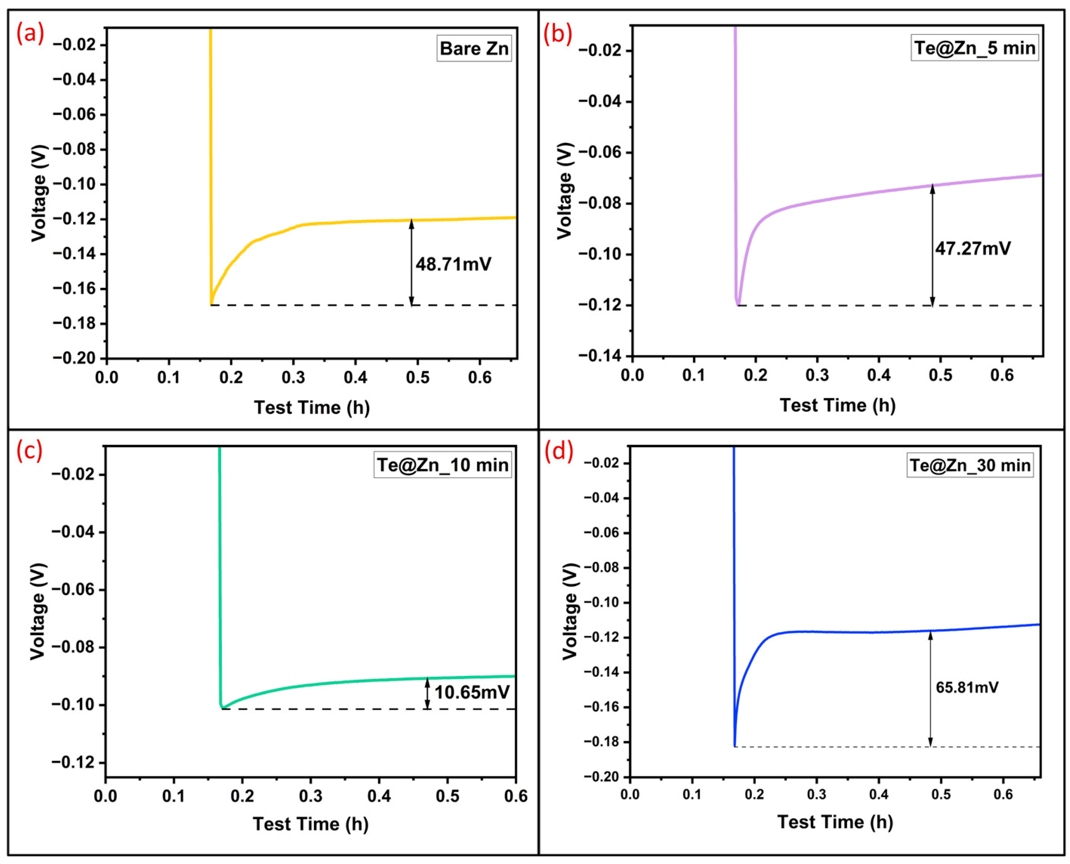
| TeNS layer | 1 | 0.5 | ~350 | 10.65 | This work |
| Cu layer | 1 | 1 | ~290 | 12 | [85] |
| Au layer | 0.25 | 0.05 | ~2000 | 111 | [32] |
| TiO2 layer | 1 | 1 | ~150 | 72.5 | [35] |
| Ag layer | 1 | 1 | ~1000 | 48 | [37] |
Disclaimer/Publisher’s Note: The statements, opinions and data contained in all publications are solely those of the individual author(s) and contributor(s) and not of MDPI and/or the editor(s). MDPI and/or the editor(s) disclaim responsibility for any injury to people or property resulting from any ideas, methods, instructions or products referred to in the content. |
© 2025 by the authors. Licensee MDPI, Basel, Switzerland. This article is an open access article distributed under the terms and conditions of the Creative Commons Attribution (CC BY) license (https://creativecommons.org/licenses/by/4.0/).
Share and Cite
Hussain, S.; Sayem, S.M.; Basurrah, A.; Rashed, T.; Watanabe, F.; Siraj, N.; Karabacak, T. Glancing Angle Deposited Nanostructured Tellurium Layer Against Dendrite Formation and Side Reactions in Aqueous Zn-Ion Battery Anode. Nanomaterials 2025, 15, 952. https://doi.org/10.3390/nano15120952
Hussain S, Sayem SM, Basurrah A, Rashed T, Watanabe F, Siraj N, Karabacak T. Glancing Angle Deposited Nanostructured Tellurium Layer Against Dendrite Formation and Side Reactions in Aqueous Zn-Ion Battery Anode. Nanomaterials. 2025; 15(12):952. https://doi.org/10.3390/nano15120952
Chicago/Turabian StyleHussain, Salim, S. M. Sayem, Assem Basurrah, Tahany Rashed, Fumiya Watanabe, Noureen Siraj, and Tansel Karabacak. 2025. "Glancing Angle Deposited Nanostructured Tellurium Layer Against Dendrite Formation and Side Reactions in Aqueous Zn-Ion Battery Anode" Nanomaterials 15, no. 12: 952. https://doi.org/10.3390/nano15120952
APA StyleHussain, S., Sayem, S. M., Basurrah, A., Rashed, T., Watanabe, F., Siraj, N., & Karabacak, T. (2025). Glancing Angle Deposited Nanostructured Tellurium Layer Against Dendrite Formation and Side Reactions in Aqueous Zn-Ion Battery Anode. Nanomaterials, 15(12), 952. https://doi.org/10.3390/nano15120952