Article

The Preparation of High-Performance MoO3 Nanorods for 2.1 V Aqueous Asymmetric Supercapacitor

School of Instrument and Electronics, North University of China, Taiyuan 030051, China
*
Authors to whom correspondence should be addressed.
Nanomaterials 2024, 14(24), 2029; https://doi.org/10.3390/nano14242029
Submission received: 29 October 2024 / Revised: 15 December 2024 / Accepted: 16 December 2024 / Published: 17 December 2024
(This article belongs to the Section Nanoelectronics, Nanosensors and Devices)

Abstract

:
In order to broaden the working voltage (1.23 V) of aqueous supercapacitors, a high-performance asymmetric supercapacitor with a working voltage window reaching up to 2.1 V is assembled using a nanorod-shaped molybdenum trioxide (MoO3) negative electrode and an activated carbon (AC) positive electrode, as well as a sodium sulfate–ethylene glycol ((Na2SO4-EG) electrolyte. MoO3 electrode materials are fabricated by adjusting the hydrothermal temperature, hydrothermal time and solution’s pH value. The specific capacity of the optimal MoO3 electrode material can reach as high as 244.35 F g−1 at a current density of 0.5 A g−1. For the assembled MoO3//AC asymmetric supercapacitor with a voltage window of 2.1 V, its specific capacity, the energy density, and the power density are 13.52 F g−1, 8.28 Wh kg−1, and 382.15 W kg−1 at 0.5 A g−1, respectively. Moreover, after 5000 charge–discharge cycles, the capacity retention rate of the device still reaches 109.2%. This is mainly attributed to the small particle size of MoO3 nanorods, which can expose more electrochemically active sites, thus greatly facilitating the transport of electrolyte ions, immersion at the electrolyte/electrolyte interface and the occurrence of electrochemical reactions.

1. Introduction

With the rapid development of the social economy, limited fossil fuel resources and the ever-increasing population have confronted mankind with energy issues. Supercapacitors (electrochemical capacitors) have drawn widespread attention due to advantages such as their high power density and long cycle life [1,2,3,4,5], making them highly promising candidates for the next-generation high-efficiency energy storage devices used in fields such as electronic devices, power quality systems, hybrid electric vehicles, and smart grids [6]. Compared with rechargeable batteries, the relatively low energy density of supercapacitors has seriously hindered their further commercial application. Therefore, a great deal of time has been devoted to researching how the energy density of supercapacitors can be improved while retaining their high power density and long cycle life. According to the energy density equation (E = CV2/2) [7], the energy density (E) of supercapacitors can be enhanced by either expanding the working voltage (V) or increasing the specific capacitance (C).
Supercapacitor electrolytes can effectively improve the working voltage (V). Electrolytes can be classified into non-aqueous electrolytes and aqueous electrolytes. In particular, non-aqueous electrolytes have become an attractive candidate in current applications due to their relatively wide working voltage, long cycle life, and high power density. However, they also have problems such as a high cost, relatively low ionic conductivity, and low safety. In recent years, aqueous electrolytes have attracted attention and been widely studied because of their advantages, which include a low cost, relatively high ionic conductivity, and high levels of safety [8,9]. Nevertheless, their low electrochemical stability window (1.23 V) has limited their practical application [10]. In terms of this issue, Alessio D’Alessandro and others have expanded the voltage window to 1.4 V by adding amino acids into the electrolyte [11]. Wang et al. designed and studied a cyano-substituted diquinoxaline phenazine (3CN-DPZ) organic electrode for aqueous alkaline ion batteries with a voltage of 2.0 V [12]. Liu et al. investigated 14M potassium formate and 6.4 m and 21 m cesium acetate, and achieved a high energy density and a battery voltage of up to 1.7 V [13].
Transition metal oxides usually have multiple oxidation states and can undergo reversible redox reactions, thereby providing a relatively high specific capacitance [14]. For example, manganese dioxide (MnO2 [15]), nickel oxide (NiO [16]), ferric oxide (Fe2O3 [17]), cobalt oxide (Co2O3 [18]), molybdenum trioxide (MoO3 [19]), etc., can store a large amount of charge through Faradaic pseudo-capacitance reactions within a certain potential range. This can promote the transmission of electrons in the electrode materials, reduce the internal resistance, and improve the power performance of supercapacitors. In addition, transition metal oxides usually possess good chemical and thermal stabilities. They can maintain the integrity of their structures during the charging and discharging processes, thus prolonging the service life of supercapacitors. Molybdenum, as a typical transition metal oxide, features multiple valence states and high electrochemical activity. Compounds of molybdenum, as electrochemical energy storage materials, have been widely researched and applied in both supercapacitor and lithium-ion battery materials.
As a transition metal oxide, MoO3 has a relatively high theoretical specific capacitance due to the multi-electron transfer process during the proton insertion–desorption process; it has thus attracted widespread attention as a pseudo-capacitor material applied to energy storage [20,21,22,23]. Additionally, the cathode needs to receive electrons at a lower potential for the reduction reaction during the charging/discharging process, and the redox potential of MoO3 is relatively low; therefore, the redox reaction of MoO3 can occur stably in this lower potential, resulting in more storage and the release of charge. The conversion process in the polyvalent state of MoO3 can result in the transfer of multiple electrons, so that the unit mass of MoO3 can store a relatively large amount of charge, thus providing a high theoretical capacity for the supercapacitor (1170 mAh g−1) [24,25]. Therefore, nanorod-shaped MoO3 can be selected as a cathode in this paper. Compared with crystalline MoO3, nanoscale MoO3 is highly favored because of its ordered structure, good chemical stability, high elasticity, low internal energy, and large surface area, enabling it to achieve isotropy [26].
Therefore, nanorod-shaped MoO3 was successfully prepared by a simple one-step hydrothermal method in this work. The optimal MoO3 material was obtained by adjusting the experimental conditions (hydrothermal time, hydrothermal temperature, and pH value). This nanostructure enables complete contact between the electrolyte and the active material, resulting in rapid reaction kinetics. The material prepared under the optimal conditions (180 °C/24 h/pH = 0.36) can reach a specific capacity of 244.35 F g−1 at a current density of 0.5 A g−1. In addition, an AC//MoO3 asymmetric supercapacitor was assembled with a Na2SO4-EG electrolyte, in which an aqueous electrolyte with a low salt concentration (1 M Na2SO4(mol kg⁻1)) was used, and the ethylene glycol (EG) was used as an additive. In this assembled device, due to the strong coordination between EG molecules and Na+ ions, some H2O molecules are not in the Na+ solvation shell and do not participate in the decomposition process on the electrode surface, thus achieving a wide electrochemical window (2.1 V) and demonstrating its application prospects in the field of energy storage devices.

2. Materials and Methods

2.1. Preparation

Analytically pure (99%) ammonium molybdate ((NH4)2MoO4) produced by Shanghai Macklin Biochemical Co., Ltd. (Shanghai, China); superfine-grade (65–68%) concentrated nitric acid produced by Shanghai Aladdin Biochemical Technology Co., Ltd. (Shanghai, China); analytically pure (99.7%) anhydrous ethanol produced by Sinopharm Chemical Reagent Co., Ltd. (Shanghai, China); analytically pure (99%) ethylene glycol produced by Shanghai Macklin Biochemical Co., Ltd. (Shanghai, China); polyvinylidene fluoride (PVDF) produced by Shanghai Aladdin Biochemical Technology Co., Ltd (Shanghai, China).; and capacitor-grade AC produced by Shanghai Aladdin Biochemical Technology Co., Ltd. (Shanghai, China) were obtained.
Preparation of MoO3 sample: The process of preparing MoO3 materials is shown in Figure 1. Firstly, 196 mg of (NH4)2MoO4 and 76 mL of pure water were put into a beaker subjected to magnetic stirring for one hour for later use. Then, a moderate amount (2.6 mL, 1.7 mL and 0.8 mL) of nitric acid (HNO3, 68%) was poured into the aforesaid solution to adjust the pH value (0.36, 0.58 or 0.84). Additionally, the hydrothermal time (12 h, 18 h, 24 h and 30 h) and hydrothermal temperature (160 °C, 180 °C and 200 °C) were used as the experimental variables for the hydrothermal reaction to obtain the optimal MoO3 sample; this was followed by centrifugation and freeze drying.
Preparation of electrode: Firstly, the 10 mg mL−1 ethanol–PVDF solution was prepared, and the prepared MoO₃ or activated carbon (AC) were dried and put on standby. Then, the MoO3 (AC), conductive carbon black and PVDF binder were mixed uniformly at a ratio of 8:1:1, and the electrode (MoO3 or AC) was obtained on a carbon cloth substrate; this was followed by drying at 70 °C for 12 h.
Preparation of the electrolyte: Firstly, 14.2 g of sodium sulfate powder (Na2SO4) and 100 mL of purified water were poured into the beaker and stirred overnight to obtain the transparent Na2SO4 electrolyte; then, 30 mL of ethylene glycol (EG) and 70 mL of the aforementioned Na2SO4 solution were mixed uniformly to prepare the Na2SO4-EG electrolyte.
Assembly of the supercapacitor: The MoO₃//AC asymmetric supercapacitor was assembled in an electrolytic cell by the MoO₃ negative electrode, AC positive electrode, and Na2SO4-EG electrolyte. In contrast, the MoO₃//AC asymmetric device with an Na2SO4 electrolyte was also fabricated to further explore the charge storage process of an asymmetric device with a Na2SO4-EG electrolyte.

2.2. Characterization

A field emission scanning electron microscope (SEM, Zeiss Merlin Compact from Jena, Germany) and X-ray energy-dispersive spectroscopy (EDS) were employed to characterize the microscopic morphology and elemental distribution of the samples. X-ray diffraction (XRD, PRO MPD from Utrecht, The Netherlands) was utilized to analyze the microscopic structure of the substances. A Fourier transform infrared (FT-IR) spectrometer (ThermoScientific NicoletiS20, Waltham, MA, USA) was used to analyze the molecular structure and information about the chemical bonds (functional groups) of the samples based on the position and intensity of the specific absorption peaks of chemical bonds or groups within the samples. The specific surface area and porosity of the electrode materials were characterized by employing the fully automatic specific surface area and porosity analyzer (Micromeritics ASAP 2460, Norcross, GA, USA).

2.3. Electrochemical Measurements

The electrochemical tests of the electrode materials were completed on the CHI760E electrochemical workstation (Shanghai, China). A three-electrode testing system was adopted, with the prepared electrode sheet used as the working electrode, the platinum electrode used as the counter electrode, and the saturated calomel electrode used as the reference electrode. A 1 mol/L Na2SO4 solution was used as the electrolyte. All the electrochemical tests were carried out at room temperature. Cyclic voltammetry tests (CV), galvanostatic charge–discharge tests (GCD), and electrochemical impedance spectroscopy tests (EIS) were used to test and compare the electrode materials prepared at different hydrothermal temperatures (160 °C, 180 °C, 200 °C), different pH values, and different hydrothermal times (12 h, 18 h, 24 h, 30 h). The voltage window for CV and GCD was −1 V to −0.3 V. According to the GCD curve, the formula for calculating the specific capacity is as follows:
C = I d V d t = I V d t V 1 V 2 V d V
In the formula, C, I, V, V1, V2 and t represent the specific capacitance (unit: F·g−1), applied current density (unit: A·g−1), working voltage window (unit: V), initial voltage (unit: V), cut-off voltage (unit: V) and discharge time (unit: s), respectively.
The formula for calculating the loading mass of the positive and negative electrodes of an asymmetric supercapacitor (ASC) is as follows [27]:
m + m = C Δ V C + Δ V +
In the formula, m+ and m are the loading masses of the positive and negative electrodes of the ASC (unit: g), respectively; C+ and C are the specific capacitances of the positive and negative electrode materials (unit: F·g−1), respectively; and ΔV+ and ΔV are the positive and negative voltage windows (unit: V), respectively. Therefore, the loading masses of the MoO3 and AC electrode materials were about 3.75 mg and 4.1 mg, respectively.
The energy density and power density of the supercapacitor battery are calculated using Equations (3) and (4), respectively:
E = C V 2 2
P = 3600 E t
In the formula, C represents the specific capacitance of the battery (unit: F·g−1), V represents the size of the voltage window (unit: V), and t represents the discharge time (unit: h).

3. Results and Discussion

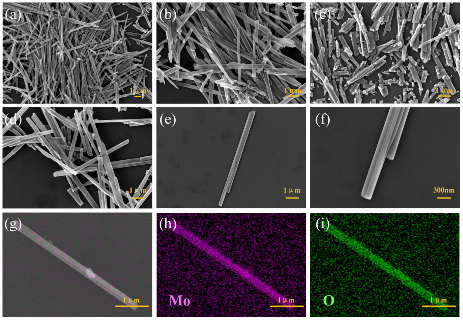
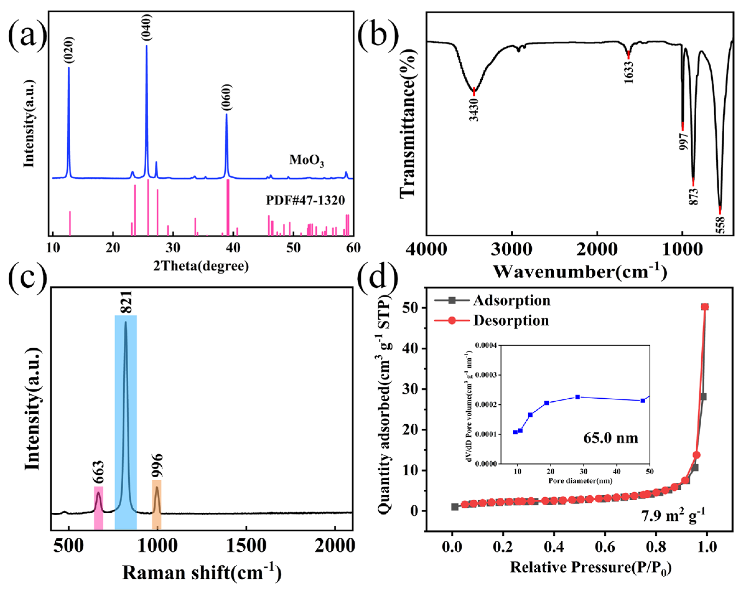
3.1. Structure and Morphology of Materials

Figure 2a–d are the SEM images of MoO3 prepared under hydrothermal conditions for 12 h, 18 h, 30 h, and 24 h, respectively. It can be observed that the overall morphology shows a nanorod shape. The MoO3 nanorods prepared under the hydrothermal condition of 12 h are relatively long in length as a whole. With the increase in the hydrothermal time, when the hydrothermal time becomes 30 h, the nanorods are fractured. This is attributed to the fact that with the increase in the hydrothermal time, under a high temperature and high pressure, defects occur in the crystal structure of the material, and distortion or deformation takes place, which limits the growth of the length and consequently causes the fracture of the nanorods. Figure 2d–f are SEM images of multiple and single MoO3 nanorods under the hydrothermal time of 24 h. Compared with other hydrothermal conditions, the length of the nanorods under this condition is relatively moderate. The nanorod-shaped materials with a moderate length can achieve a good balance among properties such as dispersibility, anisotropy, and carrier transport. Neither the problems of agglomeration and carrier transport obstruction due to excessive length, nor the loss of the advantage of anisotropy because of the overly short length, will occur. Figure 2g–i are elemental mapping images (EDS). The figures prove the existence and uniform distribution of Mo and O elements, indicating that the MoO3 material has been successfully synthesized.
To further explore the crystal structure of the prepared MoO3 materials, XRD tests were carried out on the materials. The results are shown in Figure 3a. Through comparison, it was found that the diffraction peaks of the samples were all consistent with the standard diffraction card JCPDF No. 47-1320, and no other impurity peaks appeared. This indicates that α-MoO3 was successfully prepared. Among them, the intensities of the diffraction peaks corresponding to the crystal planes (020), (040), and (060) were significantly higher than those of the diffraction peaks of other crystal planes, which indicates that the samples have good crystallinity. Figure 3b shows the FT-IR spectrum of MoO3. The peak at 997 cm−1 is caused by the stretching of the terminal oxygen of Mo = O. The peak at 873 cm−1 is attributed to the stretching of Mo-O-Mo. The peak at 558 cm−1 is due to the symmetric stretching of the O-Mo-O group. The characteristic peaks at 3430 cm−1 and 1633 cm−1 are caused by the stretching of the —OH group. The results indicate that the MoO3 material has been successfully synthesized [28]. Figure 3c presents the Raman spectrum of MoO3. It can be seen from the figure that three sharp Raman bands are displayed, located at 663 (B2g/B3g, vas, O—Mo—O stretch), 821 (Ag, vs, Mo = O stretching), and 996 cm−1 (Ag, vas, Mo = O stretching), respectively, all of which confirm the orthorhombic structure of α-MoO3 [29]. Figure 3d shows the BET and pore size distribution of the optimal MoO3 (180 °C/24 h/pH = 0.36). The curve inclines towards the Y-axis at the low-pressure (0–0.1) end, and there is an obvious adsorption hysteresis loop at the high-pressure (0.8–1) end, which belongs to a typical Type IV isotherm, indicating the existence of mesopores. The distribution of the corresponding pore size in the inset further demonstrates the presence of hierarchical micropores and mesopores.
Table 1 presents the comparison of BET for MoO3 prepared at different pH values. The specific surface area of the material prepared under the condition of pH = 0.36 is 7.9 m2 g−1, while the specific surface areas of the materials with pH = 0.58 and pH = 0.84 are 7.6 m2 g−1 and 7.5 m2 g−1, respectively. Since the increase in the BET surface area can provide more active sites and effective contact areas, it promotes the transfer and diffusion kinetics of the electrode surface and electrolyte components. According to the test, the BJH pore size under the condition of pH = 0.36 is larger (65 nm) than that for the other two conditions (48.7 nm, 40.0 nm).

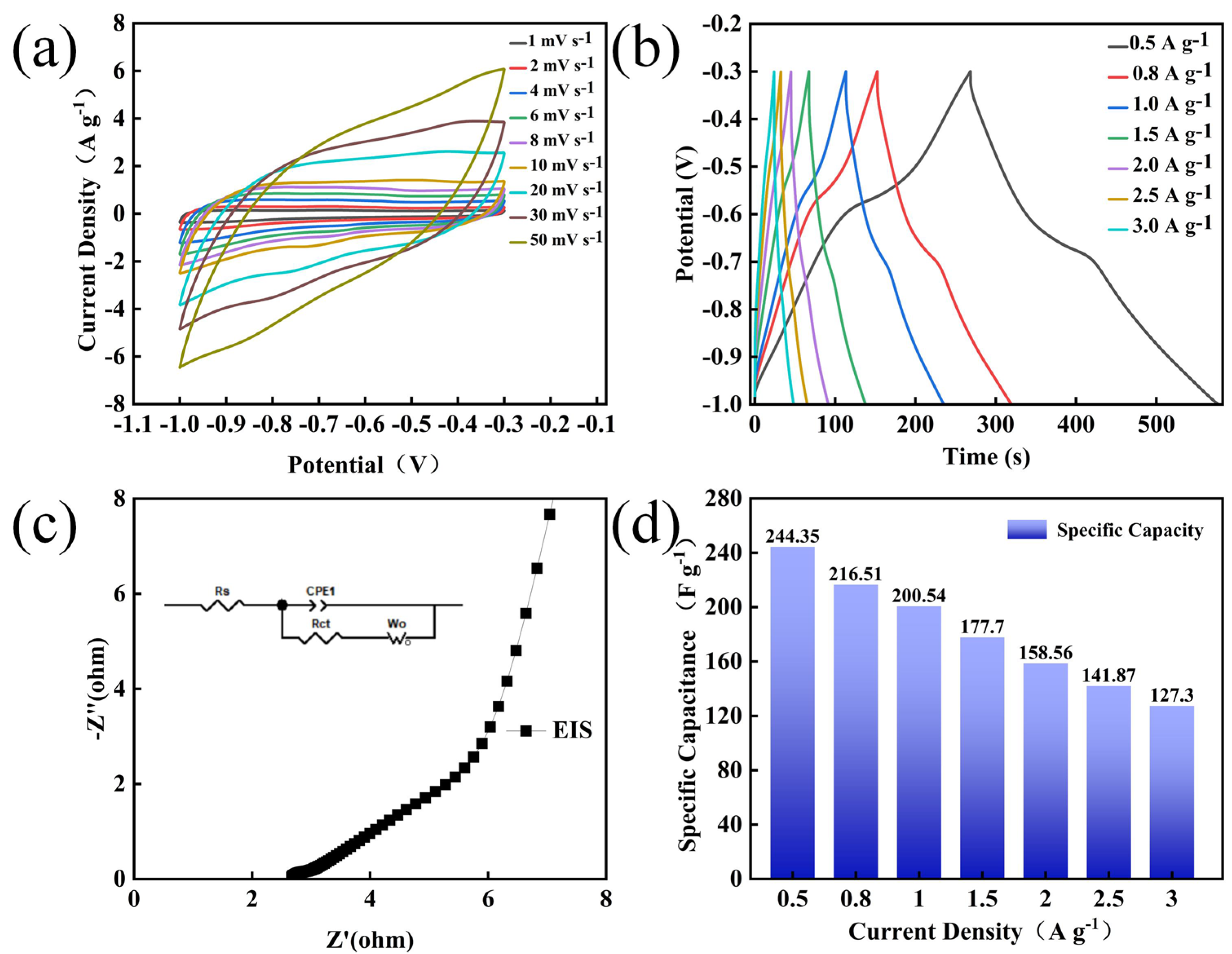
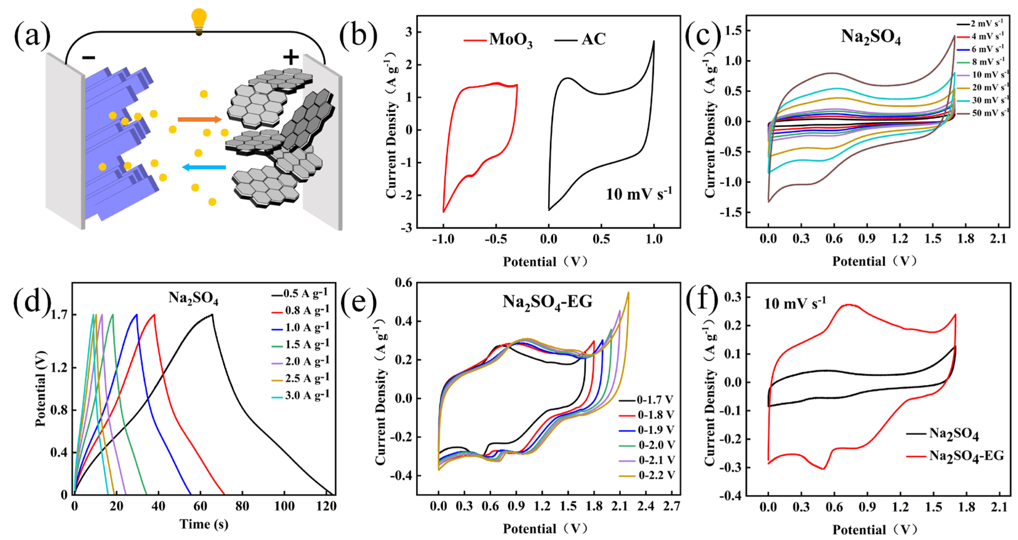
3.2. Electrochemical Performance

Figure 4 shows the electrochemical performance of the electrode materials prepared under different conditions using a three-electrode system. Figure 4a−c present the electrochemical results of the samples under different hydrothermal times: 12 h, 18 h, 24 h and 30 h. Figure 4a shows the comparison of CV curves at a scanning rate of 10 mV s−1. It can be observed that when the hydrothermal time is 24 h, the integral area of the CV curve is the largest, indicating that it has the largest specific capacitance. Figure 4b shows the comparison of GCD curves at a current density of 1 A g−1. Moreover, when the hydrothermal time is 24 h, the charge–discharge time is the longest. The charge–discharge curves all present approximately symmetrical triangular shapes, indicating that the electrode material has good reversibility [30]. The specific capacitance calculated from the GCD is shown in Figure 4c, and the specific capacities of 12 h, 18 h, 24 h, and 30 h are 47.28, 45.48, 200.54, and 57.21 F g−1 at a current density of 1 A g−1, respectively. The corresponding energy densities are 3.22, 3.10, 13.65, and 3.89 Wh kg−1, and the corresponding power densities are 448.98, 440.42, 402.39 and 443.56 W kg−1. Therefore, it can be concluded that the sample with a hydrothermal time of 24 h possesses the best performance, which is consistent with the results of CV and GCD.
Figure 4d−f show the electrochemical tests under different hydrothermal temperatures (160 °C, 180 °C, 200 °C). These imply that when the hydrothermal temperature is 180 °C, the area of the CV curve is the largest, the charge–discharge time is the longest, and the performance is the best. Moreover, according to the GCD calculations, the specific capacitances of the electrode materials prepared at 160 °C, 180 °C, and 200 °C at 1 A g−1 are 122.41 F g−1, 200.54 F g−1, and 110.27 F g−1 respectively. The test results consistently show that MoO3 prepared at a hydrothermal temperature of 180 °C exhibits the best electrochemical performance. This is attributed to the fact that an excessively high temperature directly damages the structure of the material, while a temperature that is too low fails to meet the formation conditions of MoO3 nanorods.
Figure 4g−i present the electrochemical tests carried out on the samples prepared under a hydrothermal time of 24 h and a hydrothermal temperature of 180 °C, with pH being the variable. Specifically, 2.6 mL, 1.7 mL, and 0.8 mL of concentrated nitric acid were, respectively, used to prepare the samples with pH values of 0.36, 0.58 and 0.84. It can be seen from the CV diagrams that when the pH is 0.84, the integral area of the CV curve is the largest, indicating that its specific capacitance is also the largest. It can be seen from Figure 4h that as the acidity increases, the charge–discharge time also increases accordingly, and the electrochemical performance of the samples is gradually improved. Through the above comparative analysis, it can be concluded that under a hydrothermal time of 24 h, a hydrothermal temperature of 180 °C, and a pH of 0.36, the prepared MoO3 achieves the optimal electrochemical performance.
To further evaluate the electrochemical performance of the prepared MoO3 nanomaterials, electrochemical tests were first carried out using a standard three-electrode system. Figure 5a shows the CV curves of the MoO3 nanocomposites at different scanning rates ranging from 1 to 50 mV s−1. It can be seen that with the increase in the scanning rate, all the curves exhibit similar shapes without obvious distortion, indicating that the CV curves at different scanning rates demonstrate good charge storage capabilities and efficient electrochemical responses at high rates [31]. Figure 5b presents the GCD curves with current densities ranging from 0.5 to 3 A g−1, and all the GCD curves display symmetrical charging and discharging processes without obvious plateaus, indicating good electrochemical reversibility. The EIS curve is shown in Figure 5c, where the inset is the simulated equivalent circuit diagram. In it, Rs and Rct are the series resistance and the constant phase element related to the double-layer capacitance and the Faraday resistance, respectively.
Figure 5d illustrates the comparative trend in the specific capacitance under different current densities. When the current density increases to five times the initial value, the specific capacitance retention rate is approximately 60%, demonstrating that the prepared electrode materials possess relatively good rate characteristics. The best performance was achieved under the experimental conditions of a hydrothermal time of 24 h, a hydrothermal temperature of 180 °C, and pH = 0.36. This is attributed to the nanorod-shaped MoO3, which allows the active sites to react more fully with ions, thereby improving the reaction rate and efficiency.
To further broaden the working voltage window of supercapacitors and improve their energy density, asymmetric supercapacitors were assembled using Na2SO4 and Na2SO4−EG as electrolytes, respectively; the charge storage mechanism of MoO3 can be calculated as follows [29]:
M o O 3 + N a + + e M o O 3 N a
M o O 3 s u r f a c e + N a + + e + M o O 3 N a + s u r f a c e
Insights into the charge storage process involved in the surface adsorption and intercalation of Na+ ions on MoO3 electrode materials can be obtained using Equations (5) and (6). The excellent electrochemical performances of the MoO3//AC supercapacitor are ascribed to the synergistic effect between exposing more electrochemically active sites of MoO3 materials and the higher decomposition voltage of the Na2SO4-EG electrolyte compared with the electrochemical stability window (1.23 V) for commonly aqueous electrolyte. The results are shown in Figure 6. Figure 6a shows the schematic diagram of the structure of the asymmetric supercapacitor. Figure 6b presents the CV curves of the MoO3 and AC electrodes at a scanning rate of 10 mV s−1, respectively, indicating that, theoretically, the stable voltage window of the asymmetric supercapacitor can be extended to 1.7 V. First, an asymmetric supercapacitor was assembled with MoO3 as the negative electrode, AC as the positive electrode, and Na2SO4 as the electrolyte. Figure 6c shows the CV curve of the MoO3//AC tested under the voltage window of 0–1.7 V for this asymmetric supercapacitor. It can be seen that with the assembly of the asymmetric device, the CV curve is in good shape and the voltage window has been successfully broadened to 1.7 V. Figure 6d shows the GCD results of the device under different current densities. All the curves exhibit linearity and relatively symmetrical triangular shapes, indicating that this supercapacitor has good electrochemical reversibility. Figure 6e shows the CV curves of the MoO3//AC tested under different voltage windows after adding a certain proportion of EG to the electrolyte. When the voltage window is 2.2 V, certain polarization occurs and small bubbles appear on the electrode plates, suggesting that the voltage window is too large at this time. Therefore, the voltage window is determined to be 2.1 V. It can be seen that adding a certain proportion of EG to the electrolyte has successfully broadened the voltage window from 0–1.7 V to 0–2.1 V, achieving the goal of widening the voltage. Figure 6f presents the CV curves of two electrolytes, Na2SO4−EG and Na2SO4, at a scanning rate of 10 mV s−1 under a voltage window of 0–1.7 V. It is evident that the CV area of Na2SO4−EG is larger, indicating that it has more abundant electroactive sites, higher electronic conductivity, and more accessible electrolyte ions, which leads to a higher specific capacitance.
Figure 7 shows the electrochemical performance tests of the MoO3//AC asymmetric supercapacitor assembled with the Na2SO4−EG electrolyte. Specifically, Figure 7a presents the CV curves at different scanning rates, demonstrating typical redox behaviors. Moreover, all the CV curves exhibit similar shapes. With the increase in the scanning rate, the positions of the oxidation peak and the reduction peak shift slightly towards the positive and negative potentials, respectively; this is mainly related to the polarization of the electrodes. Figure 7b shows the GCD curves of MoO3//AC. The approximately symmetrical GCD curves possess good coulombic efficiency and electrochemical reversibility, indicating that it has an excellent rate performance, ideal capacitive characteristics, and remarkable electrochemical reversibility [32]. The EIS test of the MoO3//AC device is shown in Figure 7c, where the inset is the simulated equivalent circuit diagram. The Rs and Rct values obtained through the fitting calculations are 2.6 Ω and 0.246 Ω, respectively. The above test results indicate that the MoO3//AC asymmetric device has relatively good capacitive characteristics. Figure 7d shows a Ragone plot comparing the electrochemical performance of supercapacitors with different electrodes. The supercapacitor can achieve an energy density of 8.28 Wh Kg−1 at a power density of 382.15 W Kg−1, which is superior to the previously reported hierarchical supercapacitor NiO ZnO//g−C3N4 (160 W Kg−1, 7.91 Wh Kg−1 [33]), microsphere ZnO−CoO//NC (5634.5 W Kg−1, 5.5 Wh Kg−1 [34]), MnO2//CNT(3300 W Kg−1, 7.2 Wh Kg−1 [35]), and Ni−Co oxide//AC (1902.9 W Kg−1, 7.4 Wh Kg−1 [36]). As shown in Figure 7e, the capacity retention rate of the MoO3//AC supercapacitor reached 109.2 % after being cycled 5,000 times at a current density of 2.0 A g−1. This is mainly due to the fact that the electrode material and the electrolyte ions make full contact during the cyclic charge–discharge process, thus improving the effective specific capacitance of the electrode. The prepared AC//MoO3 device can successfully light up the red LED lamp (Figure 7f) within a voltage window of 2.1 V, indicating that the MoO3 electrode material possesses excellent electrochemical properties and providing a new experimental basis for the preparation of supercapacitor electrode materials.
A table showing a comparison with previously published literature is provided in Table 2, showing that the aqueous MoO3//AC asymmetric supercapacitor assembled with the Na2SO4−EG electrolyte can retain more than 109.2% of its initial capacitance after 5000 cycles, because of the excellent mechanical stability and reduced volume expansion of MoO3 nanorods. Additionally, the MoO3//AC asymmetric supercapacitor displays the greatest working voltage (2.1 V), and this may be due to the strong coordination between EG molecules and Na+ ions; therefore, some H2O molecules are not in the Na+ solvation shell and do not participate in the decomposition process on the electrode surface, thus achieving a wide electrochemical window.

4. Conclusions

In this paper, the high aspect ratio of MoO3 nanorods provides more active sites for electrochemical reactions, and this unique morphology is achieved through a carefully optimized hydrothermal synthesis method (adjusting the hydrothermal temperature, hydrothermal time, and solution pH value) that precisely control the size and crystallinity of MoO3 nanorods. The advantages of high-performance MoO3 nanorods are their multivalence, numerous active sites, and high specific surface area, resulting in improved charge transfer reactions in the electrode/electrolyte and ion diffusion mobility. When the current density is 0.5 A g−1, the specific capacitance can reach 244.35 F g−1. Additionally, the assembled aqueous MoO3//AC asymmetric supercapacitor with Na2SO4−EG electrolyte can increase the working voltage from 1.7 V to 2.1 V, which is mainly attributable to the strong coordination between EG molecules and Na+ ions; therefore, some H2O molecules are not in the Na+ solvation shell and do not participate in the decomposition process on the electrode surface, thus achieving a wide electrochemical window (2.1 V). Meanwhile, a specific capacitance of 13.52 F g−1 can be achieved at a current density of 0.5 A g−1, an energy density of 8.28 Wh kg−1 and a power density of 382.15 W kg−1. The specific capacitance retention rate was 109.2 % after 5000 cycles, indicating that the prepared electrode materials possess a relatively high specific capacitance. In short, the assembled asymmetric supercapacitor successfully broadened the voltage window, and exhibited good electrochemical performance and cycling stability, providing new insights into regulating the wide voltage of supercapacitors from the perspective of electrolytes.

Author Contributions

Writing and Data curation, Z.L.; review and editing, X.M.; Validation, Y.S., K.Y. and R.Z.; Investigation, X.Y.; Supervision, M.L. All authors have read and agreed to the published version of the manuscript.

Funding

The work was supported by the National Natural Science Foundation of China (NSFC) (Grant Nos. 62004178), and Fundamental Research Program of Shanxi Province (Grant No. 202203021212149).

Data Availability Statement

Data available upon request.

Conflicts of Interest

The authors declare no conflicts of interest.

References

  1. Chen, J.L.; Xu, Z.F.; Zhu, H.L.; Liu, R.; Song, X.J.; Song, Q.; Wu, J.; Zhang, C.; Ding, L.; Dong, J.; et al. An ultrafast supercapacitor built by Co3O4 with tertiary hierarchical architecture. Vacuum 2020, 174, 8. [Google Scholar] [CrossRef]
  2. Guo, R.; Dang, L.Q.; Liu, Z.H.; Lei, Z.B. Incorporation of electroactive NiCo2S4 and Fe2O3 into graphene aerogel for high-energy asymmetric supercapacitor. Colloid. Surf. A Physicochem. Eng. Asp. 2020, 602, 9. [Google Scholar] [CrossRef]
  3. Libich, J.; Máca, J.; Vondrák, J.; Ech, O.; Sedlaíková, M. Supercapacitors: Properties and applications. J. Energy Storage 2018, 17, 224–227. [Google Scholar] [CrossRef]
  4. Zhang, M.; Yang, D.Y.; Li, J.T. Supercapacitor performances of MnO2 and MnO2/reduced graphene oxide prepared with various electrodeposition time. Vacuum 2020, 178, 9. [Google Scholar] [CrossRef]
  5. Mao, X.L.; Liu, H.; Xu, J.H.; Li, M.W.; Yang, W.Y. Surface reconstruction of Co3O4/rGO heterointerface enabling high-performance asymmetric supercapacitors. J. Energy Storage 2024, 102, 114128. [Google Scholar] [CrossRef]
  6. Pal, S.; Kumar Chattopadhyay, K. Fabrication of Molybdenum Trioxide Nanobelts as High Performance Supercapacitor. Mater. Today Proc. 2018, 5, 9776–9782. [Google Scholar] [CrossRef]
  7. Wang, L.C.; Gao, L.; Wang, J.; Shen, Y. MoO3 nanobelts for high-performance asymmetric supercapacitor. J. Mater. Sci. 2019, 54, 13685–13693. [Google Scholar] [CrossRef]
  8. Si, H.; Han, C.; Cui, Y.; Sang, S.; Liu, K.; Liu, H.; Wu, Q. The electrochemical properties of iodine cathode in a novel rechargeable hydrogen ion supercapattery system with molybdenum trioxide as anode. Electrochim. Acta 2021, 399, 139331. [Google Scholar] [CrossRef]
  9. Lahan, H.; Das, S.K. Reversible Al3+ ion insertion into tungsten trioxide (WO3) for aqueous aluminum-ion batteries. Dalton Trans. 2019, 48, 6337–6340. [Google Scholar] [CrossRef]
  10. Huang, S.; Li, Z.; Li, P.; Du, X.; Ma, M.; Liang, Z.; Su, Y.; Xiong, L. Ultrahigh-voltage aqueous electrolyte for wide-temperature supercapacitors. J. Mater. Chem. 2023, 11, 15532–15539. [Google Scholar] [CrossRef]
  11. D’Alessandro, A.; Bellani, S.; Gamberini, A.; Mastronardi, V.; Zappia, M.I.; Abruzzese, M.; Thorat, S.; Calcagno, E.; Bonaccorso, F. Water-based supercapacitors with amino acid electrolytes: A green perspective for capacitance enhancement. Batter. Supercaps 2024, 7, 7. [Google Scholar] [CrossRef]
  12. Wang, R.Y.; Shi, M.J.; Li, L.Y.; Zhao, Y.; Zhao, L.P.; Yan, C. In-situ investigation and application of cyano-substituted organic electrode for rechargeable aqueous Na-ion batteries. Chem. Eng. J. 2023, 451, 10. [Google Scholar] [CrossRef]
  13. Liu, S.Q.; Klukas, R.; Porada, T.; Furda, K.; Fernandez, A.M.; Balducci, A. Potassium formate-based electrolytes for high performance aqueous electrochemical capacitors. J. Power Sources 2022, 541, 6. [Google Scholar] [CrossRef]
  14. Nandagudi, A.; Nagarajarao, S.H.; Santosh, M.S.; Basavaraja, B.M.; Malode, S.J.; Mascarenhas, R.J.; Shetti, N.P. Hydrothermal synthesis of transition metal oxides, transition metal oxide/carbonaceous material nanocomposites for supercapacitor applications. Mater. Today Sustain. 2022, 19, 19. [Google Scholar] [CrossRef]
  15. Duan, H.; Zhao, Z.; Lu, J.; Hu, W.; Pang, H. When Conductive MOFs Meet MnO2: High Electrochemical Energy Storage Performance in an Aqueous Asymmetric Supercapacitor. ACS Appl. Mater. Intefaces 2021, 13, 33083–33090. [Google Scholar] [CrossRef]
  16. Wang, T.Y.; Liu, J.; Ma, Y.X.; Han, S.; Gu, C.D.; Lian, J.S. P-N heterojunction NiO/ZnO electrode with high electrochemical performance for supercapacitor applications. Electrochim. Acta 2021, 392, 11. [Google Scholar] [CrossRef]
  17. Cheng, S.T.; Zhang, Y.X.; Liu, Y.P.; Sun, Z.H.; Cui, P.; Zhang, J.L.; Hua, X.; Su, Q.; Fu, J.; Xie, E. Energizing Fe2O3-based supercapacitors with tunable surface pseudocapacitance via physical spatial-confining strategy. Chem. Eng. J. 2021, 406, 11. [Google Scholar] [CrossRef]
  18. Sun, L.; Liu, Y.; Yan, M.; Yang, Q.J.; Liu, X.Y.; Shi, W.D. Lewis acid etched NixCo1-xSe2 derived from ZIF-L on CoO nanowires for hybrid-supercapacitors. Chem. Eng. J. 2022, 431, 14. [Google Scholar] [CrossRef]
  19. De Castro, I.A.; Datta, R.S.; Ou, J.Z.; Castellanos-Gomez, A.; Sriram, S.; Daeneke, T.; Kalantar-zadeh, K. Molybdenumoxides-from fundamentals to functionality. Adv. Mater. 2017, 29, 1701619. [Google Scholar] [CrossRef]
  20. Hu, X.L.; Zhang, W.; Liu, X.X.; Mei, Y.N.; Huang, Y. Nanostructured Mo-based electrode materials for electrochemical energy storage. Chem. Soc. Rev. 2015, 44, 2376–2404. [Google Scholar] [CrossRef]
  21. Liu, H.; Liu, X.; Wang, S.L.; Liu, H.K.; Li, L. Transition metal based battery-type electrodes in hybrid supercapacitors: A review. ESM 2020, 28, 122–145. [Google Scholar] [CrossRef]
  22. Pan, Z.H.; Yang, C.H.; Li, Y.; Hu, X.; Ji, X.H. Rational design of A-CNTs/KxMnO2 and Ti3C2Tx/MoO3 free-standing hybrid films for flexible asymmetric supercapacitor. Chem. Eng. J. 2022, 428, 131138. [Google Scholar] [CrossRef]
  23. Huang, Z.Y.; Zhang, Z.; Qi, X.; Ren, X.H.; Xu, G.H.; Wan, P.B.; Sun, X.M.; Zhang, H. Wall-like hierarchical metal oxide nanosheet arrays grown on carbon cloth for excellent supercapacitor electrodes. Nanoscale 2016, 8, 13273–13279. [Google Scholar] [CrossRef]
  24. Zhang, S.W.; Yin, B.S.; Liu, C.; Wang, Z.B.; Gu, D.M. Self-assembling hierarchical NiCo2O4/MnO2 nanosheets and MoO3/PPy core-shell heterostructured nanobelts for supercapacitor. Chem. Eng. J. 2017, 312, 296–305. [Google Scholar] [CrossRef]
  25. Noby, S.Z.; Mohanty, A.; Zirak, P.; Ramadoss, A.; Schmidt-Mende, L. Ramadoss, Hierarchical carbon coated vertically aligned α-MoO3 nanoblades anode materials for supercapacitor application. J. Alloys Compd. 2022, 918, 165530. [Google Scholar] [CrossRef]
  26. Yu, C.Y.; Xu, H.; Gong, Y.J.; Chen, R.Y.; Hui, Z.Y.; Zhao, X.; Sun, Y.; Chen, Q.; Zhou, J.; Ji, W.; et al. The Jahn-Teller Effect for Amorphization of Molybdenum Trioxide towards High-Performance Fiber Supercapacitor. Research 2021, 2021, 11. [Google Scholar] [CrossRef]
  27. Mao, X.L.; He, X.; Yang, W.Y.; Liu, H.; Zhou, Y.J.; Xu, J.H.; Yang, Y. Hierarchical holey Co9S8@S-rGO hybrid electrodes for high-performance asymmetric supercapacitors. Electrochim. Acta 2019, 328, 11. [Google Scholar] [CrossRef]
  28. Hu, H.M.; Deng, C.H.; Xu, J.C.; Zhang, K.H.; Sun, M. Metastable h-MoO3 and stable α-MoO3 microstructures: Controllable synthesis, growth mechanism and their enhanced photocatalytic activity. J. Exp. Nanosci. 2015, 10, 1336–1346. [Google Scholar] [CrossRef]
  29. Yang, J.; Xiao, X.; Chen, P.; Zhu, K.; Cheng, K.; Ye, K.; Wang, G.; Cao, D.; Yan, J. Creating oxygen-vacancies in MoO3-x nanobelts toward high volumetric energy-density asymmetric supercapacitors with long lifespan. Nano Energy 2019, 58, 455–465. [Google Scholar] [CrossRef]
  30. Xu, L.M.; Zhou, W.Q.; Chao, S.X.; Liang, Y.M.; Zhao, X.Q.; Liu, C.C.; Xu, J. Advanced Oxygen-Vacancy Ce-Doped MoO3 Ultrathin Nanoflakes Anode Materials Used as Asymmetric Supercapacitors with Ultrahigh Energy Density. Adv. Energy Mater. 2022, 12, 13. [Google Scholar] [CrossRef]
  31. Saraf, M.; Shuck, C.E.; Norouzi, N.; Matthews, K.; Inman, A.; Zhang, T.; Pomerantseva, E.; Gogotsi, Y. Free-Standing α-MoO3/Ti3C2 MXene Hybrid Electrode in Water-in-Salt Electrolytes. Energy Environ. Mater. 2023, 6, 6–14. [Google Scholar] [CrossRef]
  32. Mao, X.; Xu, J.; He, X.; Yang, W.; Yang, Y.; Xu, L.; Zhao, Y.; Zhou, Y. All-solid-state flexible microsupercapacitors based on reduced graphene oxide/multi-walled carbon nanotube composite electrodes. Applied Surface Science. Appl. Surf. Sci. 2018, 435, 1228–1236. [Google Scholar] [CrossRef]
  33. Chen, X.; Wang, X.; Liu, F.; Song, X.; Cui, H. Fabrication of NiO–ZnO-modified g C3N4 hierarchical composites for high-performance supercapacitors. Vacuum 2020, 178, 109453. [Google Scholar] [CrossRef]
  34. Yao, D.; Wang, F.L.; Lei, W.; Hua, Y.; Xia, X.F.; Liu, J.P.; Hao, Q. Oxygen vacancies boosting ultra-stability of mesoporous ZnO-CoO@N-doped carbon microspheres for asymmetric supercapacitors. Sci. China-Mater. 2020, 63, 2013–2027. [Google Scholar] [CrossRef]
  35. Ko, W.Y.; Chen, Y.F.; Lu, K.M.; Lin, K.J. Porous honeycomb structures formed from interconnected MnO2 sheets on CNT-coated substrates for flexible all-solid-state supercapacitors. Sci. Rep. 2016, 6, 18887. [Google Scholar] [CrossRef]
  36. Tang, C.; Tang, Z.; Gong, H. Hierarchically Porous Ni-Co Oxide for High Reversibility Asymmetric Full-Cell Supercapacitors. J. Electrochem. Soc. 2012, 159, A651. [Google Scholar] [CrossRef]
  37. Yan, L.; Huang, J.H.; Guo, Z.W.; Dong, X.L.; Wang, Z.; Wang, Y.G. Solid-State Proton Battery Operated at Ultralow Temperature. ACS Energy Lett. 2020, 5, 685–691. [Google Scholar] [CrossRef]
  38. Xu, T.Z.; Xu, Z.M.; Yao, T.Y.; Zhang, M.; Chen, D.; Zhang, X.; Shen, L. Discovery offast and stableproton storage in bulk hexagonal molybdenum oxide. Nat. Commun. 2023, 14, 8360. [Google Scholar] [CrossRef]
  39. Zhu, Y.L.; Tan, Y.T.; Li, H. MoO3 nanoplates preparation via self-sacrifice C3N4 for supercapacitors in an acid electrolyte. J. Energy Storage 2023, 60, 106657. [Google Scholar] [CrossRef]
  40. Iamprasertkun, P.; Hirunpinyopas, W.; Tripathi, A.M.; Bissett, M.A.; Dryfe, R.A.W. Electrochemical intercalation of MoO3-MoS2 composite electrodes: Charge storage mechanism of non-hydrated cations. Electrochim. Acta 2019, 307, 176–187. [Google Scholar] [CrossRef]
Figure 1. Schematic diagram of preparation of MoO3.
Nanomaterials 14 02029 g001
Figure 2. (ac) SEM images of MoO3 at hydrothermal times of 12 h, 18 h, 30 h; (df) SEM image of MoO3 under hydrothermal time of 24 h; (gi) EDS spectra of different element distributions in MoO3.
Nanomaterials 14 02029 g002
Figure 3. (a) XRD pattern of MoO3 material; (b) FT−IR spectrum of MoO3 material; (c) Raman spectrum of MoO3; (d) adsorption–desorption curves and pore size distribution diagrams.
Nanomaterials 14 02029 g003
Figure 4. Comparison of electrochemical testing performance of MoO3 under different conditions: (ac) comparison charts of CV (10 mV s−1), GCD (1 A g−1), and specific capacity (1 A g−1) under varying hydrothermal times; (df) comparison charts of CV (10 mV s−1), GCD (1 A g−1), and specific capacity (1 A g−1) at different hydrothermal temperatures; (gi) comparison charts of CV (10 mV s−1), GCD (1 A g−1), and specific capacity (1 A g−1) under varying acidity indices.
Nanomaterials 14 02029 g004
Figure 5. Electrochemical performance charts of MoO3 under hydrothermal conditions with a duration of 24 h, pH = 0.36, and at 180 °C: (a) CV diagram; (b) GCD diagram; (c) EIS diagram; (d) specific capacity diagram at 1 Ag−1.
Nanomaterials 14 02029 g005
Figure 6. Electrochemical performance of MoO3//AC supercapacitors: (a) schematic diagram of the MoO3//AC supercapacitor electrolytic cell; (b) comparison chart of AC and MoO3 CV at 10 mV s−1; (c) Na2SO4 as electrolyte: CV plot at 0−1.7 V; (d) Na2SO4 as electrolyte: GCD plot at 0−1.7 V; (e) Na2SO4 −EG as electrolyte: CV plots at different voltage windows of 10 mV s−1; (f) comparison of CVs of Na2SO4 and Na2SO4 −EG at 10 mV/s within a voltage window of 0−1.7 V;.
Nanomaterials 14 02029 g006
Figure 7. Electrochemical performance of MoO3//AC supercapacitors: (a) CV plot at 0−2.1 V; (b) GCD diagram at 0−2.1 V; (c) EIS diagram at 0−2.1 V; (d) Ragone plot (energy densities vs. power density); (e) cycle life diagram of supercapacitors (current density of 2 A g−1); (f) schematic diagram of supercapacitor device illuminating LED light.
Nanomaterials 14 02029 g007
Table 1. Comparison of BET of MoO3 prepared at different pH values.
SamplesPH = 0.36PH = 0.58PH = 0.84
BET surface area
(m2 g−1)
7.97.67.5
BJH average pore size (nm)65.048.740.0
Table 2. Performance comparison table of supercapacitors.
SystemVoltage WindowNumber of CyclesCapacitance
Retention Rate (%)
Ref.
MnO2 @GF//MoO30.85–1.55 V30081%[37]
I2-NP-CP@Nafion//MoO30–1.8 V50093.2%[8]
Cu0.82Co0.18HCF//h-MoO30–1.6 V10,00083%[38]
YP50//MoO30–1.4 V150084%[39]
Graphene composite//MoO3−MoS2−0.8–0 V50050.3%[40]
AC//MoO30–2.1 V50001092%This work
Disclaimer/Publisher’s Note: The statements, opinions and data contained in all publications are solely those of the individual author(s) and contributor(s) and not of MDPI and/or the editor(s). MDPI and/or the editor(s) disclaim responsibility for any injury to people or property resulting from any ideas, methods, instructions or products referred to in the content.

