Article

Preparation of Remote Plasma Atomic Layer-Deposited HfO2 Thin Films with High Charge Trapping Densities and Their Application in Nonvolatile Memory Devices

1
Department of Advanced Materials Engineering, Tech University of Korea, Siheung 15073, Republic of Korea
2
EN2CORE Technology Inc., Daejeon 18469, Republic of Korea
3
Korea Evaluation Institute of Industrial Technology, Seoul 06152, Republic of Korea
*
Author to whom correspondence should be addressed.
Nanomaterials 2023, 13(11), 1785; https://doi.org/10.3390/nano13111785
Submission received: 29 April 2023 / Revised: 25 May 2023 / Accepted: 30 May 2023 / Published: 1 June 2023
(This article belongs to the Special Issue Ferroelectric Nanostructures and Thin Films)

Abstract

:
Optimization of equipment structure and process conditions is essential to obtain thin films with the required properties, such as film thickness, trapped charge density, leakage current, and memory characteristics, that ensure reliability of the corresponding device. In this study, we fabricated metal–insulator–semiconductor (MIS) structure capacitors using HfO2 thin films separately deposited by remote plasma (RP) atomic layer deposition (ALD) and direct-plasma (DP) ALD and determined the optimal process temperature by measuring the leakage current and breakdown strength as functions of process temperature. Additionally, we analyzed the effects of the plasma application method on the charge trapping properties of HfO2 thin films and properties of the interface between Si and HfO2. Subsequently, we synthesized charge-trapping memory (CTM) devices utilizing the deposited thin films as charge-trapping layers (CTLs) and evaluated their memory properties. The results indicated excellent memory window characteristics of the RP-HfO2 MIS capacitors compared to those of the DP-HfO2 MIS capacitors. Moreover, the memory characteristics of the RP-HfO2 CTM devices were outstanding as compared to those of the DP-HfO2 CTM devices. In conclusion, the methodology proposed herein can be useful for future implementations of multiple levels of charge-storage nonvolatile memories or synaptic devices that require many states.

1. Introduction

Scaling of the silicon nitride-based charge-trapping layers (CTLs) used in NAND flash memory devices is challenging due to the recent ultra nano-sized processing and high integration of semiconductor devices [1,2,3,4]. With a decrease in the required film thickness, the trapped charge density (Nt) of the CTL decreases, reducing the memory window (∆VFB) margin that can distinguish the device on/off states at the same operating voltage and program/erase (P/E) time. Additionally, the increase in leakage current owing to the decrease in film thickness degrades the memory retention characteristics, thereby leading to problems in terms of device reliability. To address these issues, researchers have been actively applying high-k materials, such as HfO2, Al2O3, TiOx, ZnO, and ZrO2, to CTLs [5,6,7,8,9,10]. High-k-based oxides exhibit advantages, including small equivalent oxide thicknesses (EOTs), large band offsets to Si, and high Nt values, over conventional silicon nitride. Moreover, the films of these oxides are expected to achieve the memory characteristics needed for device operation even at a thickness of a few nanometers [11]. Charge trapping properties of high-k-based oxides have been improved by various methods such as noble metal doping [11,12,13], nanocrystallization [14,15,16,17], and high-temperature heat treatment [18,19]; however, these methods have the disadvantage of difficult application to actual mass productions. Furthermore, thin films with charge trapping properties have been achieved by changing the deposition method. Recent studies have reported variations in the charge trapping properties of HfO2 thin films with respect to the atomic layer deposition (ALD) temperature and reactant activation [8,20].
ALD is currently the dominant process for depositing thin films with thicknesses of several nanometers. Based on the energy transfer method used for the activation of the reactive gas, ALD is divided into thermal and plasma-enhanced (PE) ALD. Among them, PEALD is mainly used at present due to its lower process temperature, higher film density, faster deposition rate, and shorter one-cycle time [21]. PEALD is classified into direct-plasma (DP) and remote plasma (RP) ALD. However, in the case of DPALD, where the plasma is discharged in the process chamber to deliver energy to the reactive gas, ions in the plasma can bombard the substrate or film surface, causing interfacial damage and degrading film properties [22,23,24]. RPALD, in which the plasma discharge area is separated from the process chamber and only activated radicals are injected into the process chamber, can solve this plasma damage problem. Nevertheless, the lifetimes of plasma-activated radicals are not long; thus, optimization of equipment structure and process conditions is essential to obtain thin films with the required properties [25,26].
In this study, we fabricated metal–insulator–semiconductor (MIS) structure capacitors using HfO2 thin films separately deposited by RPALD and DPALD and determined the optimal process temperature by measuring the leakage current and breakdown strength as functions of process temperature. Furthermore, the ∆VFB characteristics of each capacitor were investigated using capacitance–voltage (C–V) measurements. The effects of the plasma application method on the charge trapping performances of the HfO2 thin films and properties of the interface between Si and HfO2 were analyzed via electrical analyses. Additionally, the formation of an interfacial layer between Si and HfO2 thin films was verified by cross-sectional observation of the device. Finally, we synthesized charge-trapping memory (CTM) devices using the developed interfacial layer as a tunneling oxide (TO), RP- or DP-HfO2 thin films as CTLs, and DP-Al2O3 thin film as a blocking oxide (BO). Then, we examined the applicability of the devices to actual memory devices via electrical measurements of the corresponding properties such as ∆VFB, P/E speed, memory retention time, and cycling endurance.

2. Materials and Methods

2.1. Fabrication of Devices

A four-inch p-type (100) Si wafer with a specific resistivity of 1–30 Ω∙cm was washed by SC-1 cleaning and then immersed in buffered oxide etchant for approximately 30 s to remove the native oxide on the Si wafer. HfO2 and Al2O3 thin films were deposited on the resulting wafer using a PEALD system (iOV-dx2, iSAC Research, Daejeon, Republic of Korea). DP was generated by a built-in plasma generator in the PEALD equipment. RP was produced by an RP system (En2ra-RPS, EN2CORE Technology, Daejeon, Republic of Korea) in a separate room from the primary chamber, and the radicals were transferred to the main chamber via a shower head based on pressure difference. Tetrakis(ethylmethylamino)-hafnium (TEMAH, iChems, Hwaseong, Republic of Korea) and trimethylaluminum (TMA, iChems, Hwaseong, Republic of Korea) were employed as precursors for HfO2 and Al2O3 thin-film deposition, respectively, and O2 was used as the reactive gas. Subsequently, Pt electrodes with diameters of 200 μm and thicknesses of 50 nm were formed by the lift-off method. Pt deposition was conducted for 3 min at room temperature using a direct current magnetron sputter. Finally, post metallization annealing was performed for 20 min under a N2 atmosphere at 400 °C using rapid thermal annealing equipment.

2.2. Evaluation of Device Characteristics

Thicknesses of the deposited HfO2 and Al2O3 films were measured using an ellipsometer (Elli-SE, Ellipso Technology, Suwon, Republic of Korea). Cross-sectional morphologies and crystallinities of the films were investigated via field-emission transmission electron microscopy (TEM) (FE-TEM, Tecnai G2 F20, FEI, Hillsboro, OR, USA). Furthermore, compositions and chemical bonding states of the HfO2 films were analyzed by X-ray photoelectron spectroscopy (XPS, AXIS-NOVA, Manchester, UK). Electrical characteristics, such as current–voltage (I–V) characteristics, ∆VFB, and P/E speed, of the device were evaluated using a semiconductor characterization system (4200A-SCS, Keithley, Cleveland, OH, USA) connected to a micro probe station (APX-6B, WIT Co., Suwon, Republic of Korea).

3. Results and Discussion

Under the optimized process conditions reported in our previous studies [27,28], MIS capacitors were fabricated by depositing DP- and RP-HfO2 thin films on p-Si wafers and developing Pt electrodes. HfO2 thin films were deposited by splitting the temperature in the range of 200–260 °C, which was considered the process window, and the thickness of the deposited film was determined to be approximately 10 nm by the ellipsometer. Figure 1 shows the results of the I–V measurements conducted to measure the leakage currents and breakdown strength characteristics of the MIS capacitors based on DP- and RP-HfO2 thin films. The current was calculated with an increase in the negative bias. The leakage current and breakdown strength of the DP-HfO2 MIS capacitor slightly varied with an increase in the process temperature (Figure 1a). This suggested that the ions bombarded on the thin film by DP further participated in the reaction of the precursor with the reactive gas, mitigating the impact of process temperature on the leakage current and breakdown strength. In contrast, the leakage current and breakdown voltage characteristics of the RP-HfO2 MIS capacitor changed with an increase in the process temperature (Figure 1b). The leakage current was lowest, and the breakdown voltage characteristics were highest at 220 °C. This was expected to be owing to the strong influence of thermal energy on the reaction of the radicals activated by RP with the sources adsorbed on the film during film formation. Therefore, determining the optimum process temperature for RPALD of thin films by electrical characterization, for example, I–V measurement, is necessary. The breakdown field of the HfO2 MIS capacitor based on the DP-HfO2 film (DP-HfO2 MIS capacitor) deposited at 220 °C was approximately 3 MV/cm lower than that of the capacitor based on the RP-HfO2 film deposited at 220 °C (RP-HfO2 MIS capacitor). In the DP method, deposition and plasma discharge occur in the same space, which can damage the substrate and thin film via ion bombardment [22,23,24]. In the current DP process, HfO2 thin films were deposited on the Si wafer surface, which was subjected to ion bombardment. Consequently, the formation of unstable interfacial layers and defects within the films was anticipated, leading to a reduction in the breakdown fields of the corresponding capacitors.
Prior to the analysis of the interfacial damage and internal defects in thin films, capacitance–voltage (C–V) measurements of DP- and RP-HfO2 MIS capacitors were performed in a forward–backward dual sweeping fashion at room temperature and 1 MHz. C–V curves of both DP- and RP-HfO2 MIS capacitors demonstrated counterclockwise hystereses (Figure 2a,b, respectively). Counterclockwise hysteresis is a typical hysteresis loop caused by charge trapping. When an electron is trapped at a charge trapping site in an oxide film under a positive bias, the flat band voltage (VFB) shifts in the positive direction, which is called the program state. However, when a hole is trapped under a negative bias and an electron is detrapped, VFB shifts in the negative direction, which is called the erase state. ∆VFB is defined as the difference between the VFB values in the program and erase states and increases with an increase in the sweeping voltage. For the DP-HfO2 MIS capacitor, ∆VFB slightly increased with an increase in the sweeping voltage. In contrast, for the RP-HfO2 MIS capacitor, ∆VFB significantly increased with an increase in the sweeping voltage, reaching 2.22 V at a sweeping voltage of ±5 V. This indicated excellent charge trapping efficiency and high potential of the RP-HfO2 thin film for application as a CTL [7,29]. For the application of oxide thin films as CTLs, the Nt in these films must be high. Nt values per unit areas of DP- and RP-HfO2 thin films can be calculated at the point where the ∆VFB is saturated with an increase in the sweeping voltage using the following equation [18,30]:
N t = C o x V F B q A
where Cox is the capacitance in the accumulation region, q is the charge of the electron, and A is the effective area of the Pt top electrode. Using Equation (1), we calculated the Nt values of the DP- and RP-HfO2 thin films at the sweeping voltage of ±5 V; the Nt values were 4.48 × 10¹² and 1.25 × 1013 cm−2, respectively. The Nt of the RP-HfO2 thin film were more than twice that of the DP-HfO2 thin film. However, these values were evaluated before the saturation of the ∆VFB values of the capacitors by the sweeping voltage. The maximum Nt for each film could not be calculated because the film broke down before the saturation of ∆VFB. The center of hysteresis for the DP-HfO2 film is shifted towards negative voltage, whereas the center of hysteresis for the RP film is shifted towards positive voltage. This opposing shift can be attributed to their distinct distributions of oxide traps, which will be elaborated upon in the results of constant current stress measurements as below.
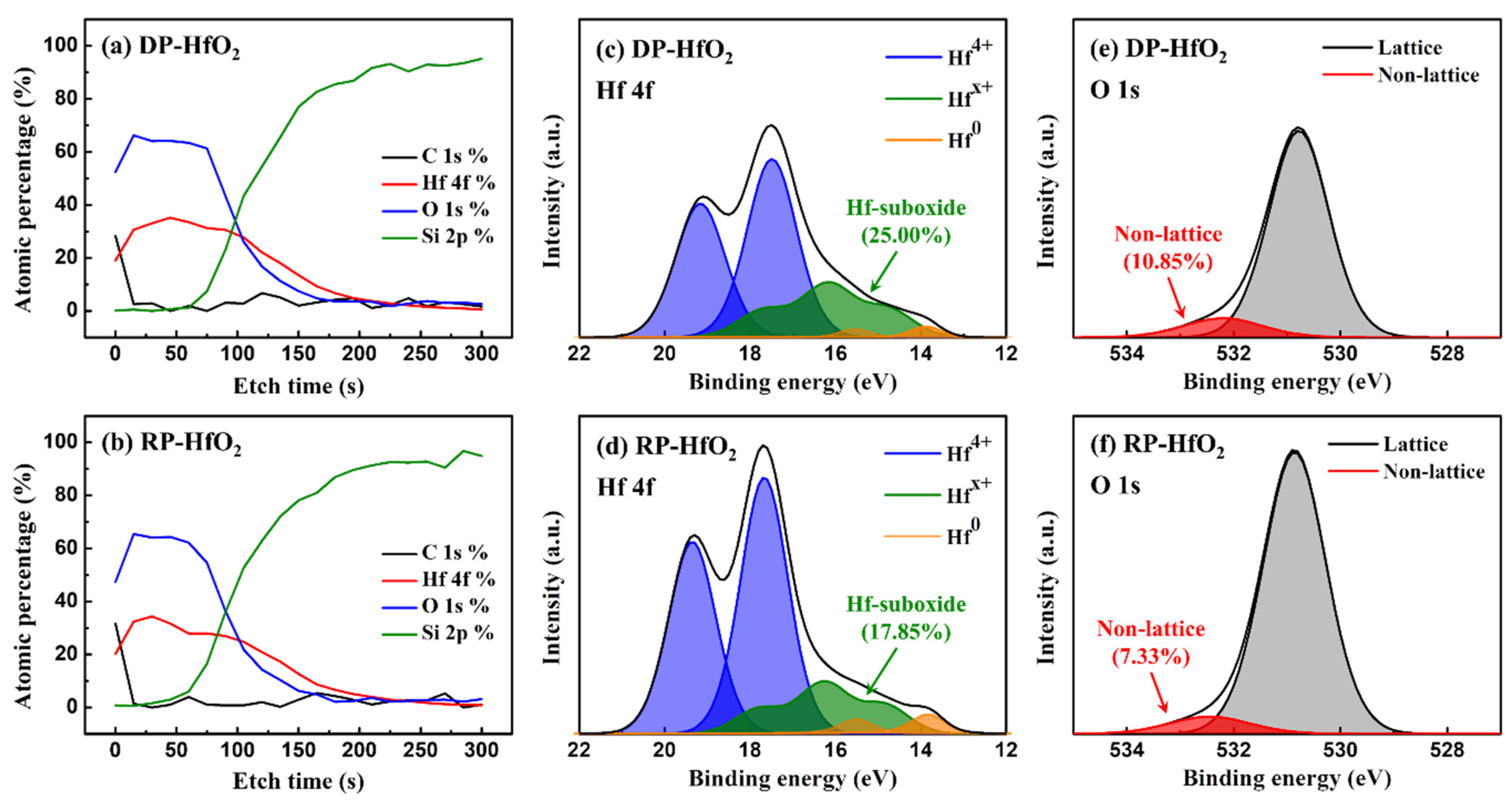
Charges are trapped in high-k oxide thin films by the intrinsic defects, such as O vacancies and interstitial O atoms, in the films [31]. Therefore, we indirectly compared the Nt values of the DP- and RP-HfO2 thin films by measuring the ratio of the number of lattice bonds to the number of non-lattice bonds in the film via XPS. XPS depth profiling demonstrated that the C 1s atomic percentages in both DP- and RP-HfO2 thin films were negligible, except for those on the surfaces (Figure 3a,b, respectively). The presence of C in the thin films is attributed to the incomplete reaction of the reactive gas with the precursor containing C. Thus, both films were deposited under optimal process conditions. Hf 4f and O 1s narrow scans were conducted on the bulk portion of each thin film. Each peak was analyzed using CasaXPS (Version 2.3.25PR1.0). At first, the Shirley-type background was removed from all spectra, and the peaks were fitted using a Gaussian–Lorentzian function. For the deconvolution of the Hf 4f peaks in Figure 3c,d, the ratio of Hf 4f5/2 peaks to Hf 4f7/2 peaks was fixed at 3:4 [32]. In this case, the spin-orbit splitting was 1.66 eV. We also discovered that the sub-oxide Hfx+ peak was represented by the sum of two doublets, and the metallic Hf0 peak was in agreement with the data reported in the literature, that is, it appeared at a distance of approximately 3.4–4.1 eV from the Hf4+ doublet [33,34]. After peak deconvolution, the percentages of non-stoichiometric HfO2−x in DP- and RP-HfO2 thin films were 25.00 and 17.85%, respectively. The O 1s peak can be deconvolved into a lattice peak owing to O bonding in the full crystal and a non-lattice peak due to bonding of O vacancies, O-H, and C-O (Figure 3e,f). In this case, the non-lattice peak emerges at a distance of approximately 1.4–1.6 eV from the lattice oxide peak [35]. The percentages of the non-lattice peaks for DP- and RP-HfO2 thin films were evaluated to be 10.85 and 7.33%, respectively. Higher amounts of non-stoichiometric hafnia and non-lattice oxygen can indicate more intrinsic defects. According to the results of Hf 4f and O 1s XPS, we can infer that the number of intrinsic defects in the DP-HfO2 thin film is higher than that in the RP-HfO2 thin film. This is also consistent with the tendencies of lower breakdown voltages for DP-HfO2 thin films (Figure 1). Nevertheless, this result does not explain why the RP-HfO2 thin film, which has fewer defects that can act as charge-trapping sites, exhibits better ∆VFB characteristics than those of the DP-HfO2 thin film.
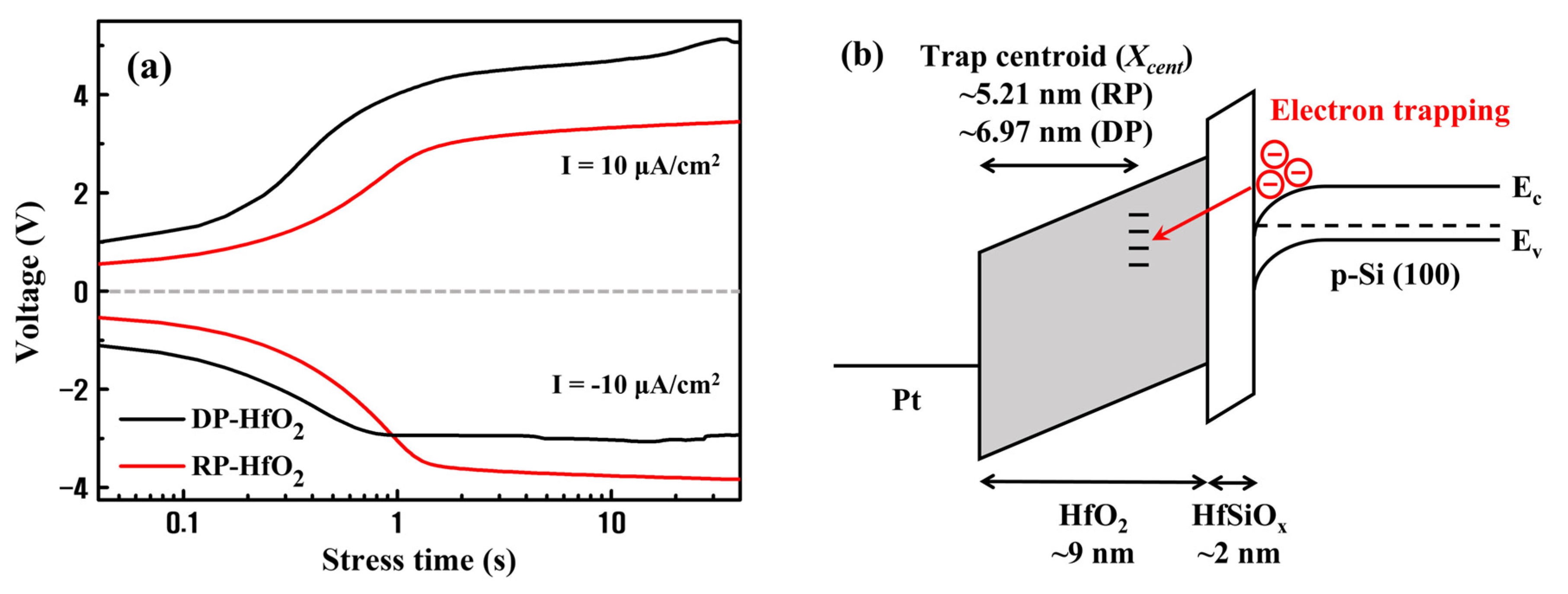
To determine the reason for the outstanding charge trapping properties of RP-HfO2 thin films, constant current stress (CCS) measurements were performed. CCS analysis is a widely applied method to estimate the charge trap centroid (Xcent) of bilayer gate stacks [29,36,37]. These measurements allowed us to identify the majority trap sites in the HfO2 thin film. The capacitor was exposed to a constant current density of ±10 μA/cm2, and the shift in voltage was measured in the I-V characteristic as the stress time increased. The voltage shift was caused by the trapping of charges in the oxide layer. Xcent of the capacitor was evaluated via the CCS measurement using the following equation:
X c e n t = t s t a c k [ 1 ( V g / V g + ) ]
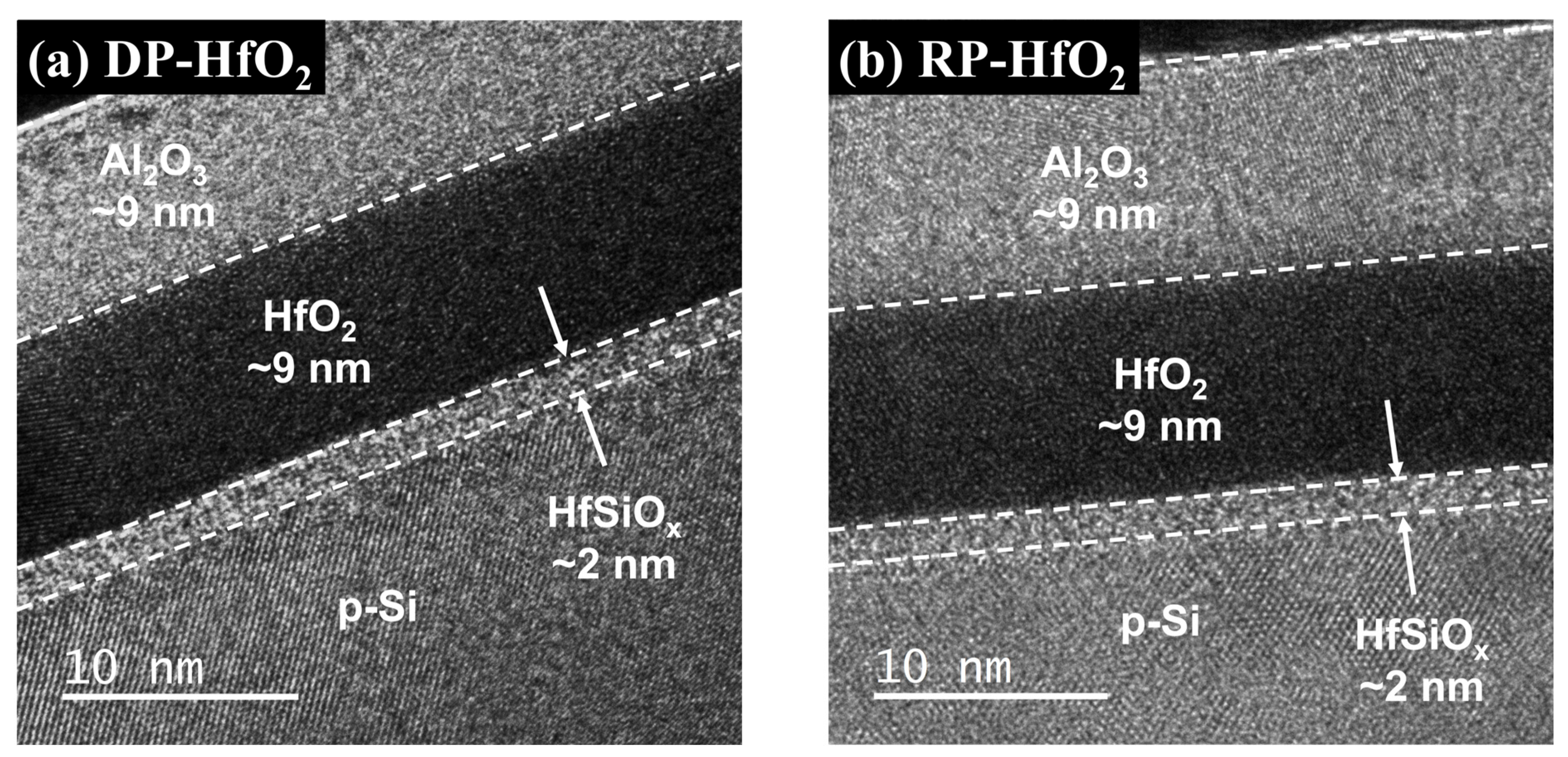
where Xcent is the distance from the gate electrode, tstack is the thickness of the oxide layer, and ∆Vg+ and ∆Vg are the positive and negative voltage shifts after the application of a CCS, respectively. TEM images of the cross-sections of DP- and RP-HfO2 MIS capacitors indicated that the thickness of the deposited HfO2 film was approximately 9 nm and an interfacial layer with a thickness of approximately 2 nm formed by an interfacial reaction existed between HfO2 and Si. Previous studies have demonstrated that the interfacial layers generated during the deposition of HfO2 thin films on Si wafers by DP and RPALD were Hf- and Si-rich Hf-silicates, respectively. This difference between the compositions of DP- and RP-HfO2 thin films is because of the interaction between Hf and SiO2−x induced by energetic reactants in the plasma states [38,39]. Assuming that the dielectric constant of the deposited HfO2 film is comparable to the bulk value, the relative permittivity of the 2 nm thick Hf-silicate interfacial layer is estimated to be approximately 4.5. Figure 4a depicts the CCS measurement results for DP- and RP-HfO2 MIS capacitors. The Xcent values calculated using Equation (2) for DP- and RP-HfO2 MIS capacitors were 6.97 and 5.21 nm, respectively. Figure 4b shows the structure and calculated Xcent values of the HfO2 MIS capacitor along with the electronic band diagram. When a positive bias is applied to the gate electrode, the charge-trapping state in the HfO2 thin film is filled by the tunneling of the electrons accumulated on the Si surface. Considering the capacitance of HfO2 and HfSiOx films, approximately 55% of the gate voltage can be allocated for electron tunneling. The presence of the majority of trap sites close to the interface in the DP-HfO2 film as compared to the case of the RP-HfO2 film implies that interface charge traps are prevalent as compared to bulk charge traps in DP-HfO2 films [29]. This result is believed to be caused by the formation of unstable interface defects and charge-trapping sites in the interfacial layer by plasma damage. This reduces the charge trapping efficiencies and ∆VFB values of DP-HfO2 MIS capacitors, and a larger voltage needs to be applied to the gate to compensate for these reductions [40,41].
After fabricating the CTM devices utilizing the DP- and RP-HfO2 thin films as CTLs (DP- and RP-HfO2 CTM devices, respectively), we evaluated the memory characteristics of these devices via electrical measurements. The Hf-silicate interfacial layer produced via the interfacial reaction between HfO2 and Si wafer was used as the TO to examine the effects of the plasma damage caused by DPALD on the formation of interface defects and the resulting changes in memory characteristics in the same way as for previous MIS capacitors. As the BO, 9 nm thick Al2O3 thin films were separately deposited by PEALD on the DP- and RP-HfO2 CTLs. After depositing a single Al2O3 thin film on a Si wafer, the deposited Al2O3 film was subjected to C–V measurements before its application to the CTM device to confirm the absence of charge trapping at the applied voltage. The deposited Al2O3 thin film exhibited an amorphous state, with its relative permittivity calculated from the C–V measurement approximately at 8.5. Figure 5a,b shows the cross-sectional TEM images of the DP- and RP-HfO2 CTM devices, respectively. In both devices, a Hf-silicate interfacial layer of approximately 2 nm was formed by a chemical reaction and atom mixing between HfO2 and Si. This interfacial layer is undesirable to achieve a small EOT for metal-oxide-silicon transistor applications in high-k dielectrics. However, it is suitable for application as a TO in CTM devices to suppress the detrapping of the trapped electrons or holes [5,42]. Both the DP- and RP- HfO2 thin films were mainly in an amorphous state.
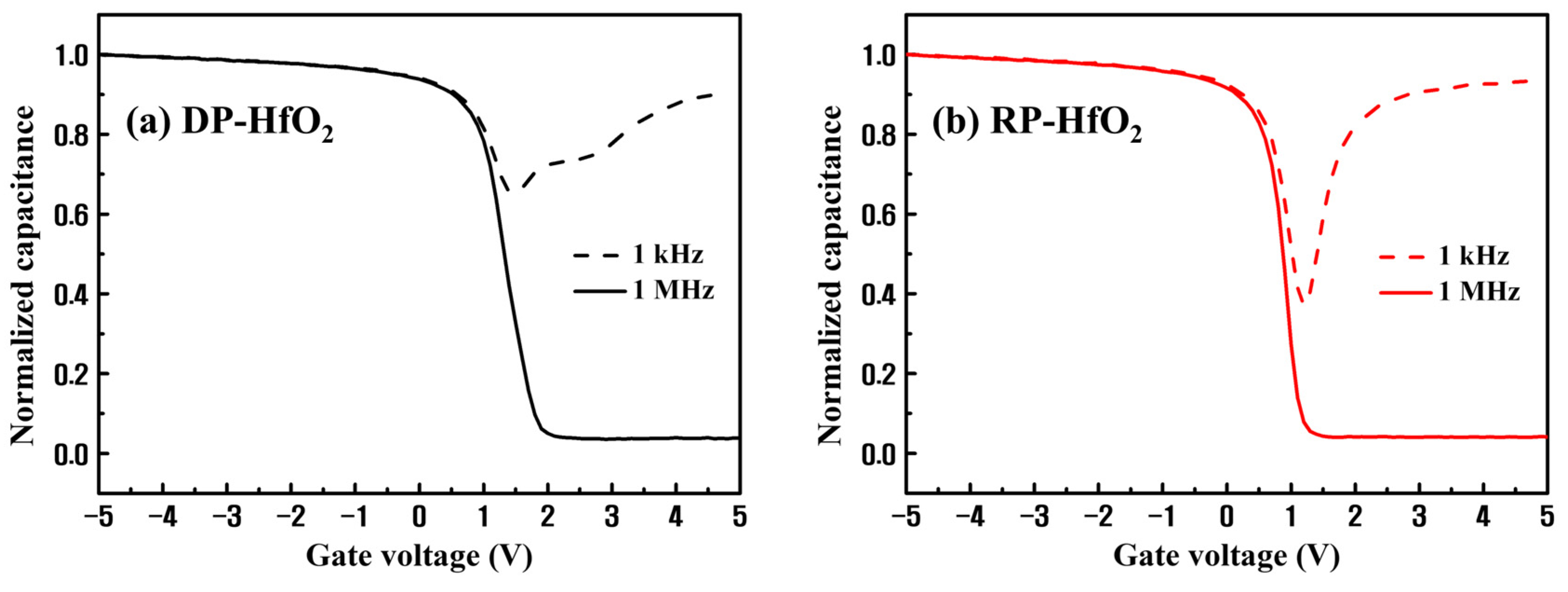
Figure 6 depicts the C–V measurement results at high (1 MHz) and low frequencies (1 kHz) for the DP- and RP-HfO2 CTM devices. Initially, the interface defects between HfO2 and Si extend the voltage direction of the curve. This indicates that an additional charge or voltage must be applied to fill the traps at the interface to achieve the same surface potential or band bending as that without the interface defects. The defects can be present at both interfaces of the HfSiOx layer. Among them, the defects at the HfSiOx/Si interface have a more pronounced impact on the Si channel. Moreover, interface defects create a gap between the low- and high-frequency curves at the point Vmin just before the occurrence of strong inversion [43,44]. This difference is proportional to the interface defect density Dit; Dit can be quantified by the high- and low-frequency capacitance method suggested by Castagné and Vapaille [45]:
D i t = C o x q 2 C l f / C o x 1 C l f / C o x C h f / C o x 1 C h f / C o x
where Clf and Chf are the measured capacitances at low and high frequencies, respectively. The midgap Dit values of the DP- and RP-HfO2 CTM devices evaluated using Equation (3) are 5.53 × 10¹² and 1.18 × 1012 cm−2·eV−1, respectively. The Dit value of the DP-HfO2 CTM device is approximately five times that of the RP-HfO2 CTM device, which is in appropriate agreement with the abovementioned I–V characteristics and CCS measurement results of the DP- and RP-HfO2 thin films.
Figure 7 shows a comparison of the variations of C–V characteristics and ∆VFB values of the DP- and RP-HfO2 CTM devices with respect to the sweeping voltage. The RP-HfO2 CTM device demonstrated wide ∆VFB values of 3.25 and 12.66 V at the operating voltages of ±6 and ±12 V, respectively. In contrast, the DP-HfO2 CTM device exhibited the ∆VFB values of 0.49 and 7.48 V at ±6 and ±12 V, respectively. ∆VFB of the RP-HfO2 CTM device demonstrated a high linearity in proportion to increasing sweeping voltage. This suggests that multiple levels of charge-storage nonvolatile memory can be implemented in this device [18].
Table 1 presents a comparison of the memory characteristics of previously reported high-k oxide-based CTM devices with those of the RP-HfO2 CTM devices fabricated herein. The CTM device synthesized in this study exhibits the highest ∆VFB characteristics even at lower annealing temperatures and lower drive voltages as compared to those of the previously reported devices.
Applicabilities of the CTM devices to practical nonvolatile memory devices were determined via electrical measurements. The CTM capacitor structure demonstrates the ability to evaluate the electrical characteristics of the gate structure via a simple process and has a short fabrication time. Nevertheless, contrary to the transistor structure, which has a source and drain to facilitate the supply of minority carriers to the gate channel, the capacitor structure provides minority carriers to the channel via thermal generation. Therefore, the formation of the inversion layer is very slow. Consequently, the production and charging of minority carriers during programmable gate voltage application in an n-channel capacitor does not match the speed of the gate bias pulse. This can lead to inaccurate measurements of the P/E speed associated with the minority carriers [49]. To address this issue, we irradiated the device with light during the P/E speed measurement. The light irradiation source was a blue spectrum light-emitting diode lamp. During light irradiation, electron–hole pairs were generated around the capacitor, and the photogenerated electrons diffused into the channel region at the base of the gate structure, rapidly forming an inversion layer in response to the gate voltage pulse. Herein, the time required for the formation of the inversion layer follows the relaxation time τ of the dielectric constant model proposed by Debye. Using this model, an expression for the capacitance Cinv in the inversion region as a function of frequency can be obtained as follows [50]:
C i n v ω = C h f + C q e C h f 1 + ( ω τ ) 2
where ω is the angular frequency and Cqe and Chf are the capacitances at quasi-static and high frequencies, respectively. Figure 8a shows the relaxation time as a function of light irradiance (Pa) for the DP- and RP-HfO2 CTM devices. For both devices, τ decreased with an increase in Pa and saturated at approximately 0.5 μs. For accurate P/E measurements, Pa should be sufficiently large such that τ would reach the saturation value. Accordingly, the P/E speeds of the DP- and RP-HfO2 CTM devices were measured at Pa = 30 mW/cm2. The magnitude of the applied gate voltage was 10 V. Figure 8b depicts the variations of the program speeds of the DP- and RP-HfO2 CTM devices with and without light irradiation. The program speeds of the CTM devices evaluated under light irradiation were considerably higher than those measured in the dark room. Figure 8c shows the P/E speeds of the DP- and RP-HfO2 CTM devices under light irradiation. The RP-HfO2 CTM device demonstrated ∆VFB values of 2.01 and 5.07 V at the voltage application times of 10−4 and 10−2 s, respectively, due to its excellent charge trapping properties.
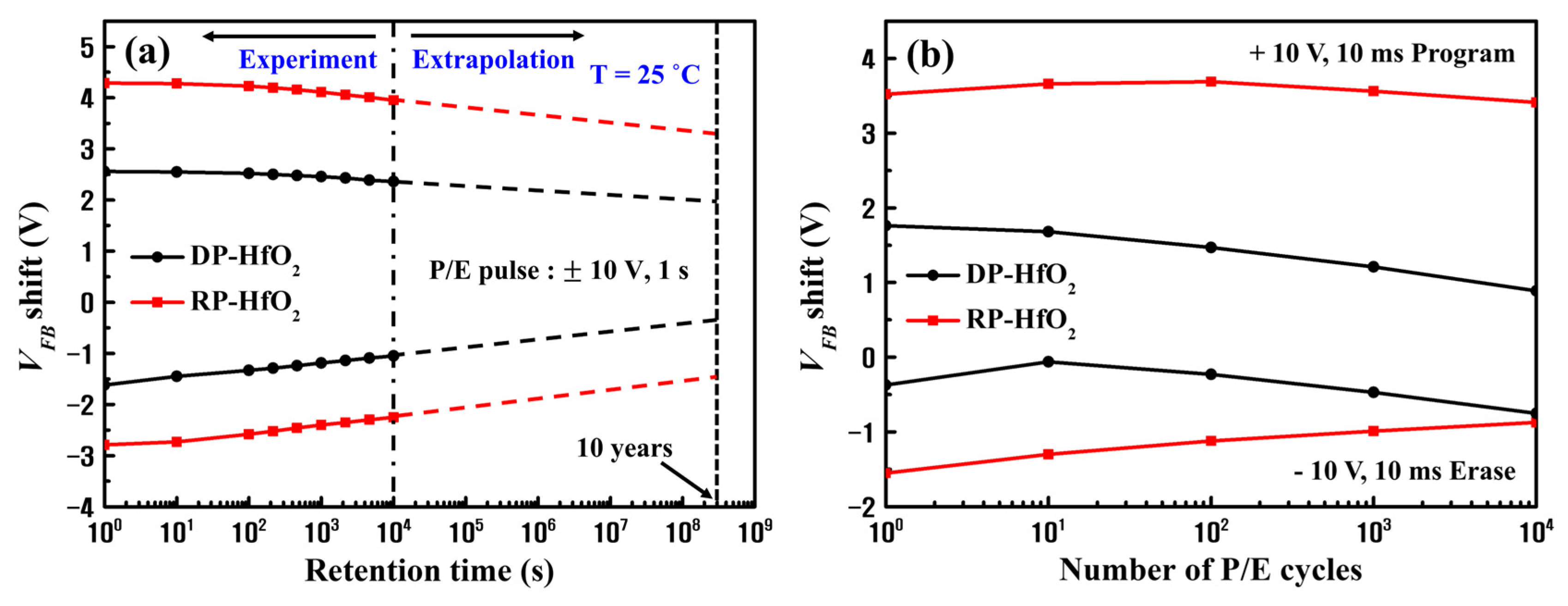
To evaluate the reliability characteristics of the fabricated DP and RP-HfO2 CTM devices, we measured the VFB shift as a function of memory retention time and P/E cycle. ∆VFB values of the synthesized CTM devices decreased with an increase in the memory retention time (Figure 9a). The voltage application conditions were set as follows: program pulse: 10 V for 1 s and erase pulse: −10 V for 1 s. The logarithmic of memory retention time is depicted in Figure 9a. The logarithmic behavior of the memory retention time was estimated, and the VFB shift for up to 10 years was extrapolated. At room temperature, the ∆VFB of the DP-HfO2 CTM device decreased by 46.89% over 10 years of memory retention as compared to that for the RP-HfO2 CTM device (34.32%). A larger charge loss occurred in the case of the DP-HfO2 CTM device due to interface defects between the Hf-silicate used as the TO and Si substrate and charge-trapping sites inside the TO, which easily detrapped the charges trapped inside the CTL [40,51]. However, even the RP-HfO2 CTM device demonstrated lower memory retention characteristics than those of previously reported high-k oxide-based CTM devices (Table 1). This is possibly caused by the relatively thin TO and BO as compared to those used in other devices. Further optimization of the structure is expected to enable the fabrication of devices with appropriate ∆VFB and memory retention characteristics. Figure 9b shows the VFB shift as a function of the number of P/E cycles for the DP- and RP-HfO2 CTM devices. P/E cycling was performed using a pulse train of ±10 V and 10 ms. For both DP- and RP-HfO2 CTM devices, the size of the ∆VFB slightly decreased during 104 cycles. Nevertheless, for the DP-HfO2 CTM device, an overall shift of VFB in the negative direction was observed. Based on previous studies, this is believed to be owing to the generation of a fixed oxide charge inside the unstable Hf-silicate interfacial layer of the DP-HfO2 CTM device by the P/E cycling, overall decreasing the VFB [52]. This shift in VFB can cause a cycling-dependent decrease in the reliability of the device during real-world memory operation and should be maximally suppressed [53].

4. Conclusions

Herein, we determined the optimal process temperature for the DPALD and RPALD of HfO2 thin films and analyzed the influences of the plasma application method on the charge trapping properties of HfO2 thin films and properties of the interface between Si and HfO2 via various techniques. Subsequently, we fabricated CTM devices utilizing the deposited thin films as CTLs and evaluated their memory properties. The DP-HfO2 thin films exhibited relatively constant leakage current and breakdown voltage over the temperature range within the process window. However, the RP-HfO2 thin films demonstrated the lowest leakage current and highest breakdown voltage at an optimal process temperature within the process window. Thereafter, MIS capacitors were synthesized using the HfO2 thin films deposited at an optimal temperature of 220 °C, and C–V measurements were conducted. The results indicated higher ∆VFB characteristics of the RP-HfO2 MIS capacitors than those of the DP-HfO2 MIS capacitors. XPS depth profiling and CCS measurements were used to investigate the difference between the charge trapping properties of DP- and RP-HfO2 thin films; we discovered that the DP-HfO2 films contained many defects in the bulk and at the interface due to in-film damage caused by DP and an unstable interfacial reaction of HfO2 with Si. The memory characteristics of the RP-HfO2 CTM devices were excellent. Particularly, the ∆VFB of these devices was considerably large (±12.66 V) at an operating voltage of 12 V, suggesting that the RP-HfO2 CTM device may be suitable for future implementations of multiple levels of charge-storage nonvolatile memories. Moreover, the RP-HfO2 thin film shows promise for synaptic devices that demonstrate linear potentiation characteristics, provided an appropriate input pulse signal is utilized, owing to its high charge trapping density and low interface trap charge.

Author Contributions

Conceptualization, S.-H.U. and H.-C.L.; methodology, J.-H.Y. and S.-W.K.; software, J.-H.Y.; validation, S.-W.K., J.-H.L. and S.-H.U.; formal analysis, J.-H.Y. and S.-W.K.; investigation, W.-J.P. and G.-R.L.; resources, W.-J.P. and G.-R.L.; data curation, J.-H.Y. and W.-J.P.; writing—original draft preparation, J.-H.Y.; writing—review and editing, J.-H.K., J.-H.L. and H.-C.L.; visualization, W.-J.P. and G.-R.L.; supervision, S.-H.U. and H.-C.L.; project administration, H.-C.L.; funding acquisition, J.-H.K. and H.-C.L. All authors have read and agreed to the published version of the manuscript.

Funding

This research was funded by EN2CORE Technology, Inc. (R&D project “Application of Remote Plasma Process to Semiconductor Memory Devices”), the Priority Research Centers Program (2017R1A6A1A03015562) through the National Research Foundation (NRF) of Korea funded by the Ministry of Education, and the industrial technology innovation program (Grant No. 20006408) funded by the Ministry of Trade, Industry, and Energy (MOTIE), Republic of Korea.

Data Availability Statement

The data presented in this study are contained within the article.

Conflicts of Interest

The authors declare no conflict of interest.

References

  1. Zhao, C.; Zhao, C.Z.; Taylor, S.; Chalker, P.R. Review on non-volatile memory with high-k dielectrics: Flash for generation beyond 32 nm. Materials 2014, 7, 5117–5145. [Google Scholar] [CrossRef] [PubMed]
  2. Li, D.H.; Yun, J.-G.; Lee, J.H.; Park, B.-G. Scaling behaviors of silicon-nitride layer for charge-trapping memory. J. Vac. Sci. Technol. A Vac. Surf. Films 2010, 28, 675–678. [Google Scholar] [CrossRef]
  3. Jung, M.-H.; Kim, K.-S.; Park, G.-H.; Cho, W.-J. Dependence of charge trapping and tunneling on the silicon-nitride (Si3N4) thickness for tunnel barrier engineered nonvolatile memory applications. Appl. Phys. Lett. 2009, 94, 053508. [Google Scholar] [CrossRef]
  4. Melde, T.; Beug, M.F.; Bach, L.; Riedel, S.; Ludwig, C.; Mikolaijck, T. Nitride Thickness Scaling Limitations in TANOS Charge Trapping Devices. In Proceedings of the 2008 Joint Non-Volatile Semiconductor Memory Workshop and International Conference on Memory Technology and Design, Opio, France, 18–22 May 2008. [Google Scholar] [CrossRef]
  5. Zhang, Y.; Shao, Y.Y.; Lu, X.B.; Zeng, M.; Zhang, Z.; Gao, X.S.; Zhang, X.J.; Liu, J.-M.; Dai, J.Y. Defect states and charge trapping characteristics of HfO2 films for high performance nonvolatile memory applications. Appl. Phys. Lett. 2014, 105, 172902. [Google Scholar] [CrossRef]
  6. Nakata, S.; Kato, T.; Ozaki, S.; Kawae, T.; Morimoto, A. Improvement of charge trapping characteristics of Al2O3/Al-rich Al2O3/SiO2 stacked films by thermal annealing. Thin Solid Films 2013, 542, 242–245. [Google Scholar] [CrossRef]
  7. Jiang, K.; Ou, X.; Lan, X.X.; Cao, Z.Y.; Liu, X.J.; Lu, W.; Gong, C.J.; Xu, B.; Li, A.D.; Xia, Y.D.; et al. Remarkable charge-trapping efficiency of the memory device with (TiO2)0.8(Al2O3)0.1 composite charge-storage dielectric. Appl. Phys. Lett. 2014, 104, 263506. [Google Scholar] [CrossRef]
  8. Na, S.-Y.; Yoon, S.-M. Impacts of HfO2/ZnO stack-structured charge-trap layers controlled by atomic layer deposition on nonvolatile memory characteristics of In-Ga-Zn-O channel charge-trap memory thin-film transistors. IEEE J. Electron Devices Soc. 2019, 7, 453–461. [Google Scholar] [CrossRef]
  9. Liu, J.; Wang, Q.; Long, S.; Zhang, M.; Liu, M. A metal/Al2O3/ZrO2/SiO2/Si (MAZOS) structure for high-performance non-volatile memory application. Semicond. Sci. Technol. 2010, 25, 055013. [Google Scholar] [CrossRef]
  10. Palade, C.; Slav, A.; Stavarache, I.; Maraloiu, V.A.; Negrila, C.; Ciurea, M.L. Memory properties of Zr doped ZrO2 MOS-like capacitor. Coatings 2022, 12, 1369. [Google Scholar] [CrossRef]
  11. Tang, Z.; Liu, Z.; Zhu, X. Progress of high-k dielectrics applicable to SONOS-type nonvolatile semiconductor memories. Trans. Electr. Electron. Mater. 2010, 11, 155–165. [Google Scholar] [CrossRef]
  12. Kim, H.; Woo, S.; Kim, H.; Bang, S.; Kim, Y.; Choi, D.; Jeon, H. Pt nanocrystals embedded in remote plasma atomic-layer-deposited HfO2 for nonvolatile memory devices. Electrochem. Solid-State Lett. 2009, 12, H92. [Google Scholar] [CrossRef]
  13. Lee, J.S. Recent progress in gold nanoparticle-based non-volatile memory devices. Gold Bull. 2010, 43, 189–199. [Google Scholar] [CrossRef]
  14. Tang, Z.; Xu, H.; Li, H.; Chen, Y.; Xia, Y.; Yin, J.; Zhu, X.; Liu, Z.; Li, A.; Yan, F. Enhanced charge storage characteristics by ZrO2 nanocrystallites precipitated from amorphous (ZrO2)0.8(SiO2)0.2 charge trapping layer. Microelectron. Eng. 2011, 88, 3227–3230. [Google Scholar] [CrossRef]
  15. Almeida, A.J.; Sahu, A.; Riedinger, A.; Norris, D.J.; Brandt, M.S.; Stutzmann, M.; Pereira, R.N. Charge trapping defects in CdSe nanocrystal quantum dots. J. Phys. Chem. C 2016, 120, 13763–13770. [Google Scholar] [CrossRef]
  16. Stavarache, I.; Cojocaru, O.; Maraloiu, V.A.; Teodorescu, V.S.; Stoica, T.; Ciurea, M.L. Effects of Ge-related storage centers formation in Al2O3 enhancing the performance of floating gate memories. Appl. Surf. Sci. 2021, 542, 148702. [Google Scholar] [CrossRef]
  17. Palade, C.; Slav, A.; Lepadatu, A.M.; Stavarache, I.; Dascalescu, I.; Maraloiu, V.A.; Negrila, C.; Logafatu, C.; Stoica, T.; Teodorescu, V.S.; et al. Orthorhombic HfO2 with embedded Ge nanoparticles in nonvolatile memories used for the detection of ionizing radiation. Nanotechnology 2019, 30, 065010. [Google Scholar] [CrossRef]
  18. Maikap, S.; Lee, H.Y.; Wang, T.-Y.; Tzeng, P.-J.; Wang, C.C.; Lee, L.S.; Liu, K.C.; Yang, J.-R.; Tsai, M.-J. Charge trapping characteristics of atomic-layer-deposited HfO2 films with Al2O3 as a blocking oxide for high-density non-volatile memory device applications. Semicond. Sci. Technol. 2007, 22, 884. [Google Scholar] [CrossRef]
  19. Spiga, S.; Driussi, F.; Lamperti, A.; Congedo, G.; Salicio, O. Effects of thermal treatments on the trapping properties of HfO2 films for charge trap memories. Appl. Phys. Express 2012, 5, 021102. [Google Scholar] [CrossRef]
  20. Martínez-Puente, M.A.; Horley, P.; Aguirre-Tostado, F.S.; López-Medina, J.; Borbón-Nuñez, H.A.; Tiznado, H.; Susarrey-Arce, A.; Martínez-Guerra, E. ALD and PEALD deposition of HfO2 and its effects on the nature of oxygen vacancies. Mater. Sci. Eng. B Solid State Mater. Adv. Technol. 2022, 285, 115964. [Google Scholar] [CrossRef]
  21. Park, P.K.; Roh, J.-S.; Choi, B.H.; Kang, S.-W. Interfacial layer properties of HfO2 films formed by plasma-enhanced atomic layer deposition on silicon. Electrochem. Solid-State Lett. 2006, 9, F34. [Google Scholar] [CrossRef]
  22. Kim, K.; Oh, I.-K.; Kim, H.; Lee, Z. Atomic-scale characterization of plasma-induced damage in plasma-enhanced atomic layer deposition. Appl. Surf. Sci. 2017, 425, 781–787. [Google Scholar] [CrossRef]
  23. Fischer, D.D.; Knaut, M.; Reif, J.; Nehm, F.; Albert, M.; Bartha, J.W. Direct plasma-enhanced atomic layer deposition of aluminum nitride for water permeation barriers. J. Vac. Sci. Technol. A Vac. Surf. Films 2020, 38, 022419. [Google Scholar] [CrossRef]
  24. Price, K.M.; Najmaei, S.; Ekuma, C.E.; Burke, R.A.; Dubey, M.; Franklin, A.D. Plasma-enhanced atomic layer deposition of HfO2 on monolayer, bilayer, and trilayer MoS2 for the integration of high-κ dielectrics in two-dimensional devices. ACS Appl. Nano Mater. 2019, 2, 4085–4094. [Google Scholar] [CrossRef]
  25. Profijt, H.B.; Potts, S.E.; van de Sanden, M.C.M.; Kessels, W.M.M. Plasma-assisted atomic layer deposition: Basics, opportunities, and challenges. J. Vac. Sci. Technol. A Vac. Surf. Films 2011, 29, 050801. [Google Scholar] [CrossRef]
  26. Heil, S.B.S.; van Hemmen, J.L.; Hodson, C.J.; Singh, N.; Klootwijk, J.H.; Roozeboom, F.; van de Sanden, M.C.M.; Kessels, W.M.M. Deposition of TiN and HfO2 in a commercial 200 mm remote plasma atomic layer deposition reactor. J. Vac. Sci. Technol. A Vac. Surf. Films 2007, 25, 1357–1366. [Google Scholar] [CrossRef]
  27. Kim, H.-G.; Hong, D.-H.; Yoo, J.-H.; Lee, H.-C. Effect of process temperature on density and electrical characteristics of Hf0.5Zr0.5O2 thin films prepared by plasma-enhanced atomic layer deposition. Nanomaterials 2022, 12, 548. [Google Scholar] [CrossRef]
  28. Hong, D.H.; Yoo, J.H.; Park, W.J.; Kim, S.W.; Kim, J.H.; Uhm, S.H.; Lee, H.C. Characteristics of Hf0.5Zr0.5O2 thin films prepared by direct and remote plasma atomic layer deposition for application to ferroelectric memory. Nanomaterials 2023, 13, 900. [Google Scholar] [CrossRef]
  29. You, H.-W.; Cho, W.-J. Charge trapping properties of the HfO2 layer with various thicknesses for charge trap flash memory applications. Appl. Phys. Lett. 2010, 96, 093506. [Google Scholar] [CrossRef]
  30. Shen, Y.; Zhang, Z.; Zhang, Q.; Wei, F.; Yin, H.; Wei, Q.; Men, K. A Gd-doped HfO2 single film for a charge trapping memory device with a large memory window under a low voltage. RSC Adv. 2020, 10, 7812–7816. [Google Scholar] [CrossRef]
  31. Xiong, K.; Robertson, J.; Gibson, M.C.; Clark, S.J. Defect energy levels in HfO2 high-dielectric-constant gate oxide. Appl. Phys. Lett. 2005, 87, 183505. [Google Scholar] [CrossRef]
  32. Major, G.H.; Farley, N.; Sherwood, P.M.A.; Linford, M.R.; Terry, J.; Fernandez, V.; Artyushkova, K. Practical guide for curve fitting in X-ray photoelectron spectroscopy. J. Vac. Sci. Technol. A Vac. Surf. Films 2020, 38, 061203. [Google Scholar] [CrossRef]
  33. Morant, C.; Galán, L.; Sanz, J.M. An XPS study of the initial stages of oxidation of hafnium. Surf. Interface Anal. 1990, 16, 304–308. [Google Scholar] [CrossRef]
  34. Sharath, S.U.; Kurian, J.; Komissinskiy, P.; Hildebrandt, E.; Bertaud, T.; Walczyk, C.; Calka, P.; Schroeder, T.; Alff, L. Thickness independent reduced forming voltage in oxygen engineered HfO2 based resistive switching memories. Appl. Phys. Lett. 2014, 105, 073505. [Google Scholar] [CrossRef]
  35. Driemeier, C.; Wallace, R.M.; Baumvol, I.J.R. Oxygen species in HfO2 films: An in situ X-ray photoelectron spectroscopy study. J. Appl. Phys. Chem. 2007, 102, 024112. [Google Scholar] [CrossRef]
  36. Bera, M.K.; Maiti, C.K. Electrical properties of SiO2/TiO2 high-k gate dielectric stack. Mater. Sci. Semicond. Process. 2006, 9, 909–917. [Google Scholar] [CrossRef]
  37. Liu, Z.H.; Lai, P.T.; Cheng, Y.C. Characterization of charge trapping and high-field endurance for 15-nm thermally nitrided oxides. IEEE Trans. Electron Devices 1991, 38, 344–354. [Google Scholar] [CrossRef]
  38. Lee, J.-C.; Oh, S.-J.; Cho, M.; Hwang, C.S.; Jung, R. Chemical structure of the interface in ultrathin HfO2/Si films. Appl. Phys. Lett. 2004, 84, 1305–1307. [Google Scholar] [CrossRef]
  39. Kim, J.; Kim, S.; Jeon, H.; Cho, M.-H.; Chung, K.-B.; Bae, C. Characteristics of HfO2 thin films grown by plasma atomic layer deposition. Appl. Phys. Lett. 2005, 87, 053108. [Google Scholar] [CrossRef]
  40. An, H.-M.; Kim, H.-D.; Kim, T.G. Analysis of the energy distribution of interface traps related to tunnel oxide degradation using charge pumping techniques for 3D NAND flash applications. Mater. Res. Bull. 2013, 48, 5084–5087. [Google Scholar] [CrossRef]
  41. Shen, Y.-S.; Chen, K.-Y.; Chen, P.-C.; Chen, T.-C.; Wu, Y.-H. Flash memory featuring low-voltage operation by crystalline ZrTiO4 charge-trapping layer. Sci. Rep. 2017, 7, 43659. [Google Scholar] [CrossRef]
  42. Nyns, L.; Ragnarsson, L.-Å.; Hall, L.; Delabie, A.; Heyns, M.; Van Elshocht, S.; Vinckier, C.; Zimmerman, P.; De Gendt, S. Silicon orientation effects in the atomic layer deposition of hafnium oxide. J. Electrochem. Soc. 2008, 155, G9. [Google Scholar] [CrossRef]
  43. Sze, S.M.; Ng, K.K. Physics of Semiconductor Devices, 3rd ed.; John Wiley & Sons: Hoboken, NJ, USA, 2006. [Google Scholar]
  44. Engel-Herbert, R.; Hwang, Y.; Stemmer, S. Comparison of methods to quantify interface trap densities at dielectric/III-V semiconductor interfaces. J. Appl. Phys. 2010, 108, 124101. [Google Scholar] [CrossRef]
  45. Castagné, R.; Vapaille, A. Description of the SiO2 Si interface properties by means of very low frequency MOS capacitance measurements. Surf. Sci. 1971, 28, 157–193. [Google Scholar] [CrossRef]
  46. Lan, X.; Gong, C.; Ou, X.; Cao, Y.; Sun, C.; Chen, Y.; Xu, B.; Xia, Y.; Li, A.; Yin, J.; et al. Enhancement of the charge trapping performances with HfAlO composite oxide thin films in SONOS-type nonvolatile memory. Microelectron. Eng. 2015, 133, 88–91. [Google Scholar] [CrossRef]
  47. Yoon, G.; Kim, T.; Agrawal, K.; Kim, J.; Park, J.; Kim, H.-H.; Cho, E.-C.; Yi, J. Optimization of MIS type non-volatile memory device with Al-doped HfO2 as charge trapping layer. ECS J. Solid State Sci. Technol. 2020, 9, 075004. [Google Scholar] [CrossRef]
  48. Yoo, J.; Kim, S.; Jeon, W.; Park, A.; Choi, D.; Choi, B. A study on the charge trapping characteristics of high-k laminated traps. IEEE Electron Device Lett. 2019, 40, 1427–1430. [Google Scholar] [CrossRef]
  49. Jin, L.; Zhang, M.-H.; Huo, Z.-L.; Wang, Y.; Yu, Z.-A.; Jiang, D.-D.; Chen, J.-N.; Liu, M. A simple and accurate method for measuring program/erase speed in a memory capacitor structure. Chin. Phys. B 2013, 22, 018501. [Google Scholar] [CrossRef]
  50. Gildenblat, G.; Zhu, Z.; Wu, W. Analytical expression for the bias and frequency-dependent capacitance of MOS varactors. IEEE Trans. Electron Devices 2007, 54, 3107–3108. [Google Scholar] [CrossRef]
  51. Tzeng, S.-D.; Gwo, S. Charge trapping properties at silicon nitride/silicon oxide interface studied by variable-temperature electrostatic force microscopy. J. Appl. Phys. 2006, 100, 023711. [Google Scholar] [CrossRef]
  52. Lun, Z.; Wang, T.; Zeng, L.; Zhao, K.; Liu, X.; Wang, Y.; Kang, J.; Du, G. Simulation on Endurance Characteristic of Charge Trapping Memory. In Proceedings of the 2013 International Conference on Simulation of Semiconductor Processes and Devices (SISPAD), Glasgow, UK, 3–5 September 2013. [Google Scholar] [CrossRef]
  53. Gong, N.; Ma, T.-P. A study of endurance issues in HfO2-based ferroelectric field effect transistors: Charge trapping and trap generation. IEEE Electron Device Lett. 2018, 39, 15–18. [Google Scholar] [CrossRef]
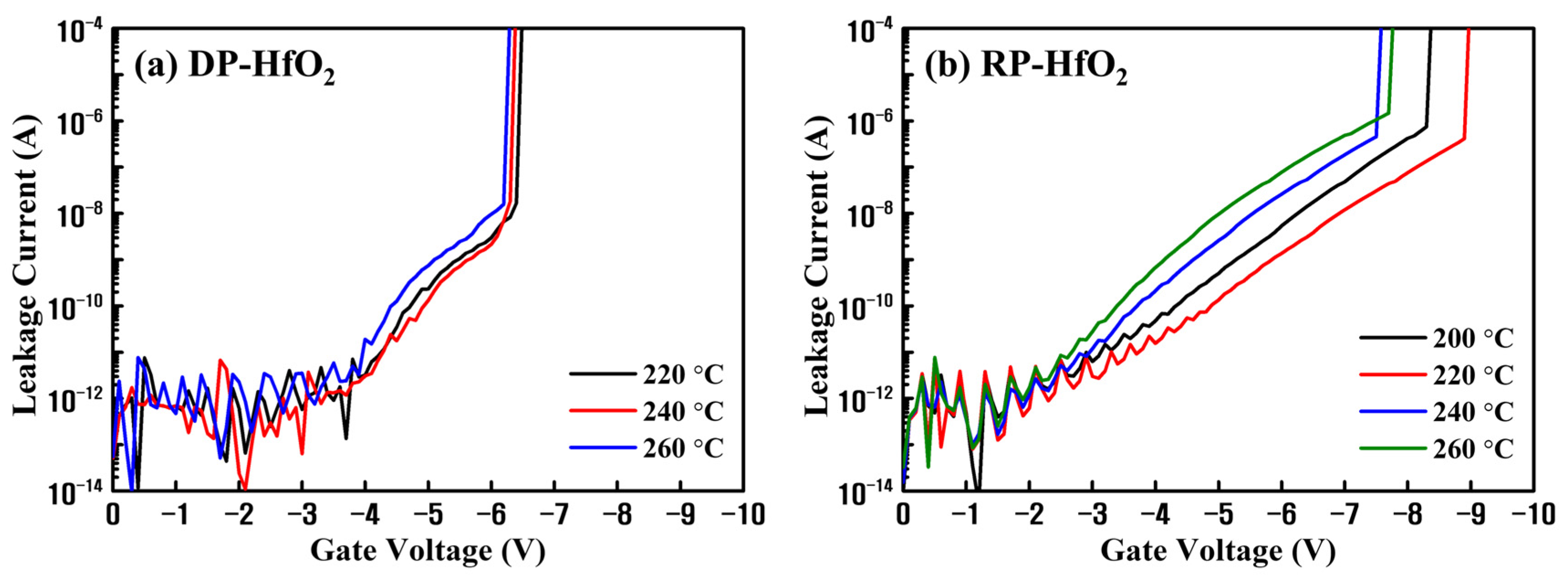
Figure 1. Current–voltage (I–V) characteristics of the HfO2 metal–insulator–semiconductor (MIS) capacitors based on the films deposited by (a) direct-plasma (DP) atomic layer deposition (ALD) (DPALD) and (b) remote plasma (RP) ALD (RPALD) as functions of deposition temperature.
Nanomaterials 13 01785 g001
Figure 2. Capacitance–voltage (C–V) characteristics of (a) DP- and (b) RP-HfO2 MIS capacitors as functions of the sweeping voltage and (c) the corresponding memory windows.
Nanomaterials 13 01785 g002
Figure 3. Comparison of (a,b) X-ray photoelectron spectroscopy (XPS) depth profiling, and (c,d) Hf 4f and (e,f) O 1s narrow scan XPS patterns of DP- and RP-HfO2 thin films.
Nanomaterials 13 01785 g003
Figure 4. (a) Constant current stress measurements and (b) electron band diagrams including the trap centroids of DP- and RP-HfO2 MIS capacitors.
Nanomaterials 13 01785 g004
Figure 5. Cross-sectional transmission electron microscopy images of (a) DP- and (b) RP-HfO2 charge-trapping memory (CTM) devices.
Nanomaterials 13 01785 g005
Figure 6. C–V measurement results of (a) DP- and (b) RP-HfO2 CTM devices at high (1 MHz) and low frequencies (1 kHz).
Nanomaterials 13 01785 g006
Figure 7. C–V characteristics of (a) DP- and (b) RP-HfO2 CTM devices as functions of sweeping voltage and (c) the corresponding memory windows.
Nanomaterials 13 01785 g007
Figure 8. Comparison of the variations of the (a) relaxation time with respect to light intensity, (b) program speed with and without light irradiation, and (c) program/erase (P/E) rates for DP-HfO2 and RP-HfO2 CTM devices.
Nanomaterials 13 01785 g008
Figure 9. (a) Memory retention times and (b) endurance characteristics of DP- and RP-HfO2 CTM devices.
Nanomaterials 13 01785 g009
Table 1. Comparison among the memory characteristics of high-k-based CTM devices with different structures and compositions.
TO/CTL/BOThickness (nm)Annealing Temp. (°C)Operating Voltage (V)Memory Window (V)Charge Loss (%)References
HfSiOX/RP-HfO2/Al2O32/9/9400±1212.6634.32This work
SiO2/HfO2/Al2O33/10/101000±157.431[18]
SiO2/HfO23/55/0800±105.1-[5]
Al2O3/HfAlO/Al2O32/9/12600±126.2979[46]
Al2O3/HfAlO/Al2O32/10/15450±147.4523.64[47]
SiO2/ZrO2/Al2O35/10/15700±117.116[9]
SiO2/HfAlO/Al2O33/9/8800±1611.514.9[48]
SiO2/Al-rich Al2O3/Al2O33.4/5/6400±128.2-[6]
(Al2O3/SiO2)/Ge/Al2O3(4/3)/15/10700−1~145.4111 (ON), 9.8 (OFF)[16]
Disclaimer/Publisher’s Note: The statements, opinions and data contained in all publications are solely those of the individual author(s) and contributor(s) and not of MDPI and/or the editor(s). MDPI and/or the editor(s) disclaim responsibility for any injury to people or property resulting from any ideas, methods, instructions or products referred to in the content.