
On Improving Wear Resistance of Cr-Al-N Coatings Using Dynamic Glancing Angle DC Magnetron Sputtering


 ,
,  , ,
, ,  ,
,  and
and 
Abstract
:1. Introduction
2. Materials and Methods
3. Results
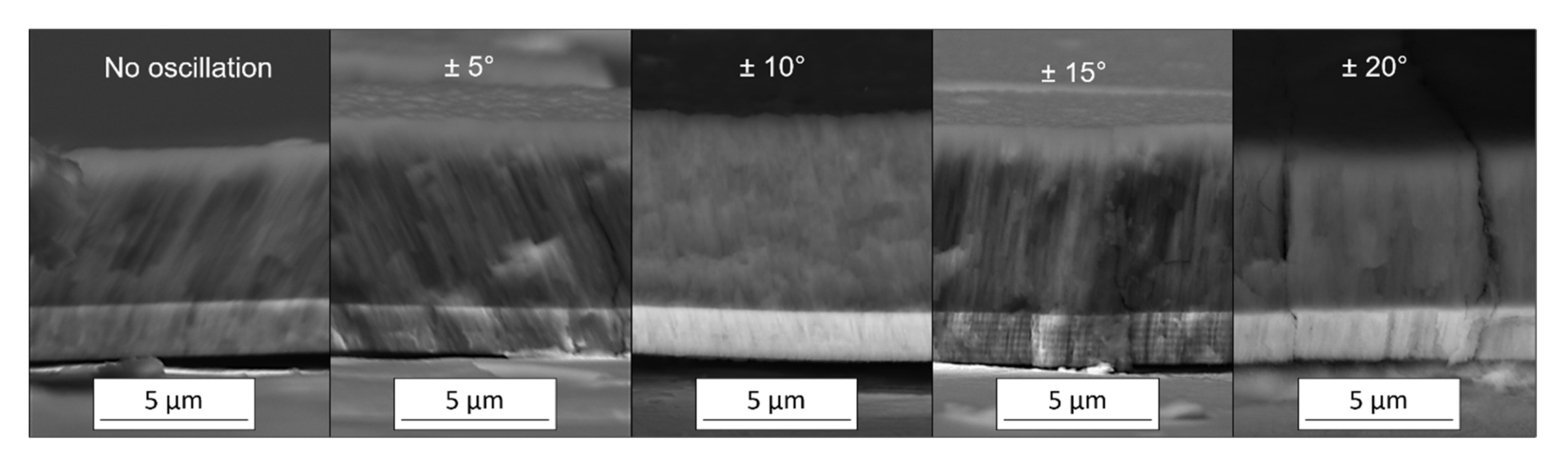
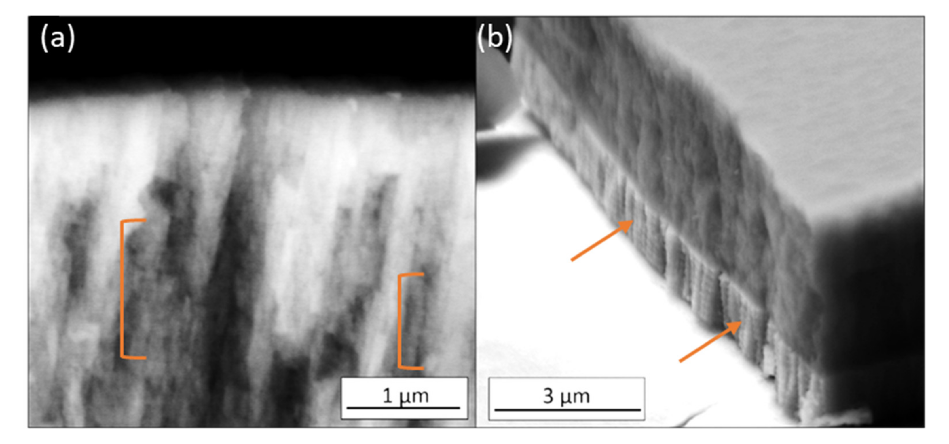
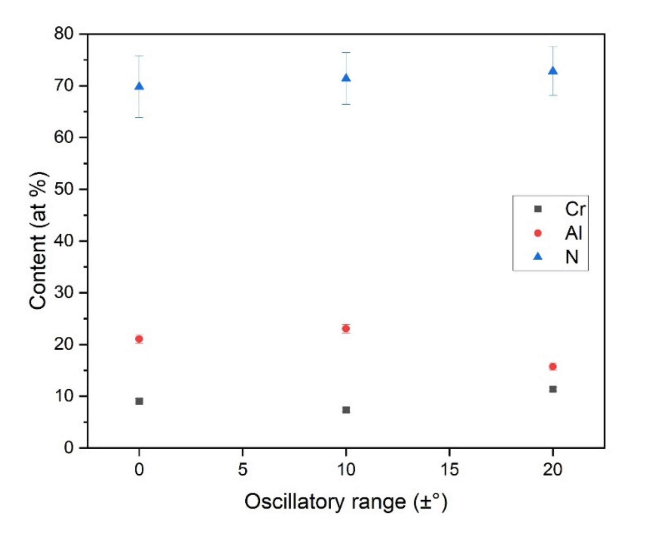
3.1. Morphology, Structure and Chemical Composition
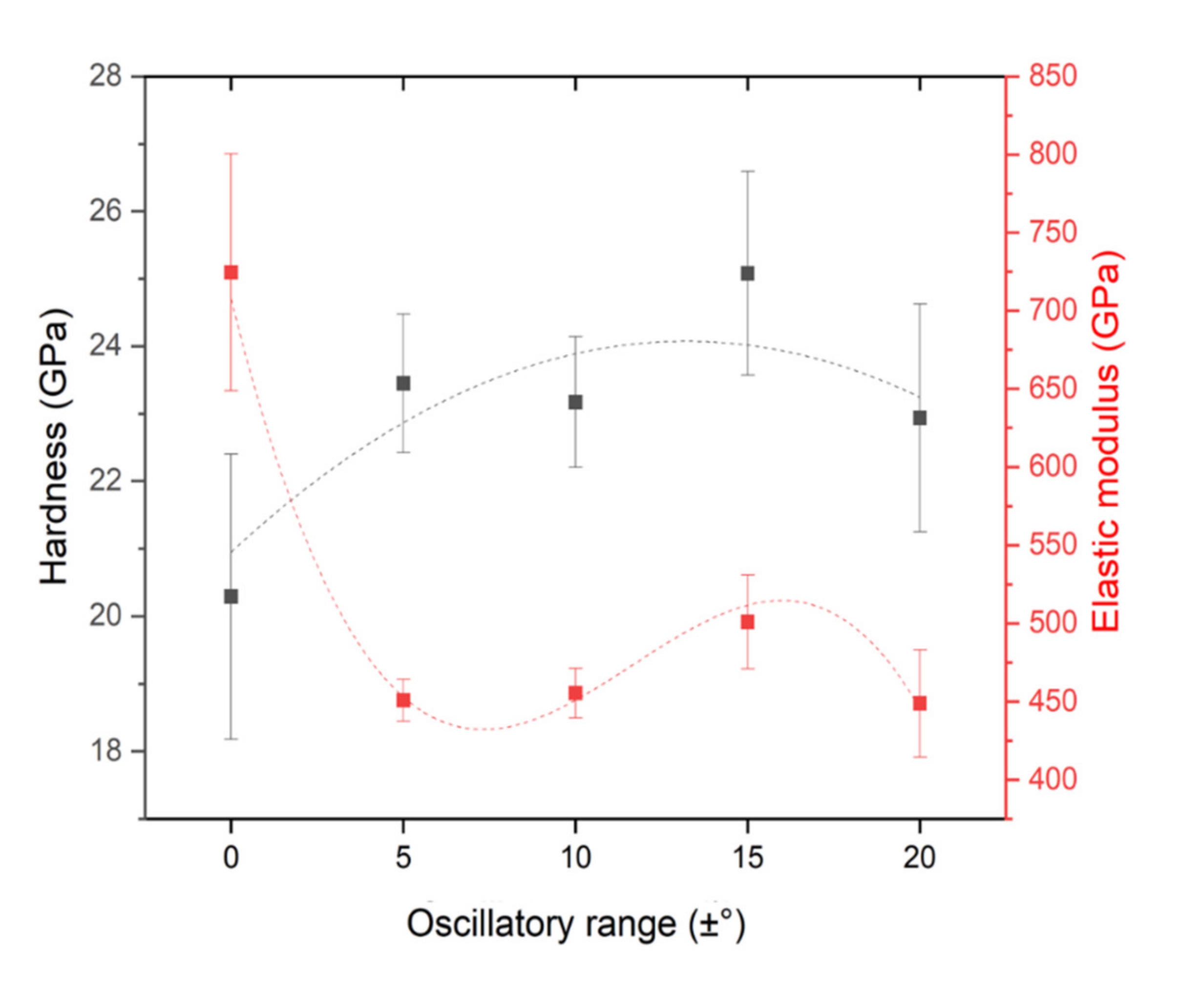
3.2. Mechanical and Wear Performance
4. Discussion
5. Conclusions
- The variations in oscillatory range did not produce any detectable texture or chemical composition change. The deposition rate is dependent on the oscillatory range, being ±10°, the condition with the highest deposition rate.
- Hardness improvement from ~20 up to ~25 GPa was obtained using DGLAD as an effect of the multilayer-like structure formed due to oscillation.
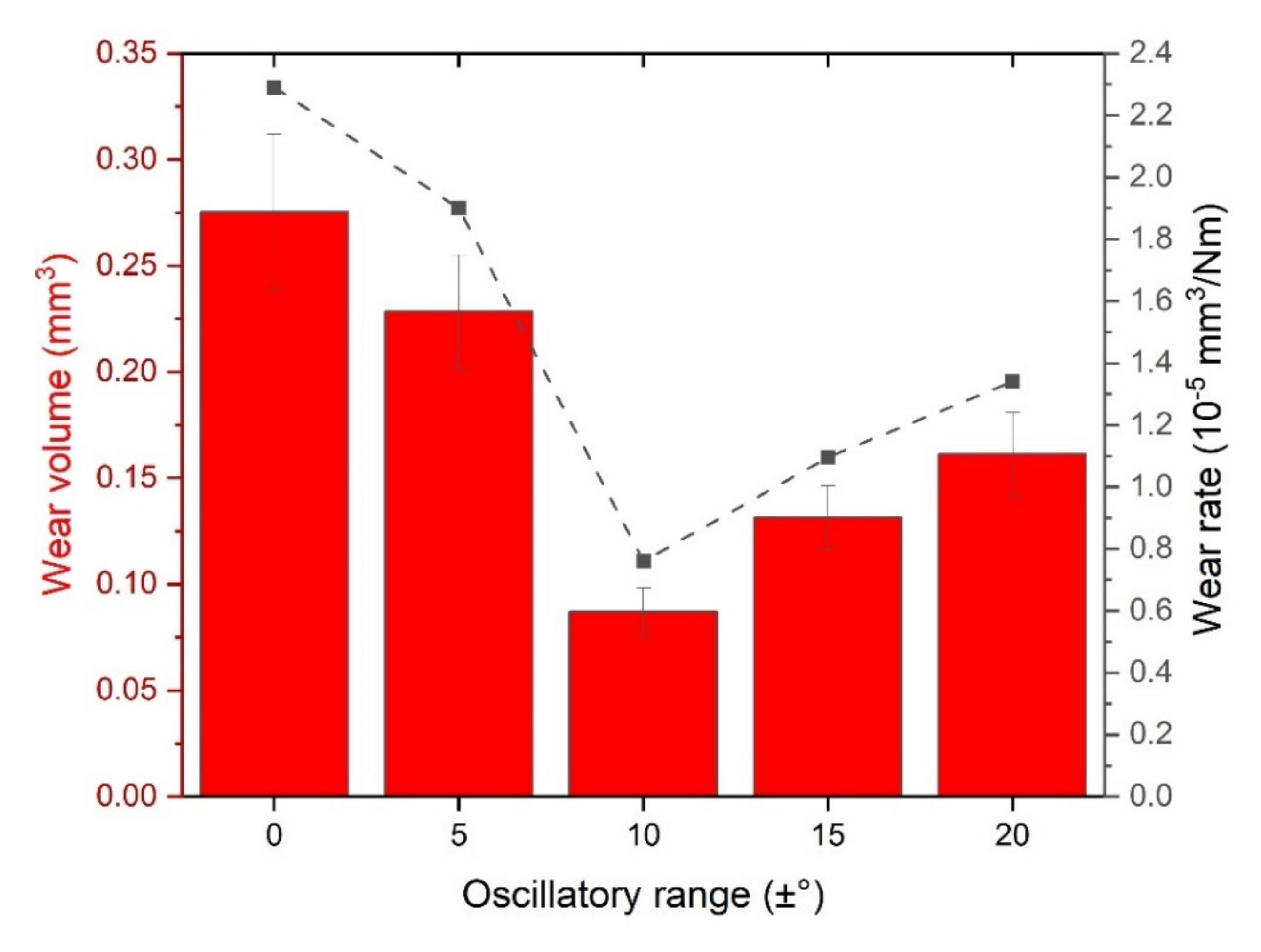
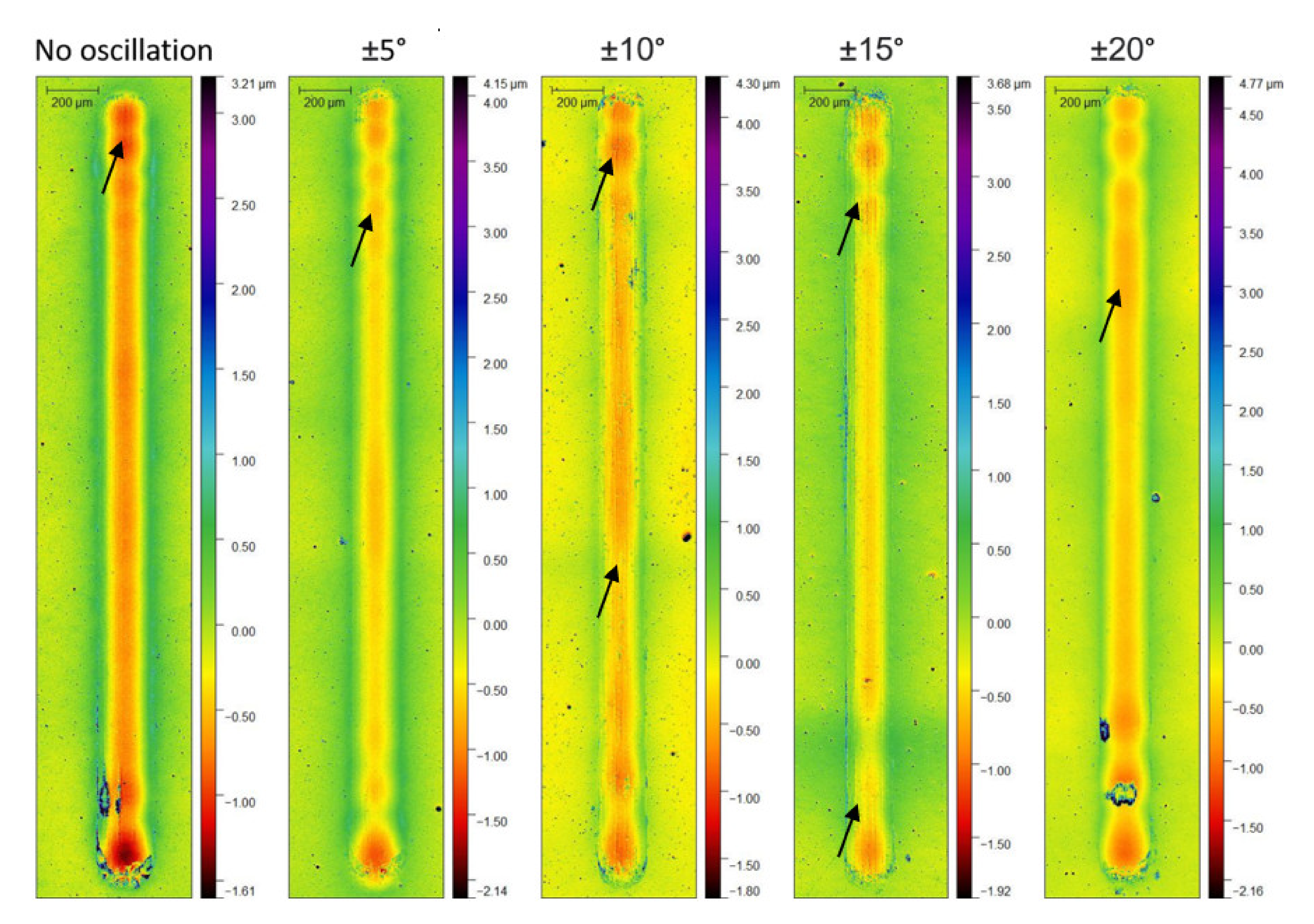
- ±10° oscillatory range produced coatings with best wear performance with about three times less material removed when compared to coatings produced with no oscillation.
- DGLAD is presented as a promising route to manufacture multilayer-like coatings with improved wear resistance capable of reducing energy loss by friction.
Author Contributions
Funding
Institutional Review Board Statement
Informed Consent Statement
Data Availability Statement
Acknowledgments
Conflicts of Interest
References
- Holmberg, K.; Erdemir, A. The impact of tribology on energy use and CO2 emission globally and in combustion engine and electric cars. Tribol. Int. 2019, 135, 389–396. [Google Scholar] [CrossRef]
- Ciulli, E. Tribology and Industry: From the Origins to 4.0. Front. Mech. Eng. 2019, 5, 55. [Google Scholar] [CrossRef] [Green Version]
- Holmberg, K.; Erdemir, A. Influence of tribology on global energy consumption, costs and emissions. Friction 2017, 5, 263–284. [Google Scholar] [CrossRef]
- Mezger, P.R.; Creugers, N.H.J. Titanium nitride coatings in clinical dentistry. J. Dent. 1992, 20, 342–344. [Google Scholar] [CrossRef]
- Hovsepian, P.E.; Ehiasarian, A.P.; Deeming, A.; Schimpf, C. Novel TiAlCN/VCN nanoscale multilayer PVD coatings deposited by the combined high-power impulse magnetron sputtering/unbalanced magnetron sputtering (HIPIMS/UBM) technology. Vacuum 2008, 82, 1312–1317. [Google Scholar] [CrossRef]
- Bräuer, G.; Szyszka, B.; Vergöhl, M.; Bandorf, R. Magnetron sputtering—Milestones of 30 years. Vacuum 2010, 84, 1354–1359. [Google Scholar] [CrossRef]
- Garcia, J.; Pitonak, R.; Weissenbacher, R.; Köpf, A. Production and characterization of wear resistant Ti(C,N) coatings manufactured by modified chemical vapor deposition process. Surf. Coat. Technol. 2010, 205, 2322–2327. [Google Scholar] [CrossRef]
- Ferreira, R.; Carvalho, Ó.; Sobral, L.; Carvalho, S.; Silva, F. Influence of morphology and microstructure on the tribological behavior of arc deposited CrN coatings for the automotive industry. Surf. Coat. Technol. 2020, 397, 126047. [Google Scholar] [CrossRef]
- Bobzin, K.; Lugscheider, E.; Nickel, R.; Bagcivan, N.; Krämer, A. Wear behavior of Cr1-xAlxN PVD-coatings in dry running conditions. Wear 2007, 263, 1274–1280. [Google Scholar] [CrossRef]
- Bagcivan, N.; Bobzin, K.; Theiß, S. ( Cr 1 − x Al x ) N: A comparison of direct current, middle frequency pulsed and high power pulsed magnetron sputtering for injection molding components. Thin Solid Film. 2013, 528, 180–186. [Google Scholar] [CrossRef]
- Sánchez-López, J.C.; Contreras, A.; Domínguez-Meister, S.; García-Luis, A.; Brizuela, M. Tribological behaviour at high temperature of hard CrAlN coatings doped with y or Zr. Thin Solid Film. 2014, 550, 413–420. [Google Scholar] [CrossRef] [Green Version]
- Kelly, P.J.; Arnell, R.D. Magnetron sputtering: A review of recent developments and applications. Vacuum 2000, 56, 159–172. [Google Scholar] [CrossRef]
- Robbie, K.; Brett, M.J. Sculptured thin films and glancing angle deposition: Growth mechanics and applications. J. Vac. Sci. Technol. A Vac. Surf. Film. 1997, 15, 1460–1465. [Google Scholar] [CrossRef]
- Robbie, K. Advanced techniques for glancing angle deposition. J. Vac. Sci. Technol. B Microelectron. Nanometer Struct. Process. Meas. Phenom. 1998, 16, 1115–1122. [Google Scholar] [CrossRef]
- Sit, J.C.; Vick, D.; Robbie, K.; Brett, M.J. Thin film microstructure control using glancing angle deposition by sputtering. J. Mater. Res. 1999, 14, 1197–1199. [Google Scholar] [CrossRef]
- Barranco, A.; Borras, A.; Gonzalez-Elipe, A.R.; Palmero, A. Progress in Materials Science Perspectives on oblique angle deposition of thin films: From fundamentals to devices. Prog. Mater. Sci. 2016, 76, 59–153. [Google Scholar] [CrossRef] [Green Version]
- Abadias, G.; Anğay, F.; Mareus, R.; Mastail, C. Texture and stress evolution in HfN films sputter-deposited at oblique angles. Coatings 2019, 9, 712. [Google Scholar] [CrossRef] [Green Version]
- Rydosz, A.; Dyndał, K.; Andrysiewicz, W.; Grochala, D.; Marszałek, K. GLAD magnetron sputtered ultra-thin copper oxide films for gas-sensing application. Coatings 2020, 10, 378. [Google Scholar] [CrossRef] [Green Version]
- Mukherjee, S.; Gall, D. Structure zone model for extreme shadowing conditions. Thin Solid Film. 2013, 527, 158–163. [Google Scholar] [CrossRef]
- Hawkeye, M.M.; Brett, M.J. Glancing angle deposition: Fabrication, properties, and applications of micro- and nanostructured thin films. J. Vac. Sci. Technol. A Vac. Surf. Film. 2007, 25, 1317–1335. [Google Scholar] [CrossRef]
- Leontyev, V.; Wakefield, N.G.; Tabunshchyk, K.; Sit, J.C.; Brett, M.J.; Kovalenko, A. Selective transmittance of linearly polarized light in thin films rationally designed by FDTD and FDFD theories and fabricated by glancing angle deposition. J. Appl. Phys. 2008, 104, 104302. [Google Scholar] [CrossRef]
- Mansour, M.; Keita, A.S.; Gallas, B.; Rivory, J.; Besnard, A.; Martin, N. Optical anisotropy of tilted columns thin films of chromium deposited at oblique incidence. Opt. Mater. 2010, 32, 1146–1153. [Google Scholar] [CrossRef]
- Keckes, J.; Daniel, R.; Todt, J.; Zalesak, J.; Sartory, B.; Braun, S.; Gluch, J.; Rosenthal, M.; Burghammer, M.; Mitterer, C.; et al. 30 nm X-ray focusing correlates oscillatory stress, texture and structural defect gradients across multilayered TiN-SiOx thin film. Acta Mater. 2018, 144, 862–873. [Google Scholar] [CrossRef]
- Daniel, R.; Meindlhumer, M.; Zalesak, J.; Baumegger, W.; Todt, J.; Ziegelwanger, T.; Keckes, J.F.; Mitterer, C.; Keckes, J. Multi-scale interface design of strong and damage resistant hierarchical nanostructured materials. Mater. Des. 2020, 196, 109169. [Google Scholar] [CrossRef]
- Guimaraes, M.C.R.; de Castilho, B.C.N.M.; de Souza Nossa, T.; Avila, P.R.T.; Cucatti, S.; Alvarez, F.; Garcia, J.L.; Pinto, H.C. On the effect of substrate oscillation on CrN coatings deposited by HiPIMS and dcMS. Surf. Coat. Technol. 2018, 340, 112–120. [Google Scholar] [CrossRef]
- Jimenez, M.J.M.; Antunes, V.; Cucatti, S.; Riul, A.; Zagonel, L.F.; Figueroa, C.A.; Wisnivesky, D.; Alvarez, F. Physical and micro-nano-structure properties of chromium nitride coating deposited by RF sputtering using dynamic glancing angle deposition. Surf. Coat. Technol. 2019, 372, 268–277. [Google Scholar] [CrossRef]
- Jimenez, M.J.M.; Antunes, V.G.; Zagonel, L.F.; Figueroa, C.A.; Wisnivesky, D.; Alvarez, F. Effect of the period of the substrate oscillation in the dynamic glancing angle deposition technique: A columnar periodic nanostructure formation. Surf. Coat. Technol. 2020, 383, 125237. [Google Scholar] [CrossRef]
- Avila, P.R.T.; da Silva, E.P.; Rodrigues, A.M.; Aristizabal, K.; Pineda, F.; Coelho, R.S.; Garcia, J.L.; Soldera, F.; Walczak, M.; Pinto, H.C. On manufacturing multilayer-like nanostructures using misorientation gradients in PVD films. Sci. Rep. 2019, 9, 15898. [Google Scholar] [CrossRef] [Green Version]
- Avila, P.R.T.; Rodrigues, A.M.; Guimarães, M.C.R.; Walczak, M.; Menezes, R.R.; Neves, G.d.A.; Pinto, H.C. Nitrogen-enriched Cr1-xAlxN multilayer-like coatings manufactured by dynamic glancing angle direct current magnetron sputtering. Materials 2020, 13, 3650. [Google Scholar] [CrossRef] [PubMed]
- Pharr, G.M. An improved technique for determining hardness and elastic modulus using load and displacement sensing indentation experiments. J. Mater. Res. 1992, 7, 1564–1583. [Google Scholar] [CrossRef]
- Pelleg, J.; Zevin, L.Z.; Lungo, S.; Croitoru, N. Reactive-sputter-deposited TiN films on glass substrates. Thin Solid Film. 1991, 197, 117–128. [Google Scholar] [CrossRef]
- Anders, A. Deposition rates of high power impulse magnetron sputtering: Physics and economics. J. Vac. Sci. Technol. A Vac. Surf. Film. 2010, 28, 783–790. [Google Scholar] [CrossRef] [Green Version]
- Biswas, B.; Purandare, Y.; Sugumaran, A.A.; Loch, D.A.L.; Creasey, S.; Khan, I.; Ehiasarian, A.P.; Hovsepian, P.E. Defect growth in multilayer chromium nitride/niobium nitride coatings produced by combined high power impulse magnetron sputtering and unbalance magnetron sputtering technique. Thin Solid Film. 2017, 636, 558–566. [Google Scholar] [CrossRef]
- Hutchings, I.; Shipway, P. Tribology: Friction and Wear of Engineering Materials, 2nd ed.; Butterworth-Heinemann: Oxford, UK, 2017; ISBN 9780081009109. [Google Scholar]
- Tsui, T.Y.; Pharr, G.M.; Oliver, W.C.; Bhatia, C.S.; White, R.L.; Anders, S.; Anders, A.; Brown, I.G. Nanoindentation and nanoscratching of hard carbon coatings for magnetic disks. In Proceedings of the Materials Research Society Symposium—Proceedings, San Francisco, CA, USA, 17–21 April 1995. [Google Scholar]
- Musil, J.; Kunc, F.; Zeman, H.; Poláková, H. Relationships between hardness, Young’s modulus and elastic recovery in hard nanocomposite coatings. Surf. Coat. Technol. 2002, 154, 304–313. [Google Scholar] [CrossRef]
- Sharma, S.; Sangal, S.; Mondal, K. On the optical microscopic method for the determination of ball-on-flat surface linearly reciprocating sliding wear volume. Wear 2013, 300, 82–89. [Google Scholar] [CrossRef]
- Liu, A.; Deng, J.; Cui, H.; Chen, Y.; Zhao, J. Friction and wear properties of TiN, TiAlN, AlTiN and CrAlN PVD nitride coatings. Int. J. Refract. Met. Hard Mater. 2012, 31, 82–88. [Google Scholar] [CrossRef]
- Živić, F.; Babić, M.; Mitrović, S.; Todorović, P. Interpretation of the friction coefficient during reciprocating sliding of Ti6Al4V alloy against Al2O3. Tribol. Ind. 2011, 33, 33–42. [Google Scholar]
- Rezaei, S.; Arghavani, M.; Wulfinghoff, S.; Kruppe, N.C.; Brögelmann, T.; Reese, S.; Bobzin, K. A novel approach for the prediction of deformation and fracture in hard coatings: Comparison of numerical modeling and nanoindentation tests. Mech. Mater. 2018, 117, 192–201. [Google Scholar] [CrossRef]
- Zhai, W.; Bai, L.; Zhou, R.; Fan, X.; Kang, G.; Liu, Y.; Zhou, K. Recent Progress on Wear-Resistant Materials: Designs, Properties and Applications. Adv. Sci. 2021, 8, 2003739. [Google Scholar] [CrossRef]
- Pellicer, E.; Varea, A.; Pané, S.; Nelson, B.J.; Menéndez, E.; Estrader, M.; Suriñach, S.; Baró, M.D.; Nogués, J.; Sort, J. Nanocrystalline electroplated Cu-Ni: Metallic thin films with enhanced mechanical properties and tunable magnetic behavior. Adv. Funct. Mater. 2010, 20, 983–991. [Google Scholar] [CrossRef]


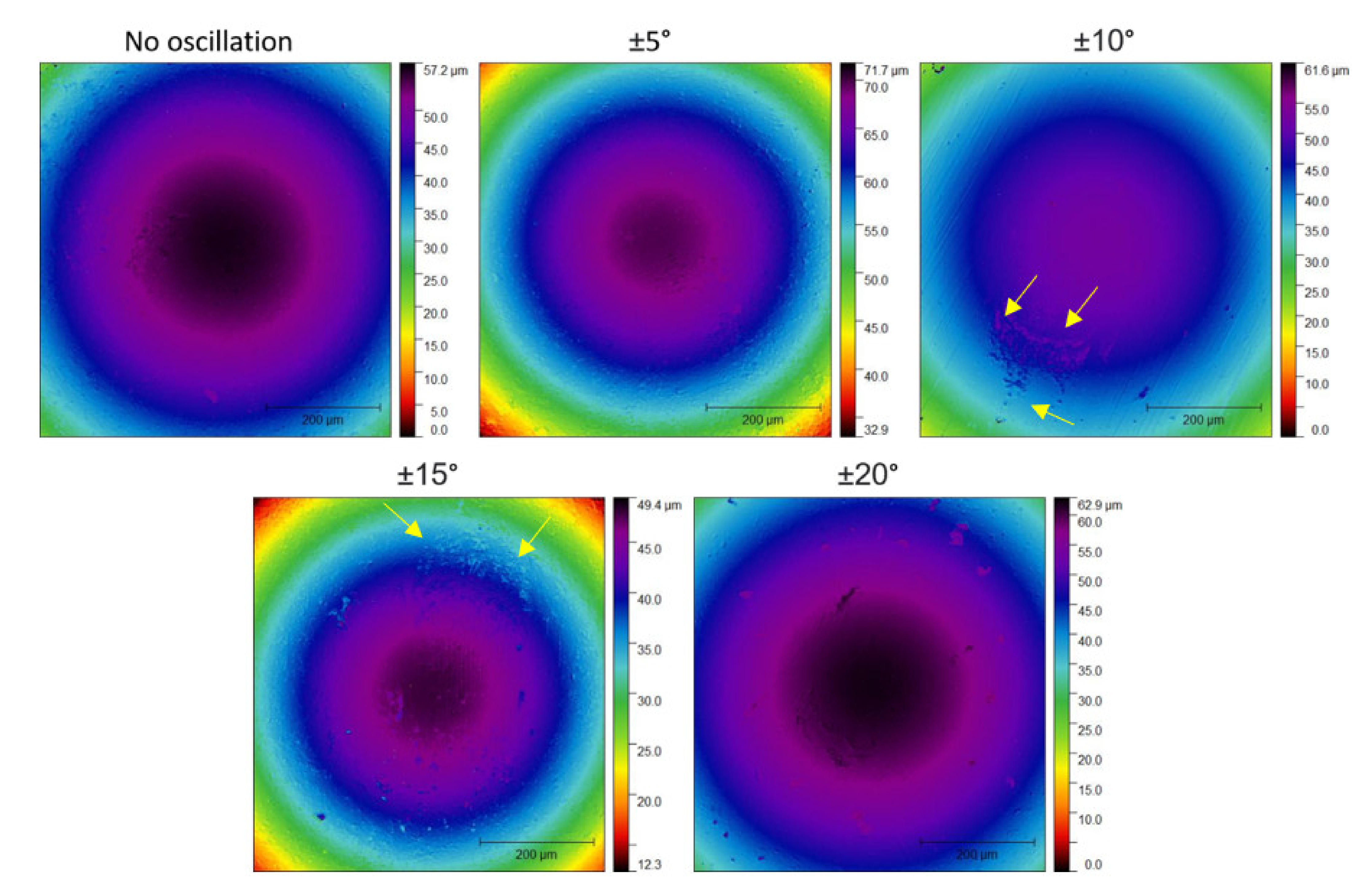
| Oscillatory Range | Ra | Rrms | Rsk |
|---|---|---|---|
| No oscillation | 20.98 | 26.55 | 0.27 |
| ±5 | 17.26 | 23.01 | 0.51 |
| ±10 | 14.76 | 20.74 | 1.23 |
| ±15 | 27.39 | 49.73 | 2.82 |
| ±20 | 26.62 | 33.36 | 0.11 |
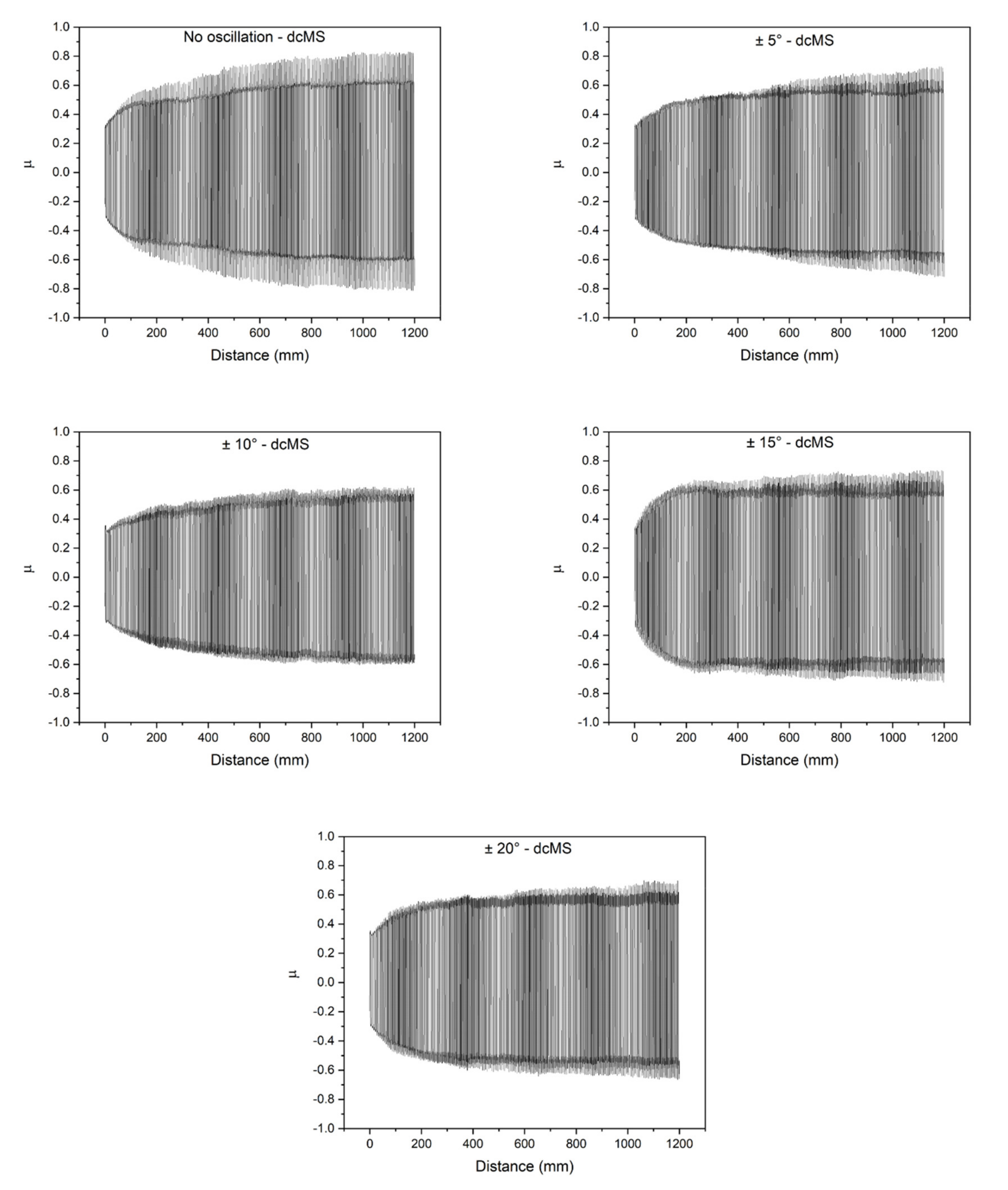
| Oscillatory Range | µrms | µmax | µmin |
|---|---|---|---|
| No oscillation | 0.572 | 0.831 | −0.813 |
| ±5 | 0.524 | 0.728 | −0.719 |
| ±10 | 0.495 | 0.626 | −0.604 |
| ±15 | 0.571 | 0.735 | −0.723 |
| ±20 | 0.519 | 0.698 | −0.665 |
Publisher’s Note: MDPI stays neutral with regard to jurisdictional claims in published maps and institutional affiliations. |
© 2021 by the authors. Licensee MDPI, Basel, Switzerland. This article is an open access article distributed under the terms and conditions of the Creative Commons Attribution (CC BY) license (https://creativecommons.org/licenses/by/4.0/).
Share and Cite
Avila, P.R.T.; Apolinário, R.C.; Rodrigues, A.M.; Fernandes, J.V.; Menezes, R.R.; Neves, G.d.A.; Pinto, H.C. On Improving Wear Resistance of Cr-Al-N Coatings Using Dynamic Glancing Angle DC Magnetron Sputtering. Nanomaterials 2021, 11, 2187. https://doi.org/10.3390/nano11092187
Avila PRT, Apolinário RC, Rodrigues AM, Fernandes JV, Menezes RR, Neves GdA, Pinto HC. On Improving Wear Resistance of Cr-Al-N Coatings Using Dynamic Glancing Angle DC Magnetron Sputtering. Nanomaterials. 2021; 11(9):2187. https://doi.org/10.3390/nano11092187
Chicago/Turabian StyleAvila, Pedro Renato Tavares, Raíra Chefer Apolinário, Alisson Mendes Rodrigues, Jucielle Veras Fernandes, Romualdo Rodrigues Menezes, Gelmires de Araújo Neves, and Haroldo Cavalcanti Pinto. 2021. "On Improving Wear Resistance of Cr-Al-N Coatings Using Dynamic Glancing Angle DC Magnetron Sputtering" Nanomaterials 11, no. 9: 2187. https://doi.org/10.3390/nano11092187
APA StyleAvila, P. R. T., Apolinário, R. C., Rodrigues, A. M., Fernandes, J. V., Menezes, R. R., Neves, G. d. A., & Pinto, H. C. (2021). On Improving Wear Resistance of Cr-Al-N Coatings Using Dynamic Glancing Angle DC Magnetron Sputtering. Nanomaterials, 11(9), 2187. https://doi.org/10.3390/nano11092187