
pH-Responsive Chitosan/Alginate Polyelectrolyte Complexes on Electrospun PLGA Nanofibers for Controlled Drug Release

 ,
,  , , ,
, , ,  , and
, and 
Abstract
:1. Introduction
2. Materials and Methods
3. Results
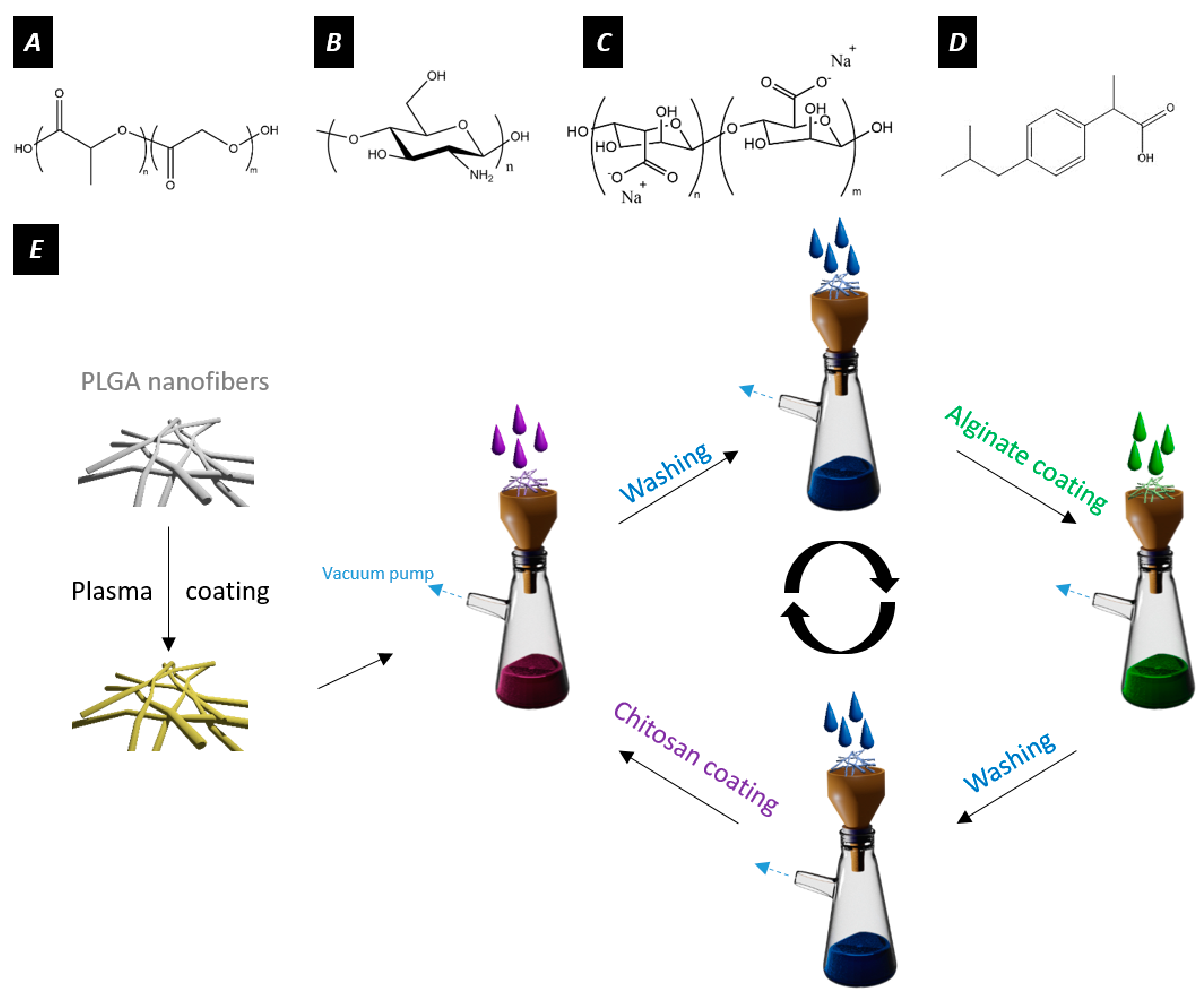
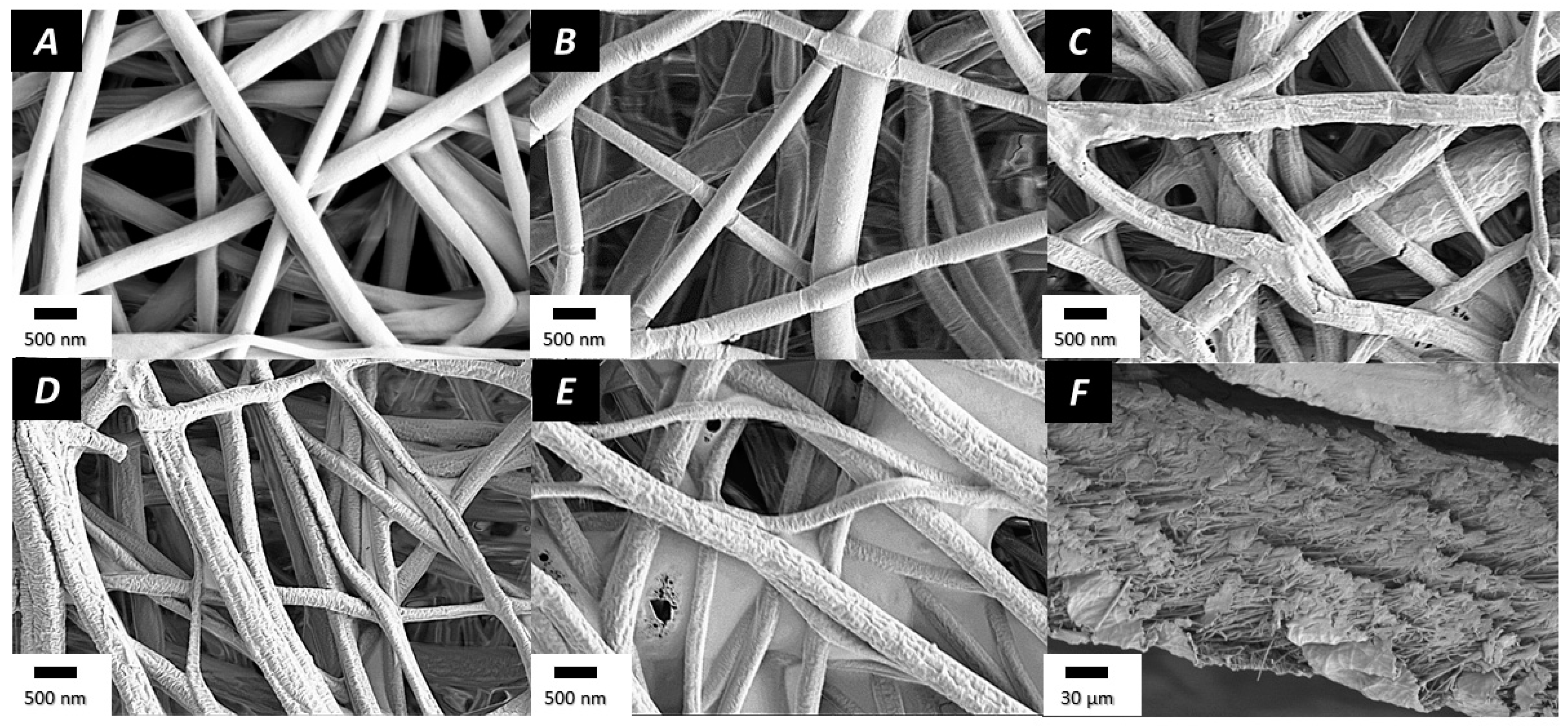
3.1. Preparation and Characterization of the Electrospun Nanofibers
3.1.1. Electrospinning
3.1.2. Plasma Coating and Layer-by-Layer Assembly
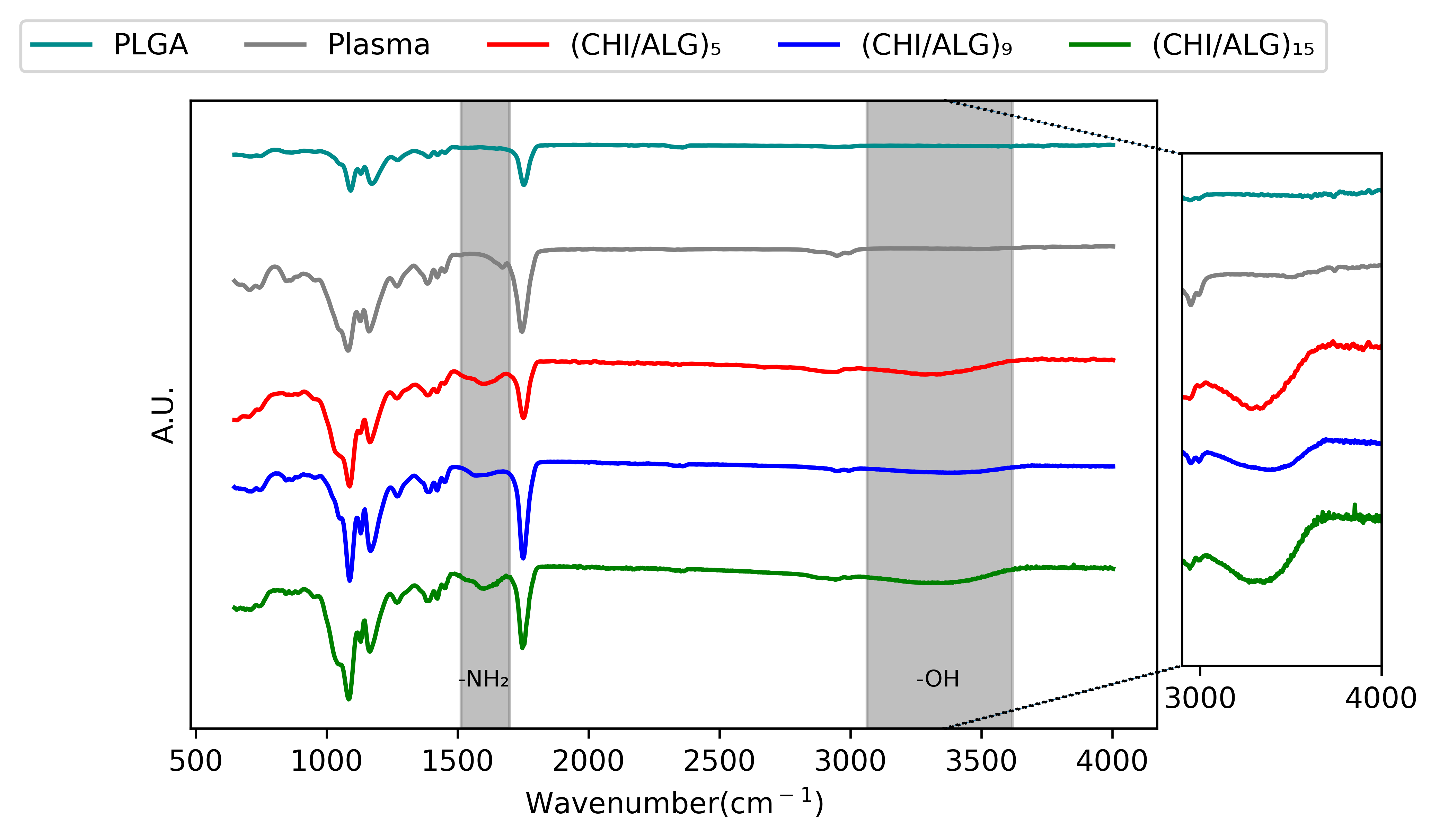
3.1.3. Fourier-Transform Infrared Spectroscopy
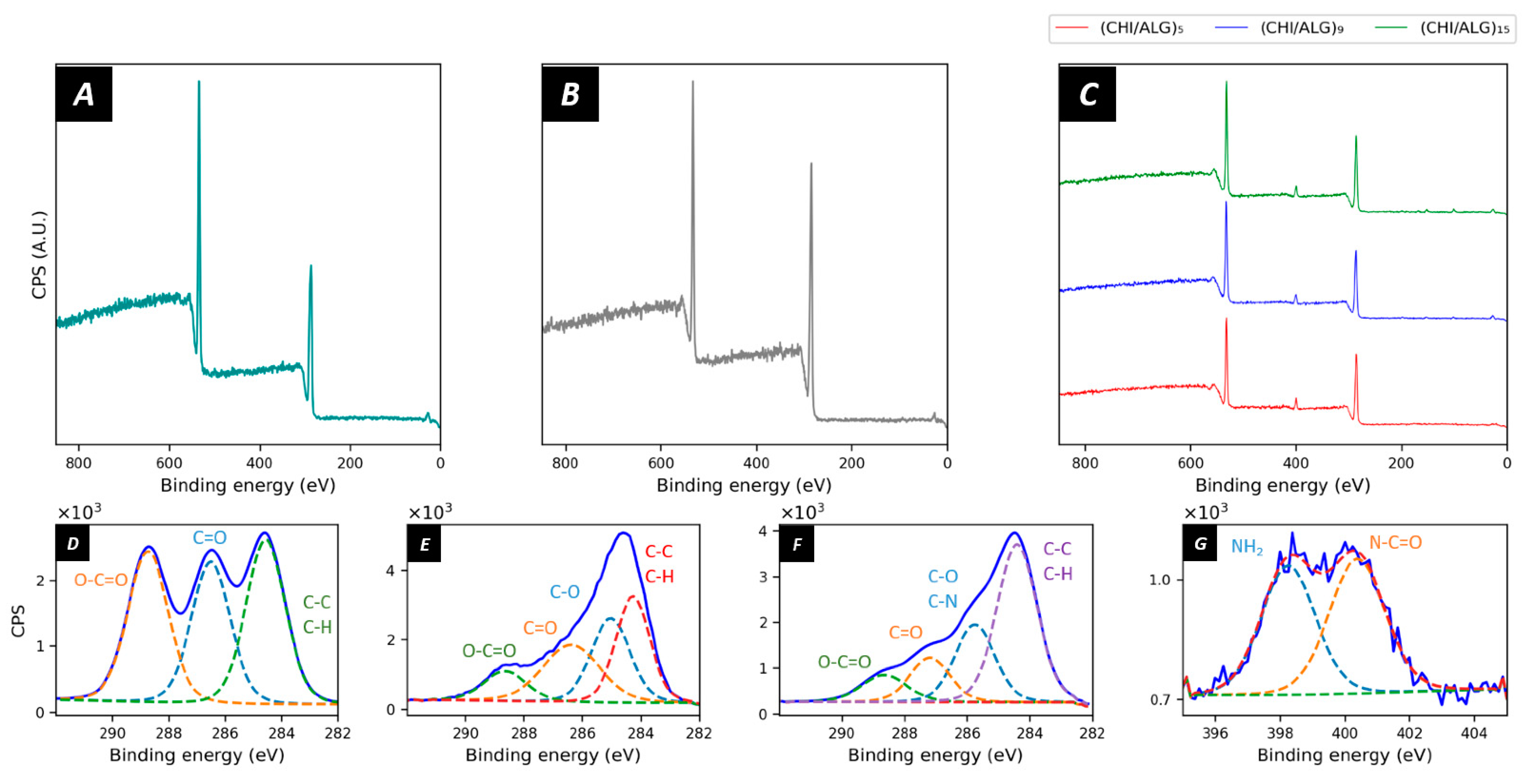
3.1.4. X-ray Photoelectron Spectroscopy (XPS)
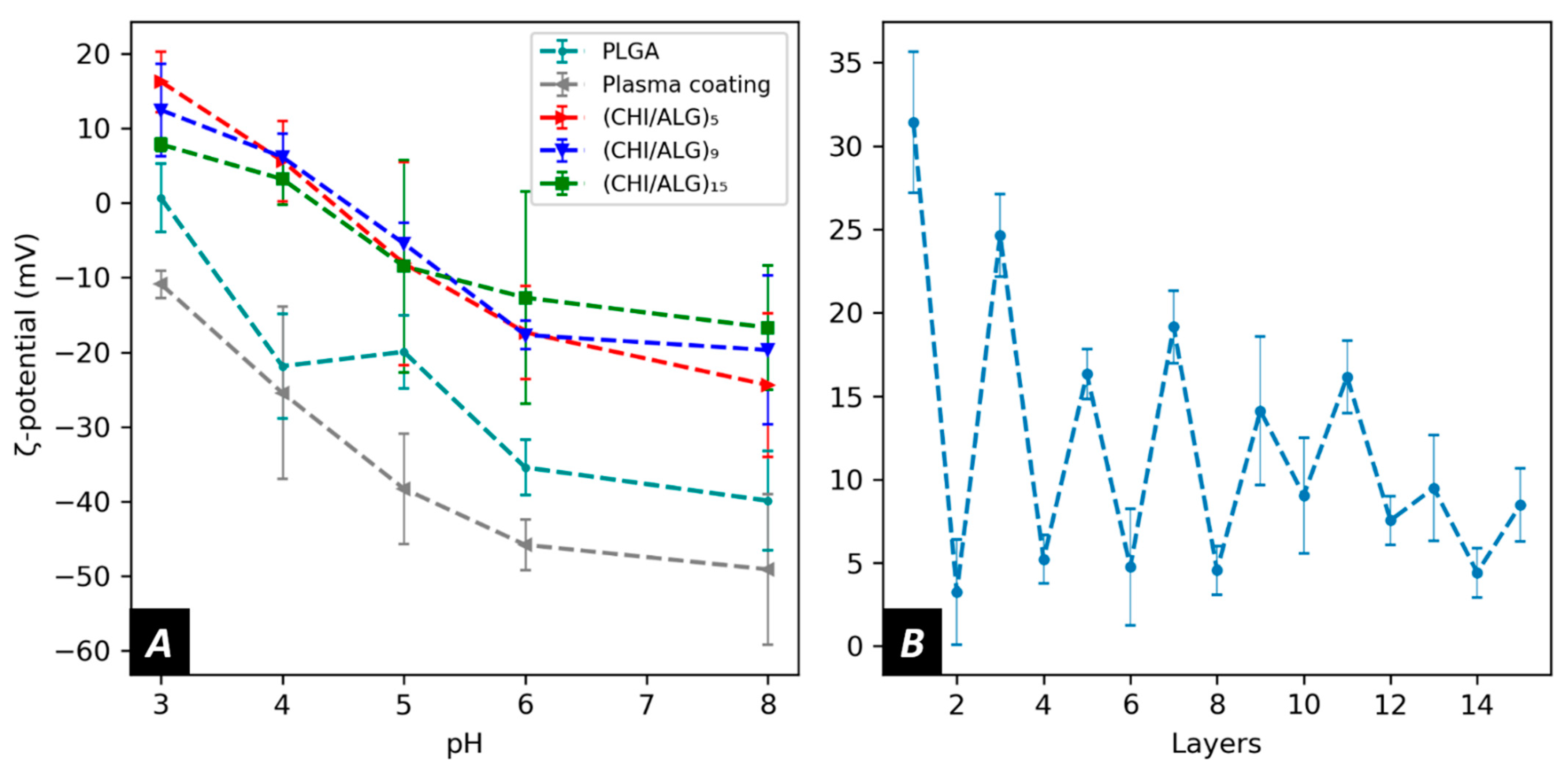
3.1.5. ζ-Potential Measurements
3.2. Drug Loading and Drug Release from the Chitosan/Alginates Modified Fibers
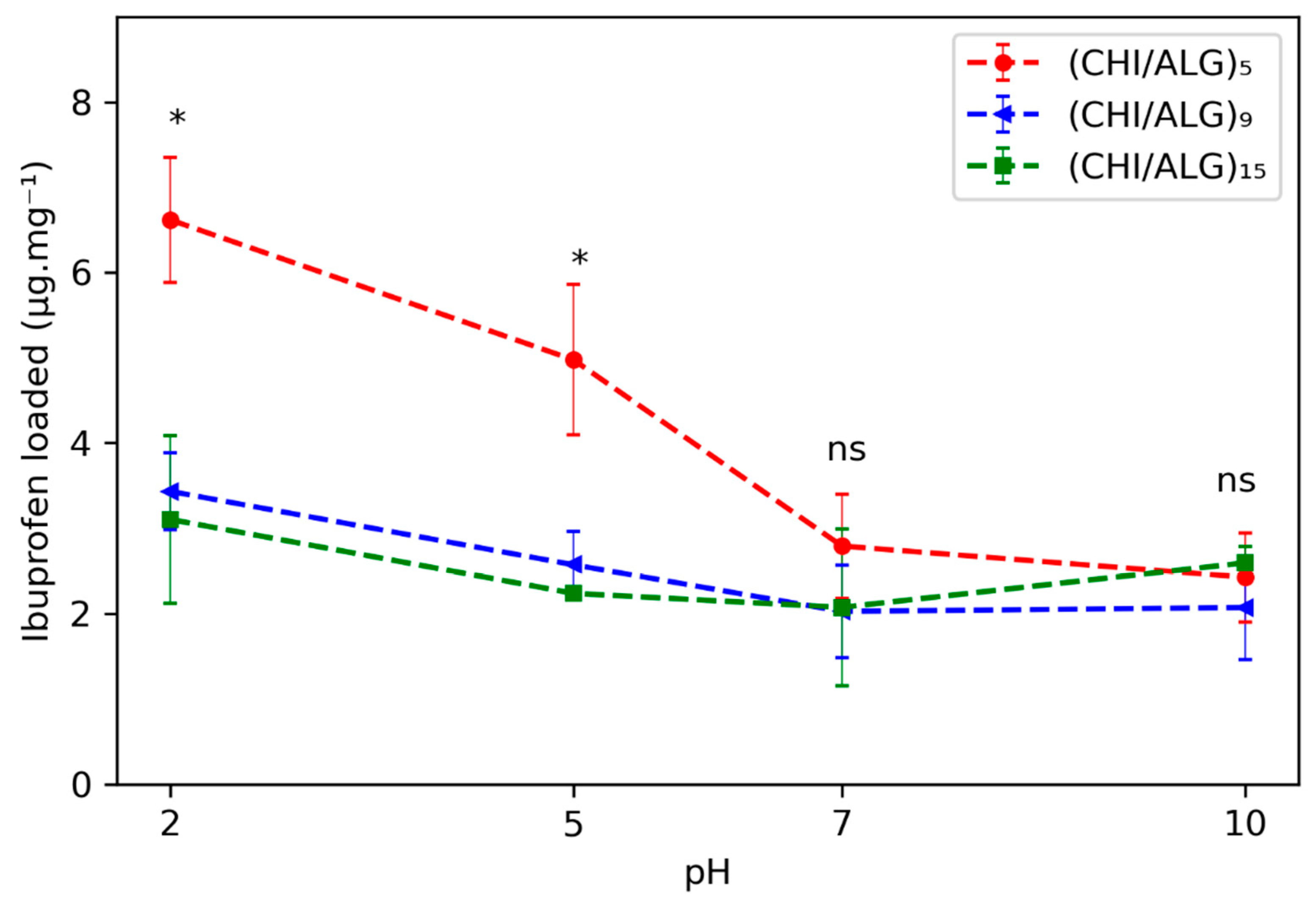
3.2.1. Drug Loading
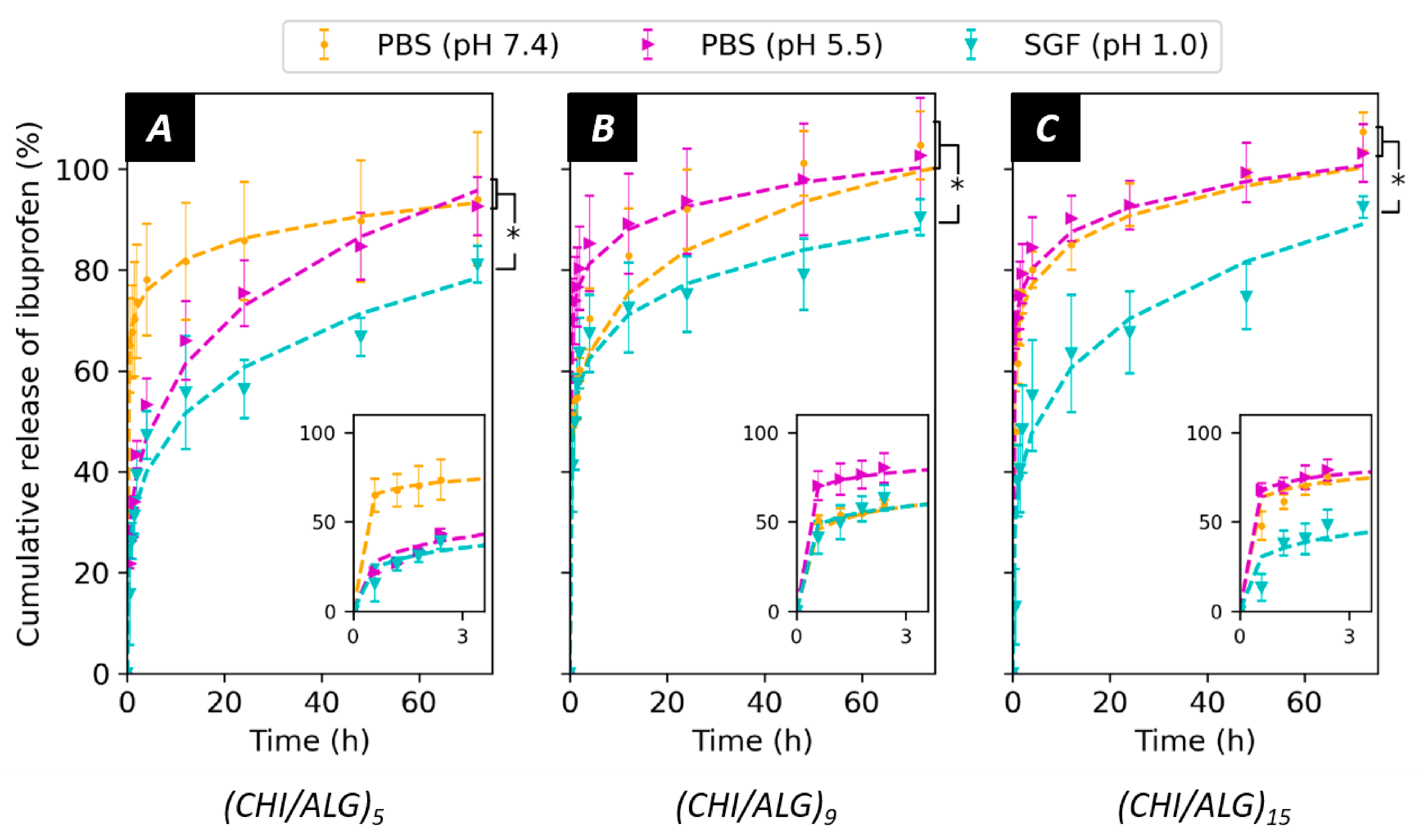
3.2.2. Drug Release
4. Discussion
5. Conclusions
Supplementary Materials
Author Contributions
Funding
Data Availability Statement
Acknowledgments
Conflicts of Interest
References
- Wang, Y.; Kotsuchibashi, Y.; Uto, K.; Ebara, M.; Aoyagi, T.; Liu, Y.; Narain, R. PH and Glucose Responsive Nanofibers for the Reversible Capture and Release of Lectins. Biomater. Sci. 2015, 3, 152–162. [Google Scholar] [CrossRef]
- Li, H.; Liu, K.; Williams, G.R.; Wu, J.; Wu, J.; Wang, H.; Niu, S.; Zhu, L.M. Dual Temperature and PH Responsive Nanofiber Formulations Prepared by Electrospinning. Colloids Surf. B Biointerfaces 2018, 171, 142–149. [Google Scholar] [CrossRef]
- Khatri, Z.; Ali, S.; Khatri, I.; Mayakrishnan, G.; Kim, S.H.; Kim, I.S. UV-Responsive Polyvinyl Alcohol Nanofibers Prepared by Electrospinning. Appl. Surf. Sci. 2015, 342, 64–68. [Google Scholar] [CrossRef]
- Meng, J.; Xiao, B.; Zhang, Y.; Liu, J.; Xue, H.; Lei, J.; Kong, H.; Huang, Y.; Jin, Z.; Gu, N.; et al. Super-Paramagnetic Responsive Nanofibrous Scaffolds under Static Magnetic Field Enhance Osteogenesis for Bone Repair in Vivo. Sci. Rep. 2013, 3, 2655. [Google Scholar] [CrossRef]
- Abrigo, M.; McArthur, S.L.; Kingshott, P. Electrospun Nanofibers as Dressings for Chronic Wound Care: Advances, Challenges, and Future Prospects. Macromol. Biosci. 2014, 14, 772–792. [Google Scholar] [CrossRef] [PubMed]
- Yuan, H.; Li, B.; Liang, K.; Lou, X.; Zhang, Y. Regulating Drug Release from PH- and Temperature-Responsive Electrospun CTS-g-PNIPAAm/Poly(Ethylene Oxide) Hydrogel Nanofibers. Biomed. Mater. 2014, 9, 055001. [Google Scholar] [CrossRef] [PubMed]
- Kim, Y.-J.; Ebara, M.; Aoyagi, T. Temperature-Responsive Electrospun Nanofibers for ‘on–off’ Switchable Release of Dextran. Sci. Technol. Adv. Mater. 2012, 13, 64203. [Google Scholar] [CrossRef]
- Ghavaminejad, A.; Sasikala, A.R.K.; Unnithan, A.R.; Thomas, R.G.; Jeong, Y.Y.; Vatankhah-Varnoosfaderani, M.; Stadler, F.J.; Park, C.H.; Kim, C.S. Mussel-Inspired Electrospun Smart Magnetic Nanofibers for Hyperthermic Chemotherapy. Adv. Funct. Mater. 2015, 25, 2867–2875. [Google Scholar] [CrossRef]
- Demirci, S.; Celebioglu, A.; Aytac, Z.; Uyar, T. PH-Responsive Nanofibers with Controlled Drug Release Properties. Polym. Chem. 2014, 5, 2050–2056. [Google Scholar] [CrossRef]
- González, E.; Frey, M.W. Synthesis, Characterization and Electrospinning of Poly(Vinyl Caprolactam-Co-Hydroxymethyl Acrylamide) to Create Stimuli-Responsive Nanofibers. Polymer 2017, 108, 154–162. [Google Scholar] [CrossRef]
- Chuah, C.; Wang, J.; Tavakoli, J.; Tang, Y. Novel Bacterial Cellulose-Poly (Acrylic Acid) Hybrid Hydrogels with Controllable Antimicrobial Ability as Dressings for Chronic Wounds. Polymers 2018, 10, 1323. [Google Scholar] [CrossRef] [PubMed]
- Watts, S.; Julian, T.R.; Maniura-Weber, K.; Graule, T.; Salentinig, S. Colloidal Transformations in MS2 Virus Particles: Driven by PH, Influenced by Natural Organic Matter. ACS Nano 2020, 14, 1879–1887. [Google Scholar] [CrossRef] [PubMed]
- Yuan, B.; Aziz, M.R.F.; Li, S.; Wu, J.; Li, D.; Li, R.-K. An Electro-Spun Tri-Component Polymer Biomaterial with Optoelectronic Properties for Neuronal Differentiation. Acta Biomater. 2021. [Google Scholar] [CrossRef] [PubMed]
- Boda, S.K.; Fischer, N.G.; Ye, Z.; Aparicio, C. Dual Oral Tissue Adhesive Nanofiber Membranes for PH-Responsive Delivery of Antimicrobial Peptides. Biomacromolecules 2020, 21, 4945–4961. [Google Scholar] [CrossRef]
- Weng, L.; Xie, J. Smart Electrospun Nanofibers for Controlled Drug Release: Recent Advances and New Perspectives. Curr. Pharm. Des. 2015, 21, 1944–1959. [Google Scholar] [CrossRef]
- Makadia, H.K.; Siegel, S.J. Poly Lactic-Co-Glycolic Acid (PLGA) as Biodegradable Controlled Drug Delivery Carrier. Polymers 2011, 3, 1377–1397. [Google Scholar] [CrossRef]
- Skaugrud, Ø.; Hagen, A.; Borgersen, B.; Dornish, M. Biomedical and Pharmaceutical Applications of Alginate and Chitosan. Biotechnol. Genet. Eng. Rev. 1999, 16, 23–40. [Google Scholar] [CrossRef]
- Chaturvedi, K.; Ganguly, K.; More, U.A.; Reddy, K.R.; Dugge, T.; Naik, B.; Aminabhavi, T.M.; Noolvi, M.N. Sodium alginate in drug delivery and biomedical areas. In Natural Polysaccharides in Drug Delivery and Biomedical Applications; Elsevier: Amsterdam, The Netherlands, 2019; pp. 59–100. ISBN 9780128170557. [Google Scholar]
- Qin, Y. Alginate Fibres: An Overview of the Production Processes and Applications in Wound Management. Polym. Int. 2008, 57, 171–180. [Google Scholar] [CrossRef]
- Ravi Kumar, M.N.V. A Review of Chitin and Chitosan Applications. React. Funct. Polym. 2000, 46, 1–27. [Google Scholar] [CrossRef]
- Gao, W.; Chan, J.M.; Farokhzad, O.C. PH-Responsive Nanoparticles for Drug Delivery. Mol. Pharm. 2010, 7, 1913–1920. [Google Scholar] [CrossRef] [PubMed]
- Zhang, Y.; Tao, L.; Li, S.; Wei, Y. Synthesis of Multiresponsive and Dynamic Chitosan-Based Hydrogels for Controlled Release of Bioactive Molecules. Biomacromolecules 2011, 12, 2894–2901. [Google Scholar] [CrossRef]
- Bhattarai, N.; Gunn, J.; Zhang, M. Chitosan-Based Hydrogels for Controlled, Localized Drug Delivery. Adv. Drug Deliv. Rev. 2010, 62, 83–99. [Google Scholar] [CrossRef] [PubMed]
- Prabaharan, M.; Mano, J.F. Stimuli-Responsive Hydrogels Based on Polysaccharides Incorporated with Thermo-Responsive Polymers as Novel Biomaterials. Macromol. Biosci. 2006, 6, 991–1008. [Google Scholar] [CrossRef]
- He, C.W.; Parowatkin, M.; Mailänder, V.; Flechtner-Mors, M.; Ziener, U.; Landfester, K.; Crespy, D. Sequence-Controlled Delivery of Peptides from Hierarchically Structured Nanomaterials. ACS Appl. Mater. Interfaces 2017, 9, 3885–3894. [Google Scholar] [CrossRef]
- Berger, J.; Reist, M.; Mayer, J.M.; Felt, O.; Gurny, R. Structure and Interactions in Chitosan Hydrogels Formed by Complexation or Aggregation for Biomedical Applications. Eur. J. Pharm. Biopharm. 2004, 57, 35–52. [Google Scholar] [CrossRef]
- Gierszewska, M.; Ostrowska-Czubenko, J.; Chrzanowska, E. PH-Responsive Chitosan/Alginate Polyelectrolyte Complex Membranes Reinforced by Tripolyphosphate. Eur. Polym. J. 2018, 101, 282–290. [Google Scholar] [CrossRef]
- Xie, J.; Michael, P.L.; Zhong, S.; Ma, B.; MacEwan, M.R.; Lim, C.T. Mussel Inspired Protein-Mediated Surface Modification to Electrospun Fibers and Their Potential Biomedical Applications. J. Biomed. Mater. Res. Part A 2012, 100 A, 929–938. [Google Scholar] [CrossRef]
- Lin, C.C.; Fu, S.J.; Lin, Y.C.; Yang, I.K.; Gu, Y. Chitosan-Coated Electrospun PLA Fibers for Rapid Mineralization of Calcium Phosphate. Int. J. Biol. Macromol. 2014, 68, 39–47. [Google Scholar] [CrossRef] [PubMed]
- Delcea, M.; Möhwald, H.; Skirtach, A.G. Stimuli-Responsive LbL Capsules and Nanoshells for Drug Delivery. Adv. Drug Deliv. Rev. 2011, 63, 730–747. [Google Scholar] [CrossRef]
- Wang, Y.; Ma, B.; Yin, A.; Zhang, B.; Luo, R.; Pan, J.; Wang, Y. Polycaprolactone Vascular Graft with Epigallocatechin Gallate Embedded Sandwiched Layer-by-Layer Functionalization for Enhanced Antithrombogenicity and Anti-Inflammation. J. Control. Release 2020, 320, 226–238. [Google Scholar] [CrossRef] [PubMed]
- Richardson, J.J.; Cui, J.; Björnmalm, M.; Braunger, J.A.; Ejima, H.; Caruso, F. Innovation in Layer-by-Layer Assembly. Chem. Rev. 2016, 116, 14828–14867. [Google Scholar] [CrossRef] [PubMed]
- Park, S.; Han, U.; Choi, D.; Hong, J. Layer-by-Layer Assembled Polymeric Thin Films as Prospective Drug Delivery Carriers: Design and Applications. Biomater. Res. 2018, 22, 29. [Google Scholar] [CrossRef] [PubMed]
- Zhang, X.; Liang, T.; Ma, Q. Layer-by-Layer assembled nano-drug delivery systems for cancer treatment. Drug Deliv. 2021, 28, 655–669. [Google Scholar] [CrossRef]
- Croisier, F.; Sibret, P.; Dupont-Gillain, C.C.; Genet, M.J.; Detrembleur, C.; Jérôme, C. Chitosan-Coated Electrospun Nanofibers with Antibacterial Activity. J. Mater. Chem. B 2015, 3, 3508–3517. [Google Scholar] [CrossRef]
- Deng, H.; Zhou, X.; Wang, X.; Zhang, C.; Ding, B.; Zhang, Q.; Du, Y. Layer-by-Layer Structured Polysaccharides Film-Coated Cellulose Nanofibrous Mats for Cell Culture. Carbohydr. Polym. 2010, 80, 474–479. [Google Scholar] [CrossRef]
- Fortunato, G.; Guex, A.G.; Popa, A.M.; Rossi, R.M.; Hufenus, R. Molecular Weight Driven Structure Formation of PEG Based E-Spun Polymer Blend Fibres. Polymer 2014, 55, 3139–3148. [Google Scholar] [CrossRef]
- Schneider, C.A.; Rasband, W.S.; Eliceiri, K.W. NIH Image to ImageJ: 25 Years of Image Analysis. Nat. Methods 2012, 9, 671–675. [Google Scholar] [CrossRef]
- Guex, A.G.; Kocher, F.M.; Fortunato, G.; Körner, E.; Hegemann, D.; Carrel, T.P.; Tevaearai, H.T.; Giraud, M.N. Fine-Tuning of Substrate Architecture and Surface Chemistry Promotes Muscle Tissue Development. Acta Biomater. 2012, 8, 1481–1489. [Google Scholar] [CrossRef]
- Körner, E.; Fortunato, G.; Hegemann, D. Influence of RF Plasma Reactor Setup on Carboxylated Hydrocarbon Coatings. Plasma Process. Polym. 2009, 6, 119–125. [Google Scholar] [CrossRef]
- Guex, A.G.; Hegemann, D.; Giraud, M.N.; Tevaearai, H.T.; Popa, A.M.; Rossi, R.M.; Fortunato, G. Covalent Immobilisation of VEGF on Plasma-Coated Electrospun Scaffolds for Tissue Engineering Applications. Colloids Surf. B Biointerfaces 2014, 123, 724–733. [Google Scholar] [CrossRef] [PubMed]
- Hegemann, D.; Indutnyi, I.; Zajíčková, L.; Makhneva, E.; Farka, Z.; Ushenin, Y.; Vandenbossche, M. Stable, Nanometer-Thick Oxygen-Containing Plasma Polymer Films Suited for Enhanced Biosensing. Plasma Process. Polym. 2018, 15, 1800090. [Google Scholar] [CrossRef]
- Peppas, N.A.; Narasimhan, B. Mathematical Models in Drug Delivery: How Modeling Has Shaped the Way We Design New Drug Delivery Systems. J. Control. Release 2014, 190, 75–81. [Google Scholar] [CrossRef]
- Ritger, P.L.; Peppas, N.A. A Simple Equation for Description of Solute Release I. Fickian and Non-Fickian Release from Non-Swellable Devices in the Form of Slabs, Spheres, Cylinders or Discs. J. Control. Release 1987, 5, 23–36. [Google Scholar] [CrossRef]
- Peppas, N. Chemical and Physical Structure of Polymers as Carriers for Controlled Release of Bioactive Agents: A Review. J. Macromol. Sci. Part C 1983, 23, 61–126. [Google Scholar] [CrossRef]
- R Core Team. R: A Language and Environment for Statistical Computing; R Core Team: Vienna, Austria, 2021. [Google Scholar]
- Vandenbossche, M.; Gunkel-Grabole, G.; Car, A.; Bernard, L.; Rupper, P.; Maniura-Weber, K.; Heuberger, M.; Faccio, G.; Hegemann, D. Near-Surface Structure of Plasma Polymer Films Affects Surface Behavior in Water and Its Interaction with Proteins. Plasma Chem. Plasma Process. 2018, 38, 851–870. [Google Scholar] [CrossRef]
- Chen, M.; Gao, S.; Dong, M.; Song, J.; Yang, C.; Howard, K.A.; Kjems, J.; Besenbacher, F. Chitosan/SiRNA Nanoparticles Encapsulated in PLGA Nanofibers for SiRNA Delivery. ACS Nano 2012, 6, 4835–4844. [Google Scholar] [CrossRef]
- Wang, Y.; Li, P.; Kong, L. Chitosan-Modified PLGA Nanoparticles with Versatile Surface for Improved Drug Delivery. AAPS PharmSciTech 2013, 14, 585–592. [Google Scholar] [CrossRef] [PubMed]
- Kwak, S.; Haider, A.; Gupta, K.C.; Kim, S.; Kang, I.K. Micro/Nano Multilayered Scaffolds of PLGA and Collagen by Alternately Electrospinning for Bone Tissue Engineering. Nanoscale Res. Lett. 2016, 11, 323. [Google Scholar] [CrossRef]
- Duan, B.; Yuan, X.; Zhu, Y.; Zhang, Y.; Li, X.; Zhang, Y.; Yao, K. A Nanofibrous Composite Membrane of PLGA-Chitosan/PVA Prepared by Electrospinning. Eur. Polym. J. 2006, 42, 2013–2022. [Google Scholar] [CrossRef]
- Meng, Z.X.; Wang, Y.S.; Ma, C.; Zheng, W.; Li, L.; Zheng, Y.F. Electrospinning of PLGA/Gelatin Randomly-Oriented and Aligned Nanofibers as Potential Scaffold in Tissue Engineering. Mater. Sci. Eng. C 2010, 30, 1204–1210. [Google Scholar] [CrossRef]
- You, Y.; Lee, S.J.; Min, B.M.; Park, W.H. Effect of Solution Properties on Nanofibrous Structure of Electrospun Poly(Lactic-Co-Glycolic Acid). J. Appl. Polym. Sci. 2006, 99, 1214–1221. [Google Scholar] [CrossRef]
- Xu, G.R.; Liu, X.Y.; Xu, J.M.; Li, L.; Su, H.C.; Zhao, H.L.; Feng, H.J. High Flux Nanofiltration Membranes Based on Layer-by-Layer Assembly Modified Electrospun Nanofibrous Substrate. Appl. Surf. Sci. 2018, 434, 573–581. [Google Scholar] [CrossRef]
- Mohamad, H.S.; Neuber, S.; Helm, C.A. Surface Forces of Asymmetrically Grown Polyelectrolyte Multilayers: Searching for the Charges. Langmuir 2019, 35, 15491–15499. [Google Scholar] [CrossRef] [PubMed]
- Tsume, Y.; Langguth, P.; Garcia-Arieta, A.; Amidon, G.L. In Silico Prediction of Drug Dissolution and Absorption with Variation in Intestinal PH for BCS Class II Weak Acid Drugs: Ibuprofen and Ketoprofen. Biopharm. Drug Dispos. 2012, 33, 366–377. [Google Scholar] [CrossRef]
- Piccirillo, G.; Carvajal Berrio, D.A.; Laurita, A.; Pepe, A.; Bochicchio, B.; Schenke-Layland, K.; Hinderer, S. Controlled and Tuneable Drug Release from Electrospun Fibers and a Non-Invasive Approach for Cytotoxicity Testing. Sci. Rep. 2019, 9, 1–10. [Google Scholar] [CrossRef] [PubMed]
- Baker, R.W.; Sanders, L.M. Controlled Release Delivery Systems. In Synthetic Membranes: Science, Engineering and Applications; Springer: Berlin, Germany, 1986; pp. 581–624. [Google Scholar]
- Mazaleuskaya, L.L.; Theken, K.N.; Gong, L.; Thorn, C.F.; Fitzgerald, G.A.; Altman, R.B.; Klein, T.E. PharmGKB Summary: Ibuprofen Pathways. Pharmacogenet. Genom. 2015, 25, 96–106. [Google Scholar] [CrossRef]
- Hua, S. Advances in Oral Drug Delivery for Regional Targeting in the Gastrointestinal Tract—Influence of Physiological, Pathophysiological and Pharmaceutical Factors. Front. Pharmacol. 2020, 11, 524. [Google Scholar] [CrossRef] [PubMed]
- Soscia, D.A.; Raof, N.A.; Xie, Y.; Cady, N.C.; Gadre, A.P. Antibiotic-Loaded PLGA Nanofibers for Wound Healing Applications. Adv. Eng. Mater. 2010, 12, B83–B88. [Google Scholar] [CrossRef]
- Hu, W.W.; Yu, H.N. Coelectrospinning of Chitosan/Alginate Fibers by Dual-Jet System for Modulating Material Surfaces. Carbohydr. Polym. 2013, 95, 716–727. [Google Scholar] [CrossRef]


Publisher’s Note: MDPI stays neutral with regard to jurisdictional claims in published maps and institutional affiliations. |
© 2021 by the authors. Licensee MDPI, Basel, Switzerland. This article is an open access article distributed under the terms and conditions of the Creative Commons Attribution (CC BY) license (https://creativecommons.org/licenses/by/4.0/).
Share and Cite
Schoeller, J.; Itel, F.; Wuertz-Kozak, K.; Gaiser, S.; Luisier, N.; Hegemann, D.; Ferguson, S.J.; Fortunato, G.; Rossi, R.M. pH-Responsive Chitosan/Alginate Polyelectrolyte Complexes on Electrospun PLGA Nanofibers for Controlled Drug Release. Nanomaterials 2021, 11, 1850. https://doi.org/10.3390/nano11071850
Schoeller J, Itel F, Wuertz-Kozak K, Gaiser S, Luisier N, Hegemann D, Ferguson SJ, Fortunato G, Rossi RM. pH-Responsive Chitosan/Alginate Polyelectrolyte Complexes on Electrospun PLGA Nanofibers for Controlled Drug Release. Nanomaterials. 2021; 11(7):1850. https://doi.org/10.3390/nano11071850
Chicago/Turabian StyleSchoeller, Jean, Fabian Itel, Karin Wuertz-Kozak, Sandra Gaiser, Nicolas Luisier, Dirk Hegemann, Stephen J. Ferguson, Giuseppino Fortunato, and René M. Rossi. 2021. "pH-Responsive Chitosan/Alginate Polyelectrolyte Complexes on Electrospun PLGA Nanofibers for Controlled Drug Release" Nanomaterials 11, no. 7: 1850. https://doi.org/10.3390/nano11071850
APA StyleSchoeller, J., Itel, F., Wuertz-Kozak, K., Gaiser, S., Luisier, N., Hegemann, D., Ferguson, S. J., Fortunato, G., & Rossi, R. M. (2021). pH-Responsive Chitosan/Alginate Polyelectrolyte Complexes on Electrospun PLGA Nanofibers for Controlled Drug Release. Nanomaterials, 11(7), 1850. https://doi.org/10.3390/nano11071850