Article

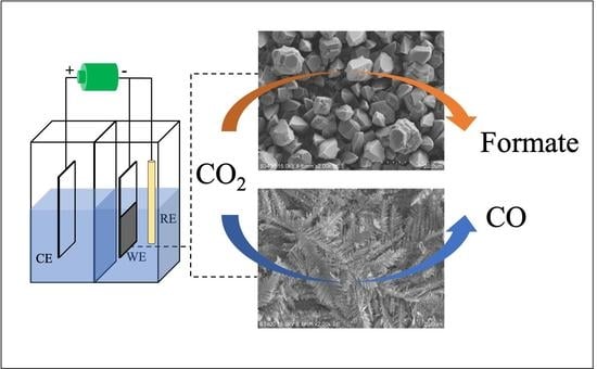
Effect of the Nanostructured Zn/Cu Electrocatalyst Morphology on the Electrochemical Reduction of CO2 to Value-Added Chemicals

by
Piriya Pinthong
1,
Phongsathon Klongklaew
1,
Piyasan Praserthdam
1 and
Joongjai Panpranot
1,2,*
1
Center of Excellence on Catalysis and Catalytic Reaction Engineering, Department of Chemical Engineering, Faculty of Engineering, Chulalongkorn University, Bangkok 10330, Thailand
2
Bio-Circular-Green-economy Technology & Engineering Center, BCGeTEC, Department of Chemical Engineering, Faculty of Engineering, Chulalongkorn University, Bangkok 10330, Thailand
*
Author to whom correspondence should be addressed.
Nanomaterials 2021, 11(7), 1671; https://doi.org/10.3390/nano11071671
Submission received: 24 May 2021 / Revised: 17 June 2021 / Accepted: 18 June 2021 / Published: 25 June 2021
(This article belongs to the Special Issue Metallic and Metal Oxide Nanoparticles and Their Applications)

Abstract

:
Zn/Cu electrocatalysts were synthesized by the electrodeposition method with various bath compositions and deposition times. X-ray diffraction results confirmed the presence of (101) and (002) lattice structures for all the deposited Zn nanoparticles. However, a bulky (hexagonal) structure with particle size in the range of 1–10 μm was obtained from a high-Zn-concentration bath, whereas a fern-like dendritic structure was produced using a low Zn concentration. A larger particle size of Zn dendrites could also be obtained when Cu2+ ions were added to the high-Zn-concentration bath. The catalysts were tested in the electrochemical reduction of CO2 (CO2RR) using an H-cell type reactor under ambient conditions. Despite the different sizes/shapes, the CO2RR products obtained on the nanostructured Zn catalysts depended largely on their morphologies. All the dendritic structures led to high CO production rates, while the bulky Zn structure produced formate as the major product, with limited amounts of gaseous CO and H2. The highest CO/H2 production rate ratio of 4.7 and a stable CO production rate of 3.55 μmol/min were obtained over the dendritic structure of the Zn/Cu–Na200 catalyst at −1.6 V vs. Ag/AgCl during 4 h CO2RR. The dissolution and re-deposition of Zn nanoparticles occurred but did not affect the activity and selectivity in the CO2RR of the electrodeposited Zn catalysts. The present results show the possibilities to enhance the activity and to control the selectivity of CO2RR products on nanostructured Zn catalysts.

Graphical Abstract

1. Introduction

Removal of CO2, the principal greenhouse gas, from the atmosphere is critical in order to avoid climate disasters caused by global warming. While CO2 capture and storage face geological risks such as leakage and earthquakes, the sequestration and use of CO2 as a carbon feedstock for chemicals, fuels, and other derivative materials are an alternative feasible and economic pathway to recycle CO2 into various useful resources [1]. Among the different CO2 conversion routes, electrochemical reduction of CO2 (CO2RR) using electricity from renewable energies is one of the best currently available technologies that can meet the energy demand for CO2 reduction by low-carbon and low-cost electricity. A variety of carbon-containing products, such as formate, carbon monoxide, methane, and alcohol, can be derived from CO2RR in aqueous electrolytes [1,2,3,4]. Carbon monoxide (CO) is an interesting product of this process because it can be used as a reactant for the Fischer–Tropsch process to produce hydrocarbon fuels and chemicals [5,6]. Furthermore, it can be simply separated from liquid electrolytes.
There are various kinds of electrocatalysts that promote CO production in the electrochemical reduction of CO2, including both noble metals such as Au and Ag [7,8,9] and non-noble metals such as Cu, Sn, and Zn [10,11,12,13]. Noble metals are expensive, limiting their uses in large-scale commercial applications; thus, non-noble metals are preferred. Typically, a metal foil or plate is used as a cathode (working electrode) in the electrochemical reduction of CO2, but this exhibits low efficiency and selectivity toward CO production [14,15,16]. Using catalysts with a high surface area is a promising way to improve catalytic activity. Nanostructured materials have been employed in several works, such as nanocoral silver [17] and nanoporous ZnO [18], due to the large surface area, and a CO Faradaic efficiency above 90% can be achieved. For Zn-based catalysts, the performance of CO2RR to CO has been reported to be improved using nanostructured Zn electrocatalysts prepared by the electrodeposition method. The electrodeposited Zn catalysts, however, possessed different structures, such as a dendritic structure [19], a hexagonal structure [20], or a foam structure [21]. However, it is quite difficult to make a fair comparison among these studies to determine which morphologies of the Zn nanostructure would provide the best performance. A number of research works have also paid attention to the development of bimetallic catalysts, because higher performances can be obtained by modifying the structure and morphology of the catalysts [22,23,24]. Gue et al. reported that a AgZn bimetallic thin film can promote the CO2RR to CO with a Faradaic efficiency of 84.2% [24] due to the synergistic effect of Zn and Ag. In addition, the Zn structure was further modified by mixing Cu and Zn [21]. Zn/Cu alloy catalysts exhibit higher CO selectivity than pure Cu or pure Zn [25].
In this work, Zn/Cu electrocatalysts were prepared by electrodeposition of Zn on Cu foil (Zn/Cu) and electrodeposition of Zn and Cu on Cu foil (ZnCu/Cu) in an electrodeposition solution consisting of NaCl (Zn/Cu-Na, ZnCu/Cu-Na) or HCl (Zn/Cu-H, ZnCu/Cu-H) with different deposition times. These catalysts were evaluated in the electrochemical reduction of CO2 to higher-value chemicals. The morphology, surface composition, and crystalline structure of these catalysts were investigated by scanning electron microscopy–energy dispersive X-ray spectroscopy (SEM-EDX) and X-ray diffraction (XRD).

2. Experimental Section

2.1. Electrode Preparation (Electrodeposition of Zn/Cu Electrodes)

Cu and Zn electrodes were prepared by cutting commercial Cu (0.1 mm thick, 99.9999%) and Zn (0.1 mm thick, 99.994%) foil, from Alfa Aesar® (Ward Hill, MA, USA), to a size of 10 × 25 mm2. The metal electrodes were physically polished with 800G sandpaper to remove the oxide surface and were then rinsed with deionized water before drying with nitrogen.
Nanostructured Zn/Cu and ZnCu/Cu electrodes with different morphologies were prepared by electrodeposition of ZnCl in either a NaCl or a HCl bath. A platinum rod (length 76 mm, diameter 2 mm) from Metrohm® (Herisau, Switzerland) was used as the counter electrode (anode). A polished Cu electrode was used as a cathode in a solution containing 0.05 M ZnCl2 (Ajax Finechem Pty Ltd., New south whales, Australia) and 0.05 M NaCl (Sigma-Aldrich, St. Louis, MO, USA). Electric current was applied at 20 mA/cm2 for 60 and 200 s to obtain Zn/Cu–Na60 and Zn/Cu–Na200, respectively. Furthermore, the effect of copper ions on the electrodeposition was investigated by adding CuCl2 to the solution. A solution consisting of 0.05 M ZnCl2, 0.05 M NaCl, and 1.5 mM CuCl2 was employed under similar electrodeposition conditions to obtain ZnCu/Cu–Na60 and ZnCu/Cu–Na200.
Under acidic conditions (HCl bath), electrodeposition was performed in a solution consisting of 0.2 M ZnCl2 and 1.5 M HCl. Electric current was applied at 0.3 A/cm2 for 60 and 200 s to obtain Zn/Cu–H60 and Zn/Cu–H200, respectively. The effect of Cu ions was also studied using a solution consisting of 0.2 M ZnCl2, 1.5 M HCl, and 6 mM CuCl2 to obtain ZnCu/Cu–H60 and ZnCu/Cu–H200. The obtained electrodes were rinsed with deionized water and dried with nitrogen.

2.2. Characterization of Electrodes

The crystalline structure of electrocatalyst samples was analyzed using a SIEMENS D 5000 X-ray diffractometer (Munich, Germany) with a CuKα radiation source (λ = 0.154439 nm) and nickel filtered in the 2θ degree range of 20°–80° (scan rate = 0.5 s/step). The morphology and surface composition of the electrocatalysts were analyzed by scanning electron microscopy–energy dispersive X-ray spectroscopy (SEM-EDX) using a Hitachi model S-3400N (Tokyo, Japan) scanning electron microscope.

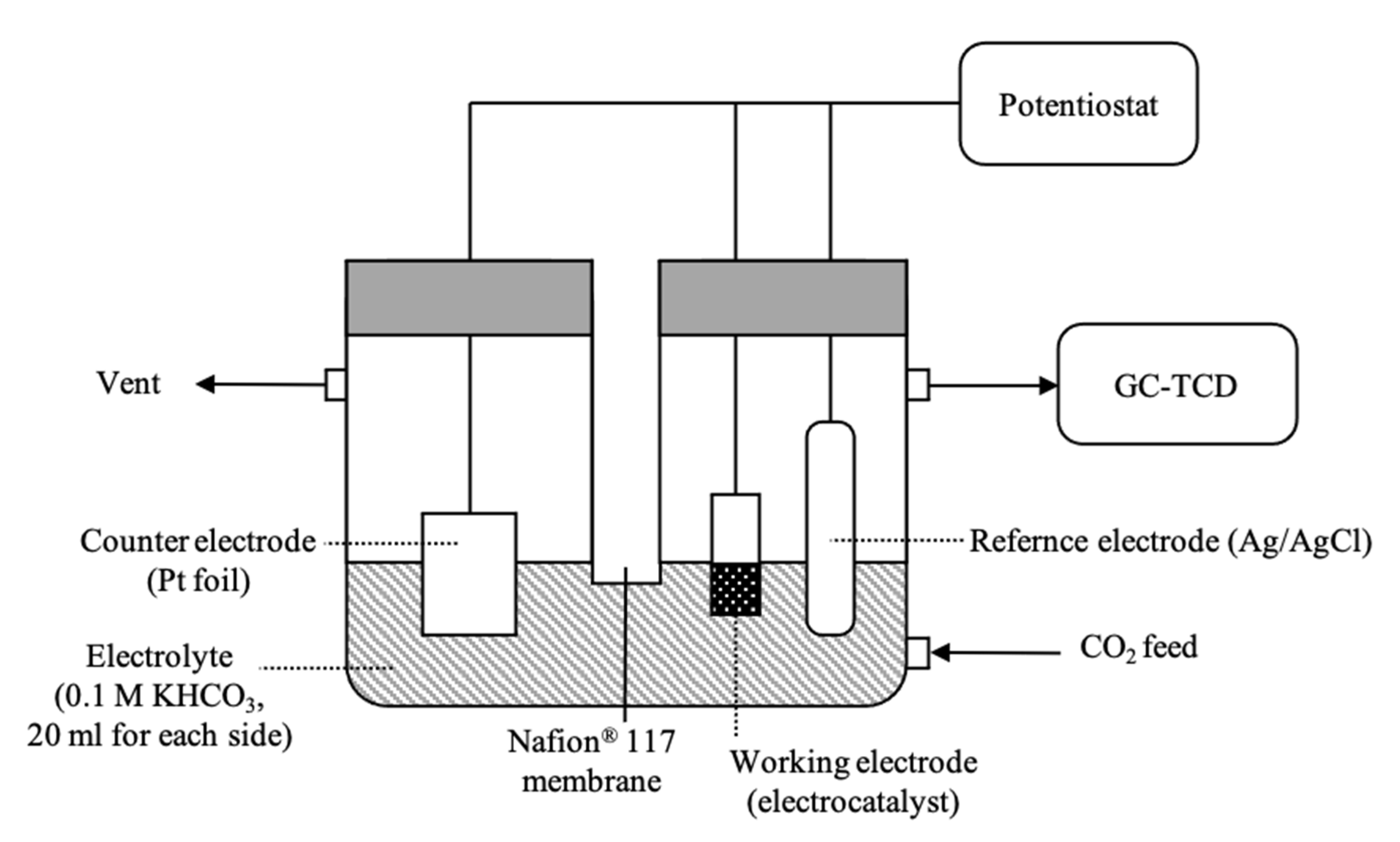
2.3. Electrochemical Reduction of CO2

All experiments on the electrochemical reduction of CO2 were performed in an H-type cell at room temperature and atmospheric pressure, as shown in the schematic diagram in Figure 1. The cathodic and anodic parts were separated by a Nafion® 117 membrane (Sigma-Aldrich, St. Louis, MO, USA). The experiments were carried out in a three-electrode cell system. A silver/silver chloride (Ag/AgCl) electrode from Metrohm® (Herisau, Switzerland) was used as the reference electrode. The counter electrode was a platinum foil (0.1 mm thick, 99.997%) from Alfa Aesar (Ward Hill, MA, USA). The working electrodes (Zn foil, Cu foil, and the electrodeposited electrodes) were immersed in an electrolyte solution with a geometrical area of 1 cm2. The catholyte and anolyte were 20 mL of 0.1 M KHCO3 solution. The electrolyte was saturated with 100 mL/min of CO2 gas for 30 min with a CO2 flow rate of 20 mL/min during the reaction. The reduction potential was controlled by a potentiostat during a reaction time of 70 min. The gaseous products were analyzed by an online gas chromatography system with a thermal conductivity detector (TCD). The liquid-phase products were identified and quantified using the NMR technique. The electrocatalysts with outstanding performances were further investigated at different reduction potentials from −1.4 to −2.0 V vs. Ag/AgCl, and a stability test was performed at the appropriate potential for 4 h.

3. Results and Discussion

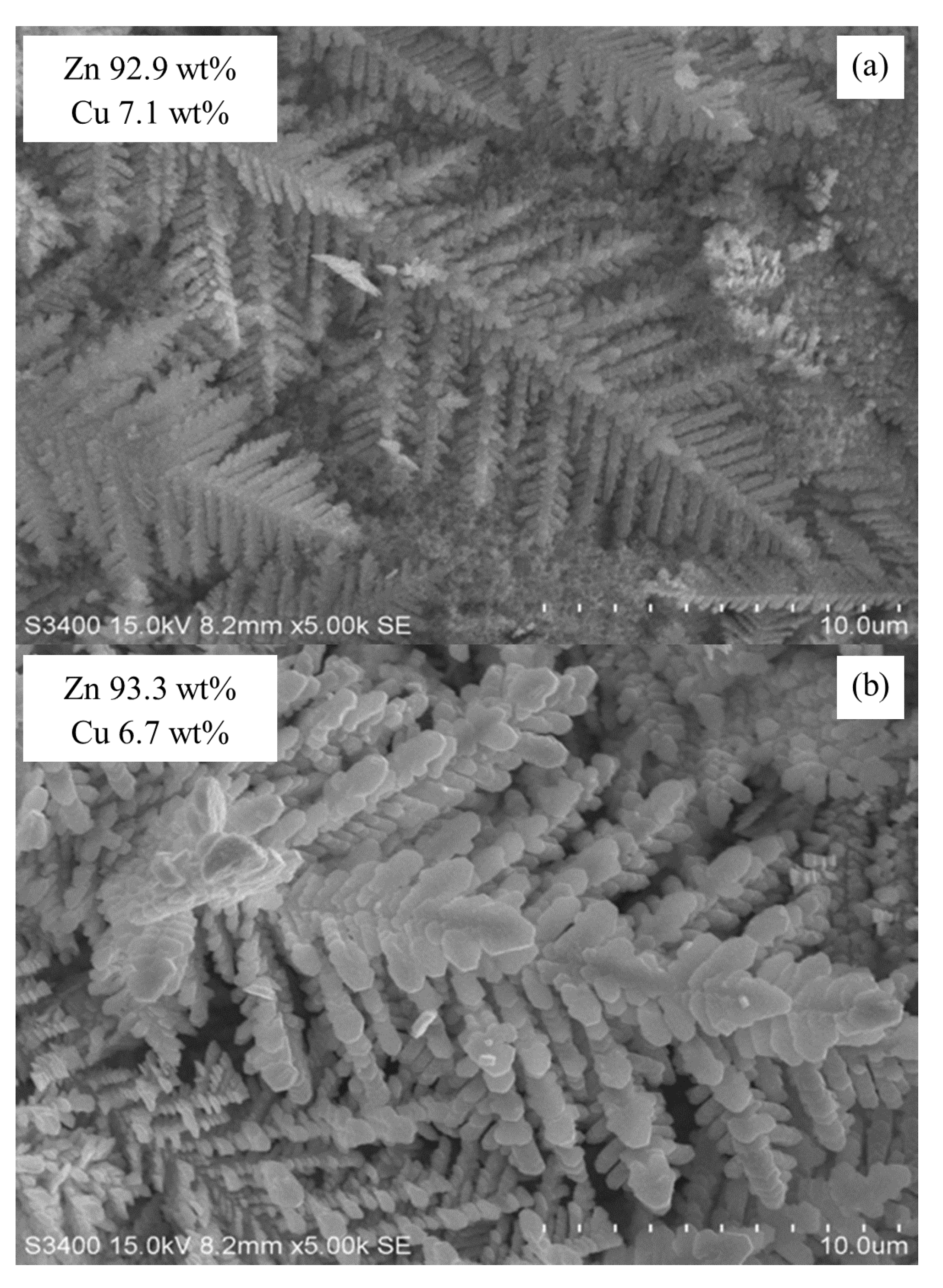
3.1. Electrocatalyst Characterization

The Zn/Cu and ZnCu/Cu electrocatalysts in this study were prepared by electrodeposition techniques under different conditions in order to obtain different morphologies of the deposited metal. The method allows successful deposition of 2D and 3D metal nanostructures on the substrates. Grain sizes of the deposited metals in the nanometer range were obtained by selecting electrodeposition variables (e.g., bath composition, pH, temperature, current density) such that nucleation of new grains was favored rather than growth of existing grains [26]. SEM images of the electrocatalyst samples are shown in Figure 2. A rock-like surface with some streaks was observed on the mechanically polished Zn and Cu foil (Figure 2a,b). After electrodeposition, a fern-like dendritic structure of Zn nanoparticles was obtained on Zn/Cu–Na60 and Zn/Cu–Na200, as shown in Figure 2c,d, respectively. The high deposition rate of Zn for 0.05 M ZnCl2 and the lower-concentration region of Zn ions at the electrocatalyst surface forced the dendritic structures to grow outward toward the higher-concentration region of Zn ions [19]. The deposition time (60 and 200 s) did not affect the morphology of Zn/Cu–Na, as the morphologies of Zn/Cu–Na60 and Zn/Cu–Na200 were similar. When Cu ions were added, the dendritic structures were not much altered, as seen in Figure 2e for ZnCu/Cu–Na60 and Figure 2f for ZnCu/Cu–Na200, probably due to the low concentration of CuCl2 (0.0015 M) in the deposition bath. In contrast, bulky (hexagonal) structures with average particle sizes of 1–4 and 4–10 μm were obtained on Zn/Cu–H60 and Zn/Cu–H200, respectively (Figure 2g,h). It is suggested that a bulky structure is formed because of the high ZnCl2 concentration (0.2 M) used in the deposition bath [19]. Increasing the deposition time resulted in an increased average particle size of Zn/Cu–H. Moreover, when Cu ions were simultaneously added to the HCl bath with Zn ions, another form of dendritic structure was observed, as shown in Figure 2i,j for ZnCu/Cu–H60 and ZnCu/Cu–H200, respectively. Although the deposition time did not have much impact on the dendritic morphology of ZnCu/Cu–H, adding Cu ions to the solution changed the morphology from a bulky structure to a dendritic structure as the concentration of Zn ions near the electrocatalyst surface was diluted by the presence of Cu ions. Cu ions can compete with Zn ions for deposition on a Cu foil. The deposited Cu can also accelerate the formation of hydrogen gas during the electrodeposition process. In addition, Cu has a higher hydrogen bond strength than Zn [21]. The hydrogen gas that is produced during the electrodeposition process also competes with Zn ions. It is also noticed that the particle size of the dendritic structure of ZnCu/Cu–H is bigger than that of ZnCu/Cu–Na due to the higher concentration of ZnCl2 in the deposition bath.
The surface compositions of the deposited electrodes are shown in Table 1. At a low Zn ion concentration in the NaCl bath, although increasing the deposition time did not affect the morphology of the fern-like dendritic structure being formed, the percentages of Zn increased from 75% to 93% as the deposition time increased from 60 to 200 s. Adding Cu did not have much impact on the amount of Zn being deposited under the conditions used (60 s, NaCl bath). Conversely, at a high Zn ion concentration in the HCl bath, there was little effect of the deposition time, whereas a lower amount of Zn was obtained when ZnCl2 and CuCl2 were simultaneously deposited.
The XRD results of all the electrocatalysts are shown in Figure 3. The XRD patterns of the deposited electrocatalysts matched perfectly with metallic Zn and Cu according to the JCPDS database (Cu: JCPDS 04-0836; Zn: JCPDS 00-004-0831). Except for the Zn foil, a strong characteristic peak corresponding to the Cu(200) facet was apparent at a 2θ degree of 50.1° [25]. The intensity of the Cu(200) peak decreased after deposition of Zn nanostructures on the Cu foil. The diffraction peaks at 36.3° and 43.3° (2θ) confirmed that Zn with a (101) and a (002) lattice structure was properly deposited on the surface of the Cu foil. The crystal planes (100) and (102) of Zn became more visible for Zn/Cu-–H200, in which the highest amount of Zn was deposited on the substrate. For the higher Zn concentration in the HCl bath, additional peaks corresponding to the Cu4Zn phase were detected on both ZnCu/Cu–H60 and ZnCu/Cu–H200 [21], indicating the formation of CuZn alloy by simultaneous deposition of Cu and Zn ions. Such result was not observed under low-Zn-concentration conditions (i.e., ZnCu/Cu–Na60 and ZnCu/Cu–Na200), and the addition of Cu2+ during electrodeposition neither changed the morphologies nor changed the structure of Zn being deposited.

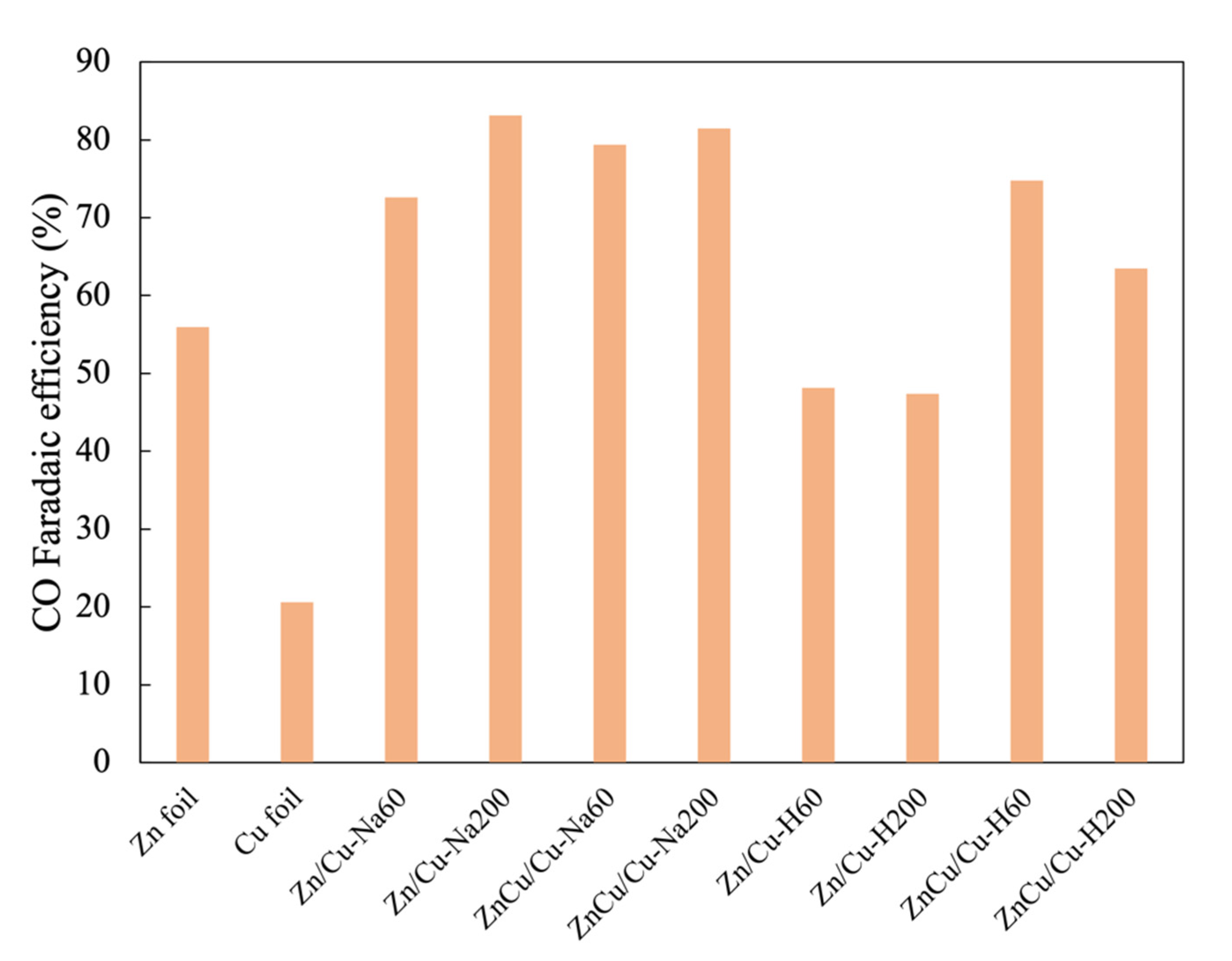
3.2. Electrocatalytic Performances in CO2RR

All the deposited electrodes were tested in the electrochemical reduction of CO2 at a potential of −1.6 V vs. Ag/AgCl for 70 min. The production rates for both gaseous and liquid products and CO Faradaic efficiency are shown in Table 2 and Figure 4, respectively. Both Zn foil and Cu foil can produce CO, formate, and n-propanol as the products from CO2RR, while H2 gas was produced by the hydrogen evolution reaction. Typically, a Cu foil exhibits higher activity than a Zn foil because its resistance is lower, resulting in a faster electron transfer rate [27]. Cu also has a lower theoretical limiting potential for formate production than Zn [28]. Furthermore, the higher binding energy of the Cu–CO bond leads to a higher production rate of n-propanol on a Cu foil than a Zn foil [29].
All the electrodeposited Zn catalysts with a dendritic structure (prepared under both low and high Zn ion concentrations) exhibited much higher CO production rates (~3–4.7 μmole/min) compared to the Zn foil (0.9 μmole/min) due to the higher surface area. Among them, the CO production rate increased with increasing Zn deposited. The CO/H2 production rate ratio ranged between 2.5 and 4.7, which was not much different from that of the Zn foil (4.1). It has been suggested that the dendritic structure contains a higher density of stepped sites that can suppress hydrogen evolution [19]. Among the various electrocatalysts, the highest CO/H2 production rate of 4.7 and a CO Faradaic efficiency of 83.2% were obtained on Zn/Cu–Na200 as it maintained the fern-like dendrite structure with a high amount of Zn. Furthermore, the CO Faradaic efficiency compared with previous works is shown in Table 3. The CO Faradaic efficiency of the dendritic Zn structure in this work was comparable to those reported in the literature and was relatively high comparing to the non-dendritic structure in a bicarbonate electrolyte. The results emphasize the effect of Zn morphology on the activity of Zn electrocatalysts. The CO:H2 ratio was relatively high compared to other Zn dendrite electrodes, as reported in the literature [19,30]. The production rates of formate (0.07–0.16 μmole/min) and n-propanol (0.02–0.06 μmole/min) over the Zn foil and the Zn dendrite electrocatalysts were essentially similar, despite the different conditions of the electrodeposition bath used. It should also be noted that the low coverage of Zn particles (as found in Zn/Cu–Na60 and ZnCu/Cu–Na60) and the presence of Cu4Zn alloy (as found in ZnCu/Cu–H60 and ZnCu/Cu–H200) did not have much influence on the selectivities of CO2RR products of the Zn-based electrocatalysts. Cu4Zn alloy can promote the formation of ethylene and ethanol, as reported by Ren et al. [27]. However, it was probably not the dominant phase in this study. Although the formation of other liquid hydrocarbon products such as methane and methanol has been reported on dendritic Zn [30], a Ag foam substrate with some certain crystalline structures and much higher over-potential is necessary in order to strongly bind CO* on the surface.
Unlike the dendritic structure Zn, the production rate of formate was drastically enhanced by more than five-fold on the electrodeposited Zn catalysts with bulky morphology, such as Zn/Cu–H60 and Zn/Cu–H200, compared to the Zn foil. However, there was little effect of the particle size of bulky Zn electrocatalysts (in the range of 1–10 μm) on the CO2RR activity and selectivity of the products. It is likely that the hexagonal close-pack structure of bulky Zn promotes formate production. According to a DFT study on various metals by Yoo et al., both COOH* (carboxyl) and HCOO* are presented as the intermediates of CO2RR, but the selective reduction of CO2 to formate (HCOOH) is more likely to occur via the HCOO* intermediate than the COOH* intermediate, which further reduces to CO and H2 [28]. The present results suggest that the pathway through HCOO* to formate is dominant on a bulky zinc structure, as depicted in the proposed scheme in Figure 5. Recently, cation vacancies (VZn) in the ZnS structure have been proposed to be new active sites on the ZnS surface that can stabilize HCOO* via O bridging between the intermediate and zinc ion vacancies VZn and hence is more efficient for the production of formate [31]. From these findings, it is speculated that the bulky zinc structure contains a high amount of cation vacancies, leading to the high production rate of formate, with limited formation of CO and H2. The absence of n-propanol on bulky Zn could be related to the high coverage of Zn species on the surface. As revealed by the EDX results, Zn/Cu–H60 and Zn/Cu–H200 showed the lowest percentages of Cu on the substrate (2–4 wt%). Typically, the formation of n-propanol occurs via C–C coupling of adsorbed-CO and adsorbed-methane intermediates on the Cu surface [32].
To further investigate the electrochemical behavior of the Zn/Cu–Na200 catalyst in CO2RR, linear sweep voltammetry (LSV) was performed. According to the LSV results in Figure 6, the Zn/Cu–Na200 catalyst was tested in CO2RR at different over-potentials of −1.4, −1.8, and −2.0 V vs. Ag/AgCl. The activity and selectivity of the Zn/Cu–Na200 catalyst are given in Table 4. At −1.4 V vs. Ag/AgCl, the CO formation rate was fairly low and surprisingly formate was not detected. Thermodynamically, the electron requirement for the half-cell reaction for n-propanol formation is 18 electrons, much higher than CO and formate production, which requires only 2 electrons [33]. The present results suggest that the production of formate may occur via a different pathway than the formation of CO and n-propanol on the Zn electrocatalysts. Increasing the over-potential from −1.4 to −1.6 resulted in a higher CO/H2 production rate, whereas a further increase in the potential beyond −1.6 V vs. Ag/AgCl led to lower CO/H2 production. Generally, the electron transfer rate at higher potential is faster, whereas the CO2 transfer rate remains unchanged. It has been suggested that this mass transfer limitation causes H2 formation [34]. The production rates of gaseous products monotonically increased as the over-potential increased from −1.4 to −2.0 V vs. Ag/AgCl, with only a slight increase in liquid products.
The stability test results of Zn/Cu–Na200 are shown in Figure 7. The formation rate of CO was comparatively stable around 3.55 μmol/min throughout the 4 h reaction time. The morphologies of the electrocatalysts before and after the stability test are shown in Figure 8. It is clearly evident that the particle size of the Zn dendrite increased from 0.2–0.5 to 0.5–1.2 μm, as shown in Figure 8a,b, respectively, indicating that dissolution and re-deposition of Zn nanoparticles occurs during CO2RR [19]. Nevertheless, the percentage of Zn remained the same at around 93 wt%. In addition, it was confirmed that the particle size or shape of the dendritic structure of Zn did not affect the activity and selectivity of the CO2RR of the electrodeposited Zn catalysts.

4. Conclusions

In this study, Zn/Cu and ZnCu/Cu electrocatalysts were prepared via the electrodeposition method with various bath compositions and deposition times. A low Zn concentration (e.g., 0.05 M ZnCl2 in NaCl solution or 0.2 M ZnCl2 in HCl solution in the presence of Cu2+) enabled mass transfer limited the growth of well-defined Zn dendrite structures. All the Zn dendrites exhibited higher activities in CO2RR than the Zn foil. The highest CO/H2 production rate (4.7) was obtained over Zn/Cu–Na200 having a fern-like dendritic structure and a relatively high amount of Zn being deposited. However, at the same over-potential, the activities and product selectivities of the Zn dendrites were essentially similar, regardless of the particle size/shape of the dendritic structure. On the contrary, the bulky Zn structure with an average particle size of 1–10 μm obtained from the high-Zn-concentration bath strongly favored the production of formate with limited amounts of gaseous CO and H2 products. The dissolution and re-deposition of Zn nanoparticles during the 4 h of reaction led to a larger particle size of the Zn dendritic structure but did not affect the activity and selectivity of the CO2RR of the electrodeposited Zn catalysts.

Author Contributions

Conceptualization, P.P. (Piriya Pinthong), P.K., and J.P.; formal analysis, P.P. (Piriya Pinthong) and P.K.; funding acquisition, J.P.; methodology, P.P. (Piriya Pinthong) and P.K.; project administration, J.P.; resources, P.P. (Piyasan Praserthdam); supervision, P.P. (Piyasan Praserthdam); validation, P.P. (Piyasan Praserthdam) and J.P.; writing—original draft, P.P. (Piriya Pinthong); writing—review and editing, J.P. All authors have read and agreed to the published version of the manuscript.

Funding

Financial support from the Rachadapisek Sompote Endowment Fund for the Postdoctoral Fellowship, Chulalongkorn University for P.P., the Research Team Promotional Grant from the National Research Council of Thailand (NRCT) for J.P., and the Malaysia-Thailand Joint Authority (MTJA) Research Cess Fund are gratefully acknowledged.

Conflicts of Interest

Piriya Pinthong, Phongsathon Klongklaew, Piyasan Praserthdam, and Joongjai Panpranot declare that they have no conflict of interest.

References

  1. Choi, J.; Kim, M.J.; Ahn, S.H.; Choi, I.; Jang, J.H.; Ham, Y.S.; Kim, J.J.; Kim, S.-K. Electrochemical CO2 reduction to CO on dendritic Ag–Cu electrocatalysts prepared by electrodeposition. Chem. Eng. J. 2016, 299, 37–44. [Google Scholar] [CrossRef]
  2. Krause, R.; Reinisch, D.; Reller, C.; Eckert, H.; Hartmann, D.; Taroata, D.; Wiesner-Fleischer, K.; Bulan, A.; Lueken, A.; Schmid, G. Industrial application aspects of the electrochemical reduction of CO2 to CO in aqueous electrolyte. Chem. Ing. Tech. 2020, 92, 53–61. [Google Scholar] [CrossRef]
  3. Abdinejad, M.; Dao, C.; Deng, B.; Dinic, F.; Voznyy, O.; Zhang, X.-A.; Kraatz, H.-B. Electrocatalytic reduction of CO2 to CH4 and CO in aqueous solution using pyridine-porphyrins immobilized onto carbon nanotubes. ACS Sustain. Chem. Eng. 2020, 8, 9549–9557. [Google Scholar] [CrossRef]
  4. de Brito, J.F.; Irikura, K.; Terzi, C.M.; Nakagaki, S.; Zanoni, M.V.B. The great performance of TiO2 nanotubes electrodes modified by copper (II) porphyrin in the reduction of carbon dioxide to alcohol. J. CO2 Util. 2020, 41, 101261. [Google Scholar] [CrossRef]
  5. Weststrate, C.; Van De Loosdrecht, J.; Niemantsverdriet, J. Spectroscopic insights into cobalt-catalyzed Fischer-Tropsch synthesis: A review of the carbon monoxide interaction with single crystalline surfaces of cobalt. J. Catal. 2016, 342, 1–16. [Google Scholar] [CrossRef]
  6. Khodakov, A.Y.; Chu, W.; Fongarland, P. Advances in the development of novel cobalt Fischer−Tropsch catalysts for synthesis of long-chain hydrocarbons and clean fuels. Chem. Rev. 2007, 107, 1692–1744. [Google Scholar] [CrossRef] [PubMed]
  7. Hori, Y. Electrochemical CO2 Reduction on Metal Electrodes. In Modern Aspects of Electrochemistry; Vayenas, C.G., White, R.E., Gamboa-Aldeco, M.E., Eds.; Springer: New York, NY, USA, 2008; pp. 89–189. [Google Scholar]
  8. Guo, W.; Shim, K.; Ngome, F.O.O.; Moon, Y.H.; Choi, S.-Y.; Kim, Y.-T. Highly active coral-like porous silver for electrochemical reduction of CO2 to CO. J. CO2 Util. 2020, 41, 101242. [Google Scholar] [CrossRef]
  9. Sarno, M.; Ponticorvo, E.; Piotto, S.; Nardiello, A.M.; De Pasquale, S.; Funicello, N. AuAg/ZnO nanocatalyst for CO2 valorization and H2 and CO electrochemical production. J. CO2 Util. 2020, 39, 101179. [Google Scholar] [CrossRef]
  10. Nguyen, D.L.T.; Jee, M.S.; Won, D.H.; Jung, H.; Oh, H.-S.; Min, B.K.; Hwang, Y.J. Selective CO2 Reduction on Zinc Electrocatalyst: The Effect of Zinc Oxidation State Induced by Pretreatment Environment. ACS Sustain. Chem. Eng. 2017, 5, 11377–11386. [Google Scholar] [CrossRef]
  11. Jiang, K.; Huang, Y.; Zeng, G.; Toma, F.M.; Goddard, W.A., III; Bell, A.T. Effects of surface roughness on the electrochemical reduction of CO2 over Cu. ACS Energy Lett. 2020, 5, 1206–1214. [Google Scholar] [CrossRef] [Green Version]
  12. Cheng, F.; Zhang, X.; Mu, K.; Ma, X.; Jiao, M.; Wang, Z.; Limpachanangkul, P.; Chalermsinsuwan, B.; Gao, Y.; Li, Y. Recent Progress of Sn-Based Derivative Catalysts for Electrochemical Reduction of CO2. Energy Technol. 2021, 9, 2000799. [Google Scholar] [CrossRef]
  13. Xiao, J.; Gao, M.-R.; Liu, S.; Luo, J.-L. Hexagonal Zn nanoplates enclosed by Zn (100) and Zn (002) facets for highly selective CO2 electroreduction to CO. ACS Appl. Mater. Interfaces 2020, 12, 31431–31438. [Google Scholar] [CrossRef]
  14. Quan, F.; Zhong, D.; Song, H.; Jia, F.; Zhang, L. A highly efficient zinc catalyst for selective electroreduction of carbon dioxide in aqueous NaCl solution. J. Mater. Chem. A 2015, 3, 16409–16413. [Google Scholar] [CrossRef]
  15. Wu, J.; Risalvato, F.G.; Ke, F.-S.; Pellechia, P.; Zhou, X.-D. Electrochemical reduction of carbon dioxide I. Effects of the electrolyte on the selectivity and activity with Sn electrode. J. Electrochem. Soc. 2012, 159, F353. [Google Scholar] [CrossRef]
  16. Lv, W.; Zhang, R.; Gao, P.; Lei, L. Studies on the faradaic efficiency for electrochemical reduction of carbon dioxide to formate on tin electrode. J. Power Sources 2014, 253, 276–281. [Google Scholar] [CrossRef]
  17. Hsieh, Y.-C.; Senanayake, S.D.; Zhang, Y.; Xu, W.; Polyansky, D.E. Effect of chloride anions on the synthesis and enhanced catalytic activity of silver nanocoral electrodes for CO2 electroreduction. ACS Catal. 2015, 5, 5349–5356. [Google Scholar] [CrossRef]
  18. Jiang, X.; Cai, F.; Gao, D.; Dong, J.; Miao, S.; Wang, G.; Bao, X. Electrocatalytic reduction of carbon dioxide over reduced nanoporous zinc oxide. Electrochem. Commun. 2016, 68, 67–70. [Google Scholar] [CrossRef]
  19. Rosen, J.; Hutchings, G.S.; Lu, Q.; Forest, R.V.; Moore, A.; Jiao, F. Electrodeposited Zn Dendrites with Enhanced CO Selectivity for Electrocatalytic CO2 Reduction. ACS Catal. 2015, 5, 4586–4591. [Google Scholar] [CrossRef]
  20. Won da, H.; Shin, H.; Koh, J.; Chung, J.; Lee, H.S.; Kim, H.; Woo, S.I. Highly Efficient, Selective, and Stable CO2 Electroreduction on a Hexagonal Zn Catalyst. Angew. Chem. Int. Ed. Engl. 2016, 55, 9297–9300. [Google Scholar] [CrossRef] [PubMed]
  21. Moreno-Garcia, P.; Schlegel, N.; Zanetti, A.; Cedeno Lopez, A.; Galvez-Vazquez, M.J.; Dutta, A.; Rahaman, M.; Broekmann, P. Selective Electrochemical Reduction of CO2 to CO on Zn-Based Foams Produced by Cu(2+) and Template-Assisted Electrodeposition. ACS Appl. Mater. Interfaces 2018, 10, 31355–31365. [Google Scholar] [CrossRef]
  22. Zhu, S.; Wang, Q.; Qin, X.; Gu, M.; Tao, R.; Lee, B.P.; Zhang, L.; Yao, Y.; Li, T.; Shao, M. Tuning structural and compositional effects in Pd–Au nanowires for highly selective and active CO2 electrochemical reduction reaction. Adv. Energy Mater. 2018, 8, 1802238. [Google Scholar] [CrossRef]
  23. Kim, J.-H.; Woo, H.; Yun, S.-W.; Jung, H.-W.; Back, S.; Jung, Y.; Kim, Y.-T. Highly active and selective Au thin layer on Cu polycrystalline surface prepared by galvanic displacement for the electrochemical reduction of CO2 to CO. Appl. Catal. B Environ. 2017, 213, 211–215. [Google Scholar] [CrossRef]
  24. Guo, W.; Shim, K.; Kim, Y.-T. Ag layer deposited on Zn by physical vapor deposition with enhanced CO selectivity for electrochemical CO2 reduction. Appl. Surf. Sci. 2020, 526, 146651. [Google Scholar] [CrossRef]
  25. Keerthiga, G.; Chetty, R. Electrochemical Reduction of Carbon Dioxide on Zinc-Modified Copper Electrodes. J. Electrochem. Soc. 2017, 164, H164–H169. [Google Scholar] [CrossRef]
  26. Clark, D.; Wood, D.; Erb, U. Industrial applications of electrodeposited nanocrystals. Nanostruct. Mater. 1997, 9, 755–758. [Google Scholar] [CrossRef]
  27. Ren, D.; Ang, B.S.-H.; Yeo, B.S. Tuning the selectivity of carbon dioxide electroreduction toward ethanol on oxide-derived Cu x Zn catalysts. ACS Catal. 2016, 6, 8239–8247. [Google Scholar] [CrossRef]
  28. Yoo, J.S.; Christensen, R.; Vegge, T.; Norskov, J.K.; Studt, F. Theoretical Insight into the Trends that Guide the Electrochemical Reduction of Carbon Dioxide to Formic Acid. ChemSusChem 2016, 9, 358–363. [Google Scholar] [CrossRef] [PubMed]
  29. Kuhl, K.P.; Hatsukade, T.; Cave, E.R.; Abram, D.N.; Kibsgaard, J.; Jaramillo, T.F. Electrocatalytic conversion of carbon dioxide to methane and methanol on transition metal surfaces. J. Am. Chem. Soc. 2014, 136, 14107–14113. [Google Scholar] [CrossRef] [PubMed]
  30. Low, Q.H.; Loo, N.W.X.; Calle-Vallejo, F.; Yeo, B.S. Enhanced Electroreduction of Carbon Dioxide to Methanol Using Zinc Dendrites Pulse-Deposited on Silver Foam. Angew. Chem. Int. Ed. 2019, 58, 2256–2260. [Google Scholar] [CrossRef] [PubMed]
  31. Pang, H.; Meng, X.; Li, P.; Chang, K.; Zhou, W.; Wang, X.; Zhang, X.; Jevasuwan, W.; Fukata, N.; Wang, D. Cation vacancy-initiated CO2 photoreduction over ZnS for efficient formate production. ACS Energy Lett. 2019, 4, 1387–1393. [Google Scholar] [CrossRef]
  32. Ren, D.; Wong, N.T.; Handoko, A.D.; Huang, Y.; Yeo, B.S. Mechanistic Insights into the Enhanced Activity and Stability of Agglomerated Cu Nanocrystals for the Electrochemical Reduction of Carbon Dioxide to n-Propanol. J. Phys. Chem. Lett. 2016, 7, 20–24. [Google Scholar] [CrossRef] [PubMed]
  33. Kuhl, K.P.; Cave, E.R.; Abram, D.N.; Jaramillo, T.F. New insights into the electrochemical reduction of carbon dioxide on metallic copper surfaces. Energy Environ. Sci. 2012, 5, 7050–7059. [Google Scholar] [CrossRef]
  34. Hatsukade, T.; Kuhl, K.P.; Cave, E.R.; Abram, D.N.; Jaramillo, T.F. Insights into the electrocatalytic reduction of CO2 on metallic silver surfaces. Phys. Chem. Chem. Phys. 2014, 16, 13814–13819. [Google Scholar] [CrossRef] [PubMed]
Figure 1. Schematic electrochemical CO2 reduction setup.
Nanomaterials 11 01671 g001
Figure 2. SEM images of (a) Zn foil, (b) Cu foil, (c) Zn/Cu–Na60, (d) Zn/Cu–Na200, (e) ZnCu/Cu–Na60, (f) ZnCu/Cu–Na200, (g) Zn/Cu–H60, (h) Zn/Cu–H200, (i) ZnCu/Cu–H60, and (j) ZnCu/Cu–H200.
Nanomaterials 11 01671 g002aNanomaterials 11 01671 g002b
Figure 3. XRD patterns of (a) Zn/Cu–Na60, (b) Zn/Cu–Na200, (c) ZnCu/Cu–Na60, (d) ZnCu/Cu–Na200, (e) Zn/Cu–H60, (f) Zn/Cu–H200, (g) ZnCu/Cu–H60, and (h) ZnCu/Cu–H200.
Nanomaterials 11 01671 g003
Figure 4. CO Faradaic efficiency measure at −1.6 V vs. Ag/AgCl.
Nanomaterials 11 01671 g004
Figure 5. Proposed reaction pathways for CO2RR over dendritic and bulky structures of Zn/Cu catalysts.
Nanomaterials 11 01671 g005
Figure 6. LSV results of the Zn/Cu–Na200 catalyst.
Nanomaterials 11 01671 g006
Figure 7. Catalytic performance of Zn/Cu–Na200 at −1.6 V vs. Ag/AgCl for 4 h.
Nanomaterials 11 01671 g007
Figure 8. SEM images of Zn/Cu–Na200 (a) before and (b) after the stability test.
Nanomaterials 11 01671 g008
Table 1. Percentage by weight of deposited metals on the electrocatalysts.
ElectrocatalystPercentage by Weight
Zn (%)Cu (%)
Zn/Cu–Na6074.925.1
Zn/Cu–Na20092.97.1
ZnCu/Cu–Na6072.527.5
ZnCu/Cu–Na20093.16.9
Zn/Cu–H6096.04.0
Zn/Cu–H20098.11.9
ZnCu/Cu–H6086.113.9
ZnCu/Cu–H20088.811.2
Table 2. Catalytic performances of electrocatalysts with different deposition times at a reaction potential of −1.6 V vs. Ag/AgCl for 70 min.
ElectrocatalystProduction Rate (μmol/min)CO/H2 Production Rate RatioAverage Electrochemical Charge Passing per Minute (C/min)
COH2Formaten-Propanol
Zn foil0.870.210.070.044.10.15
Cu foil0.962.210.480.150.40.45
Zn/Cu–Na602.930.920.130.063.20.39
Zn/Cu–Na2003.610.770.090.064.70.42
ZnCu/Cu–Na603.280.930.050.043.50.40
ZnCu/Cu–Na2004.721.290.060.033.70.56
Zn/Cu–H600.650.450.36-1.50.13
Zn/Cu–H2001.010.540.36-1.80.21
ZnCu/Cu–H603.210.890.130.023.60.41
ZnCu/Cu–H2004.141.630.160.022.50.63
Table 3. Comparison of CO Faradaic efficiency on different Zn electrocatalysts in CO2RR.
Zn ElectrocatalystElectrolytePotential
(vs. Ag/AgCl)
CO Faradaic Efficiency (%)Ref.
Zn/Cu–Na2000.1 M KHCO3−1.6083.2This work
ZnCu/Cu–Na2000.1 M KHCO3−1.6081.5This work
Zn dendrite0.5 M NaHCO3−1.7279[33]
Reduced nanoporous ZnO0.25 M K2SO4−1.6692[18]
Dendrite PD–Zn/Ag foam0.1 M KHCO3−1.8076.4[30]
Nano–Zn0.5 M NaHCO3−1.4757[14]
Table 4. Performance of Zn/Cu–Na200 in CO2RR at various potentials for 70 min.
EntryPotential (V) vs. Ag/AgClProduction Rate (μmol/min)CO/H2 Production Rate Ratio
COH2Formaten-Propanol
1−1.41.080.48-0.022.3
2−1.63.610.770.090.064.7
3−1.86.982.950.100.062.4
4−2.07.9710.180.190.060.8
Publisher’s Note: MDPI stays neutral with regard to jurisdictional claims in published maps and institutional affiliations.

