
Coarse-Grained Quantum Theory of Organic Photovoltaic Devices


Abstract
1. Introduction
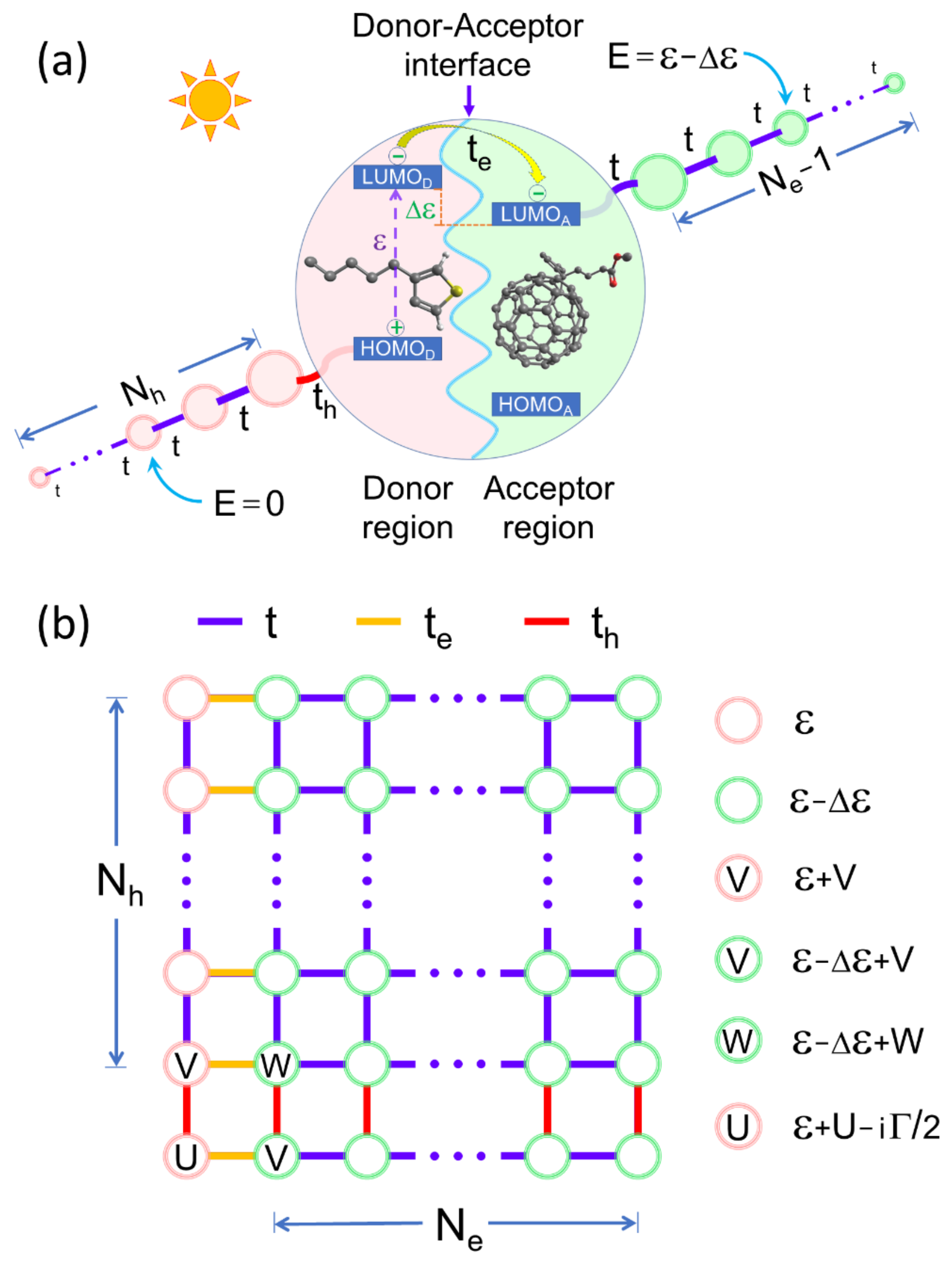
2. The Model
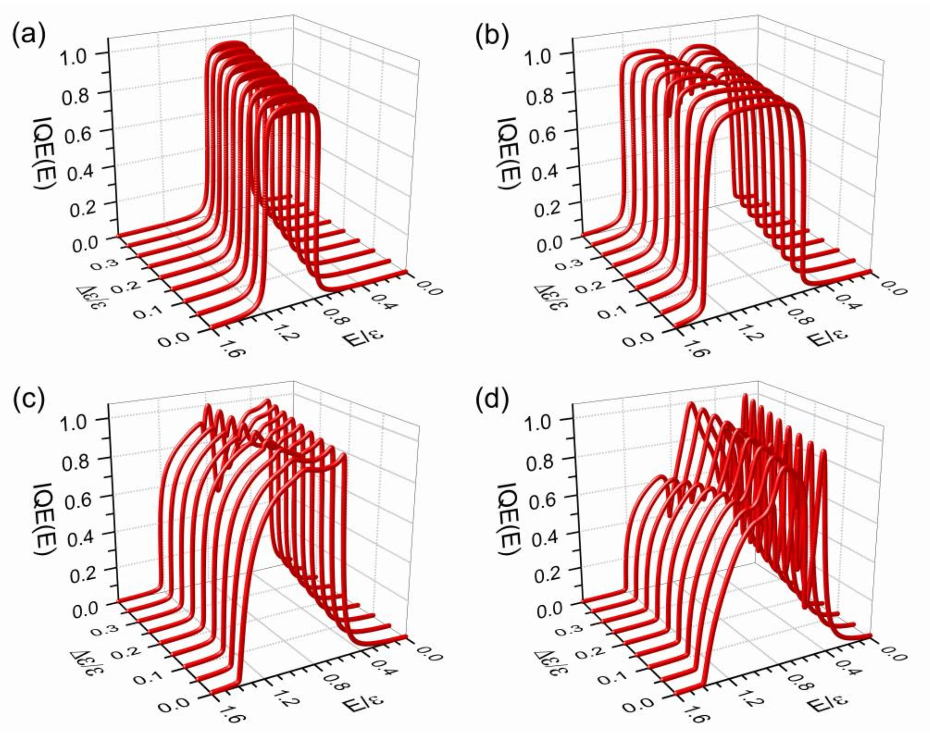
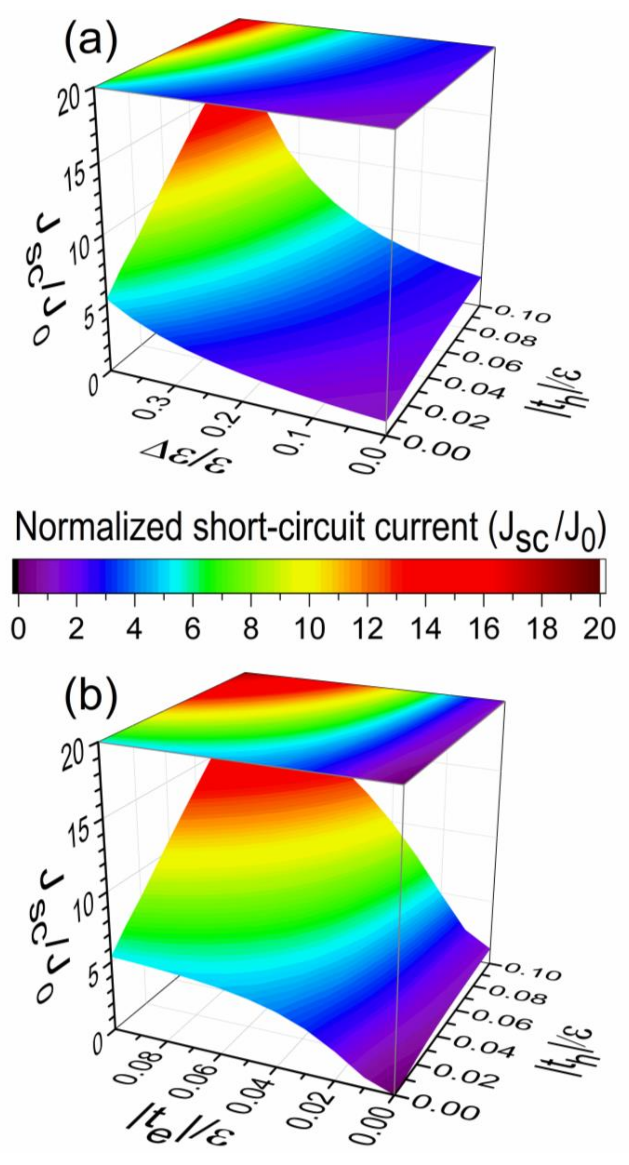
3. Numerical and Analytical Results
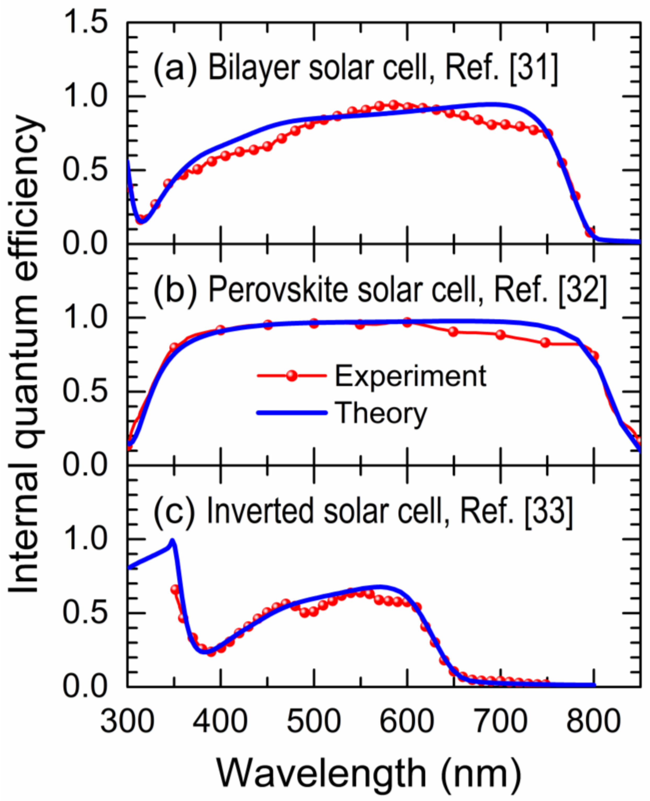
4. Theory Versus Experiments
5. Conclusions
Author Contributions
Funding
Institutional Review Board Statement
Informed Consent Statement
Data Availability Statement
Acknowledgments
Conflicts of Interest
Appendix A. Effective Chain Method

Appendix B. Analytical Solution of Short-Circuit Current
References
- Luther, J.M.; Johnson, J.C. An exciting boost for solar cells. Nature 2019, 571, 38–39. [Google Scholar] [CrossRef] [PubMed]
- Gao, J.; Wang, J.; Xu, C.; Hu, Z.; Ma, X.; Zhang, X.; Niu, L.; Zhang, J.; Zhang, F. A critical review on efficient thick-film organic solar cells. Sol. RRL 2020, 4, 2000364. [Google Scholar] [CrossRef]
- Green, M.A.; Dunlop, E.D.; Hohl-Ebinger, J.; Yoshita, M.; Kopidakis, N.; Hao, X. Solar cell efficiency tables (Version 56). Prog. Photovolt. Res. Appl. 2020, 28, 629–638. [Google Scholar] [CrossRef]
- Marrocchi, A.; Lanari, D.; Facchetti, A.; Vaccaro, L. Poly(3-hexylthiophene): Synthetic methodologies and properties in bulk heterojunction solar cells. Energy Environ. Sci. 2012, 5, 8457–8474. [Google Scholar] [CrossRef]
- Zhang, M.; Guo, X.; Ma, W.; Ade, H.; Hou, J. A large-bandgap conjugated polymer for versatile photovoltaic applications with high performance. Adv. Mater. 2015, 27, 4655. [Google Scholar] [CrossRef]
- Li, C.Z.; Yip, H.L.; Jen, A.K. Functional fullerenes for organic photovoltaics. J. Mater. Chem. 2012, 22, 4161–4177. [Google Scholar] [CrossRef]
- Yuan, J.; Zhang, Y.; Zhou, L.; Zhang, G.; Yip, H.-L.; Lau, T.-K.; Lu, X.; Zhu, C.; Peng, H.; Johnson, P.A.; et al. Single-junction organic solar cell with over 15% efficiency using fused-ring acceptor with electron-deficient core. Joule 2019, 3, 1140–1151. [Google Scholar] [CrossRef]
- Zhao, F.; Wang, C.; Zhan, X. Morphology control in organic solar cells. Adv. Energy Mater. 2018, 8, 1703147. [Google Scholar] [CrossRef]
- Gasparini, N.; Salleo, A.; McCulloch, I.; Baran, D. The role of the third component in ternary organic solar cells. Nat. Rev. Mater. 2019, 4, 229–242. [Google Scholar] [CrossRef]
- Chi, C.-Y.; Chen, M.-C.; Liaw, D.-J.; Wu, H.-Y.; Huang, Y.-C.; Tai, Y. A bifunctional copolymer additive to utilize photoenergy transfer and to improve hole mobility for organic ternary bulk-heterojunction solar cell. ACS Appl. Mater. Interfaces 2014, 6, 12119–12125. [Google Scholar] [CrossRef]
- Tang, C.W.; VanSlyke, S.A. Organic electroluminescent diodes. Appl. Phys. Lett. 1987, 51, 913–915. [Google Scholar] [CrossRef]
- Yu, G.; Gao, J.; Hummelen, J.C.; Wudi, F.; Heeger, A.J. Polymer photovoltaic cells: Enhanced efficiencies via a network of internal donor-acceptor heterojunctions. Science 1995, 270, 1789–1791. [Google Scholar] [CrossRef]
- Xu, H.; Yuan, F.; Zhou, D.; Liao, X.; Chen, L.; Chen, Y. Hole transport layers for organic solar cells: Recent progress and prospects. J. Mater. Chem. A 2020, 8, 11478–11492. [Google Scholar] [CrossRef]
- Liu, Q.; Jiang, Y.; Jin, K.; Qin, J.; Xu, J.; Li, W.; Xiong, J.; Liu, J.; Xiao, Z.; Sun, K.; et al. 18% Efficiency organic solar cells. Sci. Bull. 2020, 65, 272–275. [Google Scholar] [CrossRef]
- Wang, T.; Kupgan, G.; Brédas, J.-L. Organic photovoltaics: Relating chemical structure, local morphology, and electronic properties. Trends Chem. 2020, 2, 535–554. [Google Scholar] [CrossRef]
- Sen, K.; Crespo-Otero, R.; Weingart, O.; Thiel, W.; Barbatti, M. Interfacial states in donor−acceptor organic heterojunctions: Computational insights into thiophene-oligomer/fullerene junctions. J. Chem. Theory Comput. 2013, 9, 533–542. [Google Scholar] [CrossRef]
- Few, S.; Frost, J.M.; Kirkpatrick, J.; Nelson, J. Influence of chemical structure on the charge transfer state spectrum of a polymer:fullerene complex. J. Phys. Chem. C 2014, 16, 8253–8261. [Google Scholar] [CrossRef]
- Li, X.; Weng, K.; Ryu, H.S.; Guo, J.; Zhang, X.; Xia, T.; Fu, H.; Wei, D.; Min, J.; Zhang, Y.; et al. Non-fullerene organic solar cells based on benzo[1,2-b:4,5-b′]difuran-conjugated polymer with 14% efficiency. Adv. Funct. Mater. 2020, 30, 1906809. [Google Scholar]
- Marmolejo-Valencia, A.F.; Mata-Pinzón, Z.; Dominguez, L.; Amador-Bedolla, C. Atomistic simulations of bulk heterojunctions to evaluate the structural and packing properties of new predicted donors in OPVs. Phys. Chem. Chem. Phys. 2019, 21, 20315–20326. [Google Scholar] [CrossRef]
- Ramsey, J.L. Between the fundamental and the phenomenological: The challenge of semi-empirical’ methods. Philos. Sci. 1997, 64, 627–653. [Google Scholar] [CrossRef]
- Sánchez, F.; Amador-Bedolla, C.; Sánchez, V.; Wang, C. On the role of driving force in molecular photocell. Phys. B Cond. Matter. 2020, 583, 412052. [Google Scholar]
- Aram, T.N.; Asgari, A.; Mayou, D. Charge separation in organic solar cells: Effects of Coulomb interaction, recombination and hole propagation. EPL 2016, 115, 18003. [Google Scholar] [CrossRef]
- Aram, T.N.; Asgari, A.; Ernzerhof, M.; Quémerais, P.; Mayou, D. Quantum modeling of two-level photovoltaic systems. EPJ Photovolt. 2017, 8, 85503. [Google Scholar] [CrossRef]
- Seideman, T.; Miller, W.H. Calculation of the cumulative reaction probability via a discrete variable representation with absorbing boundary conditions. J. Chem. Phys. 1992, 96, 4412–4422. [Google Scholar] [CrossRef]
- Navarro, O.; Wang, C. An exact method to solve the diluted extended Hubbard model. Solid State Commun. 1992, 83, 473–478. [Google Scholar] [CrossRef]
- Hajjiah, A.; Kandas, I.; Shehata, N. Efficiency enhancement of perovskite solar cells with plasmonic nanoparticles: A simulation Study. Materials 2018, 11, 1626. [Google Scholar]
- Gilot, J.; Wienk, M.M.; Janssen, R.A.J. Measuring the external quantum efficiency of two-terminal polymer tandem solar cells. Adv. Funct. Mater. 2010, 20, 3904–3911. [Google Scholar] [CrossRef]
- Shi, L.; Liang, Q.; Wang, W.; Zhang, Y.; Li, G.; Ji, T.; Hao, Y.; Cui, Y. Research progress in organic photomultiplication photodetectors. Nanomaterials 2018, 8, 713. [Google Scholar] [CrossRef] [PubMed]
- Sánchez, V.; Wang, C. Real space theory for electron and phonon transport in aperiodic lattices via renormalization. Symmetry 2020, 12, 430. [Google Scholar]
- Sánchez, F.; Sánchez, V.; Wang, C. Exciton dissociation in correlated molecular photocells. J. Phys. Chem. Solids 2021, 152, 109966. [Google Scholar]
- Sun, S.; Salim, T.; Mathews, N.; Duchamp, M.; Boothroyd, C.; Xing, G.; Sum, T.C.; Lam, Y.M. The origin of high efficiency in low-temperature solution-processable bilayer organometal halide hybrid solar cells. Energy Environ. Sci. 2014, 7, 399–407. [Google Scholar] [CrossRef]
- Liu, Y.; Qian, J.; Zhang, H.; Xu, B.; Zhang, Y.; Liu, L.; Chen, G.; Tian, W. Influence of organic cations on intrinsic properties of lead iodide perovskite solar cells. Org. Electr. 2018, 62, 269–276. [Google Scholar] [CrossRef]
- Anefnaf, I.; Aazou, S.; Schmerber, G.; Refki, S.; Zimmermann, N.; Heiser, T.; Ferblantier, G.; Slaoui, A.; Dinia, A.; Abd-Lefdil, M.; et al. Polyethylenimine-ethoxylated interfacial layer for efficient electron collection in SnO2-based inverted organic solar cells. Crystals 2020, 10, 731. [Google Scholar] [CrossRef]
- Wong, F.; Perez, G.; Bonilla, M.; Colon-Santana, J.A.; Zhang, X.; Sharma, P.; Gruverman, A.; Dowben, P.A.; Rosa, L.G. Changing molecular band offsets in polymer blends of (P3HT/P(VDF-TrFE)) poly(3-hexylthiophene) and poly(vinylidene fluoride with trifluoroethylene) due to ferroelectric poling. RSC Adv. 2014, 4, 3020–3027. [Google Scholar] [CrossRef]
- Ansari, M.A.; Mohiuddin, S.; Kandemirli, F.; Malik, M.I. Synthesis and characterization of poly(3-hexylthiophene): Improvement of regioregularity and energy band gap. RSC Adv. 2018, 8, 8319–8328. [Google Scholar]
- The American Society for Testing and Materials (ASTM). G-173-03 Global Solar Irradiance Spectrum (Wm−2nm−1) on 37° Sun-Facing Tilted Surface. Available online: https://www.nrel.gov/grid/solar-resource/spectra-am1.5.html (accessed on 27 December 2020).


Publisher’s Note: MDPI stays neutral with regard to jurisdictional claims in published maps and institutional affiliations. |
© 2021 by the authors. Licensee MDPI, Basel, Switzerland. This article is an open access article distributed under the terms and conditions of the Creative Commons Attribution (CC BY) license (http://creativecommons.org/licenses/by/4.0/).
Share and Cite
Sánchez, F.; Sánchez, V.; Wang, C. Coarse-Grained Quantum Theory of Organic Photovoltaic Devices. Nanomaterials 2021, 11, 495. https://doi.org/10.3390/nano11020495
Sánchez F, Sánchez V, Wang C. Coarse-Grained Quantum Theory of Organic Photovoltaic Devices. Nanomaterials. 2021; 11(2):495. https://doi.org/10.3390/nano11020495
Chicago/Turabian StyleSánchez, Fernando, Vicenta Sánchez, and Chumin Wang. 2021. "Coarse-Grained Quantum Theory of Organic Photovoltaic Devices" Nanomaterials 11, no. 2: 495. https://doi.org/10.3390/nano11020495
APA StyleSánchez, F., Sánchez, V., & Wang, C. (2021). Coarse-Grained Quantum Theory of Organic Photovoltaic Devices. Nanomaterials, 11(2), 495. https://doi.org/10.3390/nano11020495