1. Introduction
A promising heat-assisted magnetic recording (HAMR) hard drive with L1
0 FePt media will come to the market soon. The [001] textured FePt film shows a moderate Curie temperature (<750 K) and a high perpendicular magnetocrystalline anisotropy (K
u) of 5 × 10
7 erg/cm
3, which make sure the grains are thermally stable down to 3 nm [
1,
2,
3,
4,
5]. The advantage of FePt media is its higher area density (~2 Tb/in
2) than conventional perpendicular magnetic recording (PMR). To ensure much higher area density in the future, the FePt media needs to have a specific microstructure, and tunable intrinsic and extrinsic magnetic properties. Intrinsically, the ordered L1
0 FePt grains with out-of-plane c-axis alignment were required to promote high-perpendicular magnetic anisotropy with a lower in-plane magnetic component. High-temperature deposition and annealing are an appropriate method to achieve high-ordered FePt film, but they also enhance the growth of the grains. To avoid coarse grains, suitable segregants are necessary to separate and refine the FePt grains in a uniformly granular and columnar structure.
The B
4C compound was used as an interlayer, a capping-layer, and the doping material, together with (Ag, C) segregants [
6,
7,
8], and the [001] textured FePt granular structure was formed on varied MgO-like intermediate layers after high-temperature deposition [
9,
10,
11,
12,
13,
14,
15]. In this work, a FePt(B, Ag, C) granular film was formed after the annealing of the capped B
4C/FePt(Ag, C) dual-layer. The C has a strong phase separation ability for a FePt film and the Ag was used to moderate the ordering degree. After high-temperature deposition and annealing, a 1 nm thick B
4C layer was diffused out in the atomic B and C in the FePt grains and boundaries, evidenced in electron energy loss spectroscopy (EELS) mapping [
16]. The Fe–B compound was observed in the X-ray photoelectron spectroscopy (XRS) spectra and evidenced in the tiny kink of the FePt (8 nm) magnetic hysteresis loops [
16].
The FePt(B, Ag, C) granular film was prepared in a novel way by the diffusion of B, N and C atoms between the B
4C capping layer and the MgTiON underlayer, and the switching field distribution (SFD) behavior of this film has rarely been discussed before. The correlation of grains size and magnetic clusters is investigated and well discussed in this work. Reducing the switching field distribution (SFD), which includes the intrinsic and extrinsic properties of the FePt grains, can improve the media noise [
4,
17,
18]. In this study, the average switching field defined by out-of-plane H
c was obtained in the major magnetic hysteresis loop, and the switching field distribution (SFD) was examined to further understand the magnetic characteristic via magnetic minor loops measurement [
4,
17,
18]. The intrinsic part of SFD includes the contribution of anisotropy filed dispersion, out-of-plane c-axis misalignment, and grain size distribution [
18]. The grains’ dipole and exchange coupling belong to the extrinsic contribution of SFD [
18]. Furthermore, the magnetization reversal process was tested by the linear tendency of the temperature dependence of coercivity, and the microstructural parameter was obtained after linear fitting [
19,
20,
21]. The discussion of a microstructural parameter can be correlated to the FePt grains images.
2. Materials and Methods
Magnetron sputtering was used to deposit the B4C/FePt(Ag, C)/MgTiON/CrRu films on a glass substrate with the argon working pressure of 10−2–10−3 Torr. The high vacuum sputtering system was designed with a main chamber background pressure of 1 × 10⁻⁷ Torr and the load-lock system was used to transfer the substrate via a pre-chamber. The multiple sputtering sources (A320, AJA INTERNATIONAL INC, MA, USA, MAK 2”, US Technologies West, San Jose, CA, USA) with 2 inch diameters were set up on the main chamber and the substrate was heated via a halogen lamp (1000W, OSRAM GmbH, Munich, Germany) with a maximum heating temperature of 800 °C. The glass substrate (Eagle 2000, Corning Display Technologies, Taipei, Taiwan) with the dimension of 1 cm2 was cleaned with de-ionized water, acetone, and ethyl alcohol solvents step by step, and each round lasted 30 min with ultrasonic vibration. After cleaning, the substrate was dried under a nitrogen atmosphere.
The target compositions were Fe52Pt48, Ag, C, (Mg0.5Ti0.5) (O0.9N0.1), Cr83Ru17 and B4C, and the diameter was 2 inches. The deposition rate (v) and Ar working pressure (PAr) of each layer were set to 0.165 nm/s (60W-DC) (MDX500, Advanced Energy, Fort Collins, CO, USA), PAr = 3 mTorr for CrRu; 0.045 nm/s (100W-RF) (PFG 300 RF, Huettinger Elektronik, Freiburg, Germany), PAr = 10 mTorr for MgTiON; 0.088 nm/s (30W-DC), PAr = 3 mTorr for FePt and 0.035 nm/s (27W-DC) (MDX500, Advanced Energy, Fort Collins, CO, USA) for (Ag, C) 40 vol%; 0.022 nm/s (100W-RF) (PFG 300 RF, Huettinger Elektronik, Freiburg, Germany), PAr = 10 mTorr for B4C.
The 76 nm thick CrRu seed layer with (002) texture was sputtered at 290 °C on a glass substrate to promote the (002) textured MgTiON intermediate layer, which was deposited at 435 °C for 30 nm. The MgTiON film showed a face-centered cubic (fcc) structure with a lattice constant of 0.422 nm. The lattice parameter of the a-axis was 0.384 nm and the c-axis was 0.372 nm for the FePt film. The lattice misfits between the MgTiON/CrRu and FePt/MgTiON layers were around 3% and 9%, respectively. It is suggested that the MgTiON(002)/[100] layer was grown on a CrRu(002)/[110] seed layer epitaxially [
12]. Finally, the L1
0 FePt-40vol%(Ag, C) layer with thicknesses of 6 and 8 nm were heteroepitaxially grown on MgTiON at 470 °C. The 1 nm thick B
4C-capped layer was sputtered on the magnetic FePt(Ag, C) layer at 470 °C, and post-annealing was maintained for 2 min. After the diffusion of B, C and N atoms from the respective B
4C and MgTiON layers, the released B, C and N atoms caused lots of vacancies and defects inside the FePt film, which promoted the ordering degree and increased the coercivity [
16]. After high-temperature deposition, the ordered FePt(B, Ag, C) film had a granular structure.
The crystallographic structure, texture, and order parameters of FePt were investigated and estimated by X-ray diffraction (XRD), and the θ/2θ diffraction patterns were collected using a standard X-ray diffractometer (BRUKER, D8 Discover, Bruker, Billerica, MA, USA). Magnetic hysteresis loops in the hard-axis (in-plane) and easy-axis (out-of-plane) directions were measured at room temperature by using a superconducting quantum interference device (SQUID) magnetometer (MPMS-XL, Quantum design, San Diago, CA, USA). The microstructure of the films was quantified by using transmission electron microscopy (TEM, JEOL JEM-2010, Tokyo, Japan).
3. Results and Discussion
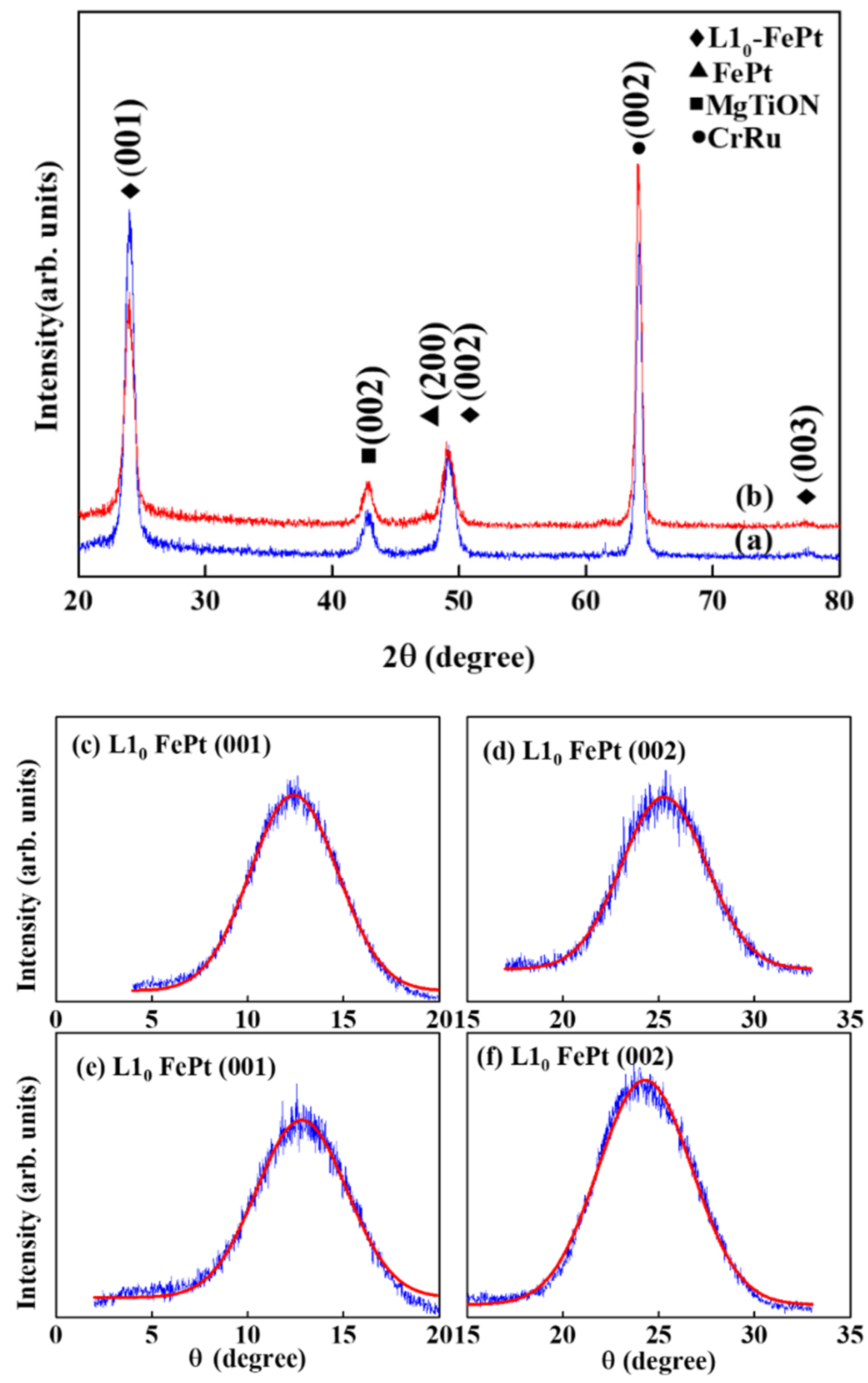
Figure 1 shows the XRD pattern of the FePt-(B, Ag, C)(
x nm)/MgTiON/CrRu films,
x = (a) 8 (b) 6. The (002) diffraction peaks of the CrRu seed layer and the MgTiON intermediate layer are illustrated, and the (001)/(003) superlattice and (002) fundamental diffraction peaks of the L1
0 FePt phase are exhibited.
The lattice misfit between FePt/MgTiON is 9%, and the FePt film is under tensile stress during ordering and grain growth. The FePt ordering degree is proportional to the [I(001)/I(002)]
1/2 ratio; here I(001) and I(002) are the integrated intensities of the FePt (001) and (002) diffraction peaks, and the ratio is 2.99 (the ordering values estimated from [(I
(001)/I
(002))/(I*
(001)/I*
(002))]
1/2 are 0.89 [
22,
23] and 2.87, respectively, shown in
Figure 1). The rocking curve was measured to evaluate the c-axis alignment of the FePt grains and the width (Δθ
50) was determined by measuring the full width at half maximum (FWHM) of the (001)/(002) reflection peaks; the measured values are 5.9°/5.7° and 5.7°/5.4°, as shown in
Figure 1c–f, respectively.
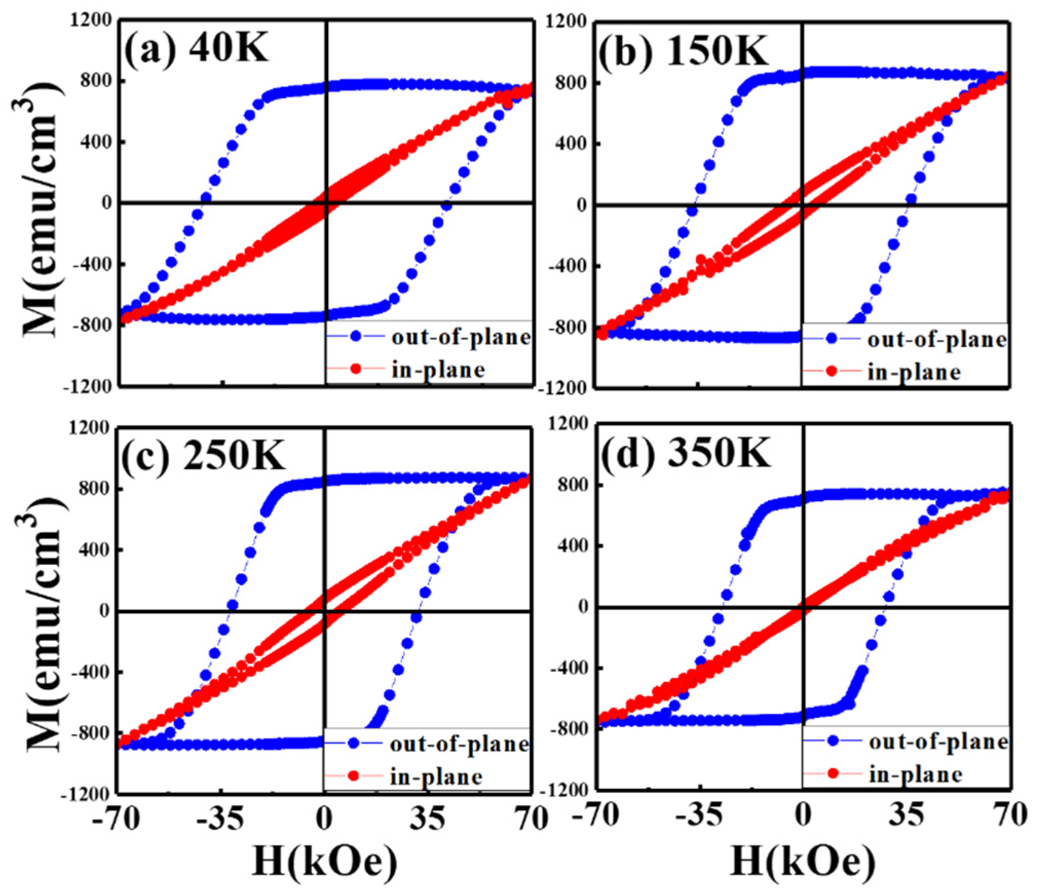
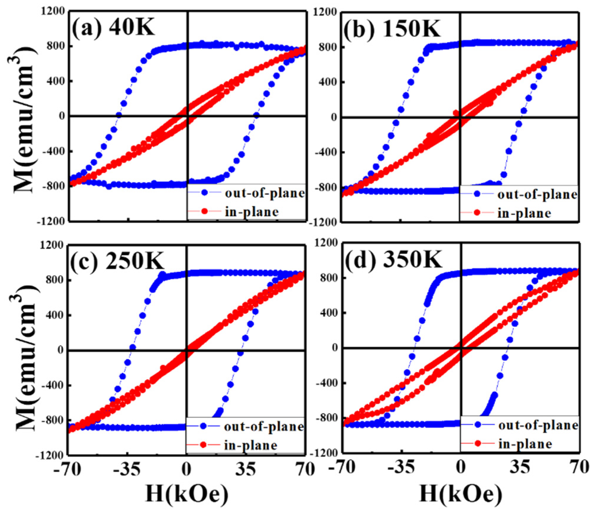
Figure 2 and
Figure 3 illustrate the magnetization hysteresis curves in the easy- and hard-magnetic axis of FePt-(B, Ag, C)(
x nm)/MgTiON/CrRu,
x = 8 and 6, measured from 40 K to 350 K. Two samples present perpendicular magnetic anisotropy with a high nucleation field in the easy-axis magnetic loops, and the hard-axis loop is linear-like with lower hysteresis.
The saturation magnetization (Ms) of two samples is around 800 emu/cm3, and the remanence ratio (Mr/Ms) is almost 1.0 for two samples. When the measured temperature is down to 40 K, the out-of-plane coercivity is around 40 kOe for both samples. Only the 6 nm thick FePt(B, Ag, C) film measured at 350 K shows a wide-up hard-axis loop that may be due to thermal instability.
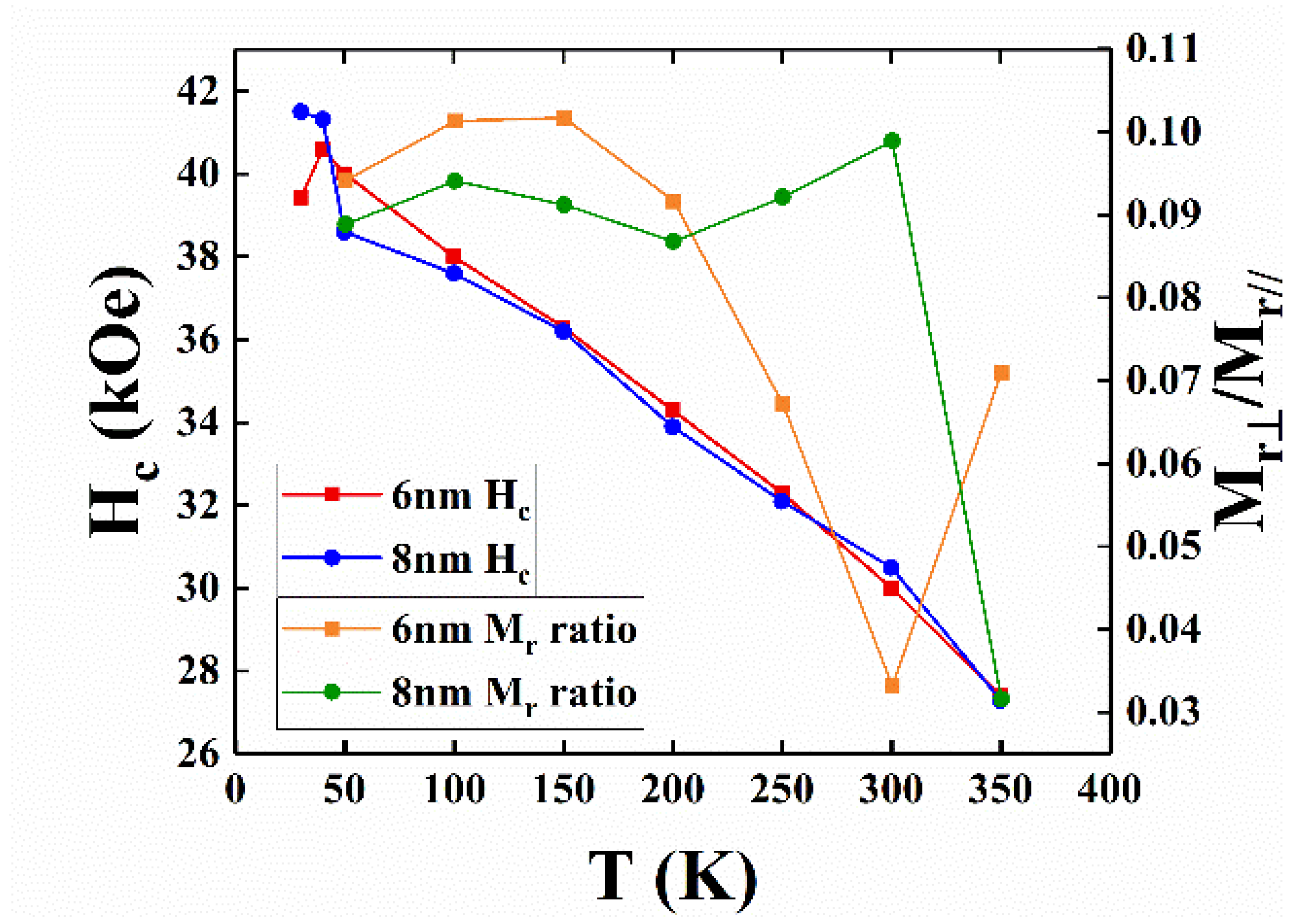
The temperature-dependence of out-of-plane coercivity is a plotted in
Figure 4. The out-of-plane H
c increased with decreasing the measured temperature from 350 K to 40 K, and the differences in the H
c values were between 0.1 and 0.5 kOe for the 6nm and 8 nm samples between 100 K and 350 K. The lower H
c of the 8 nm sample measured at 50 K was due to the formation of a minor Fe–B compound, and the larger average grain sizes (28.2 nm (for 8 nm sample); >23.3 nm (for 6 nm sample)).
The maximum applied field of 7 T was almost not enough to saturate the sample around 40 K, and the value of coercivity was for reference only. The tiny kink at the zero fields caused by the c-axis misalignment is observed in
Figure 2a–d, and is evidenced in the wider rocking width (Δθ
50 = 5.9°/5.7°) for the FePt-(B, Ag, C)(8 nm)/MgTiON/CrRu sample. The in-plane component was estimated by the ratio of in-plane to out-of-plane remanence (M
r(in-plane)/M
r(°
ut-°
f-plane)) [
16] and the values measured at different temperatures are plotted in
Figure 4. The remanence ratio ranged from 0.03 (3%) to 0.1(10%), and the c-axis of FePt grains aligned in an easy magnetization direction above 90%. The in-plane magnetization and c-axis misalignment may be due to the formation of a rare Fe–B compound or disordered FePt grains.
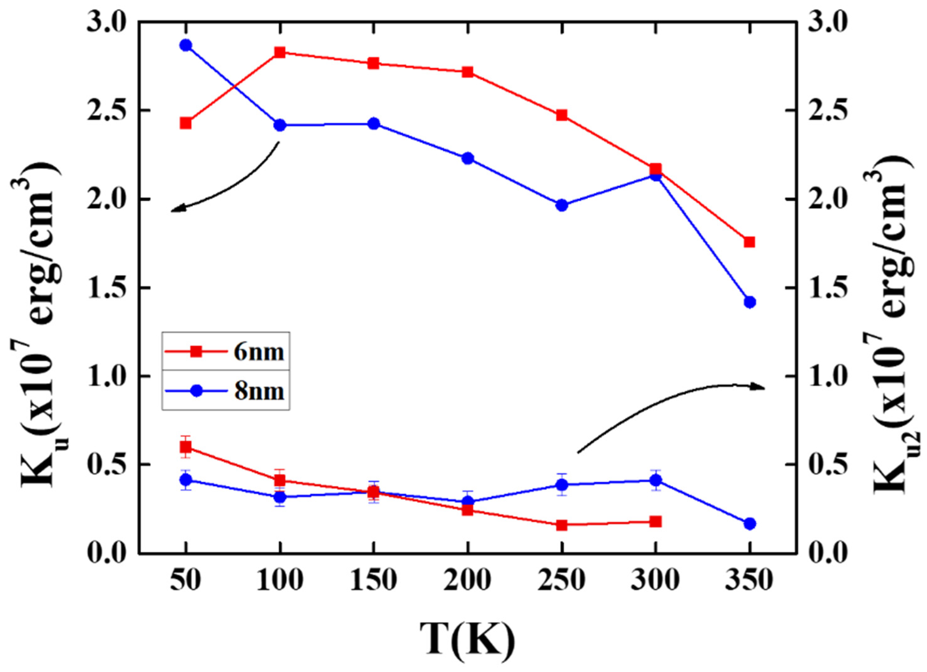
Figure 5 shows the temperature dependence of the magnetocrystalline anisotropy constant (K
u), and the anisotropy constant was determined as K
u = H
kM
s/2. Here, H
k is the anisotropy field estimated by the merge field of the in-plane and out-of-plane magnetization loops.
The L1
0 FePt-(B, Ag, C) films with thicknesses of 6 nm and 8 nm showed maximum K
u values of 2.83 × 10
7 erg/cm
3 at 100 K and 2.87 × 10
7 erg/cm
3 at 50 K, respectively, and the L1
0 FePt deposited on MgO(001) showed a higher K
u value (>3.5 × 10
7 erg/cm
3 in reference [
19]), which may due to the lesser amount of interface defects between FePt and the MgO single crystal.
For the 6 nm sample, the lower K
u (2.43 × 10
7 erg/cm
3) experimentally measured at 50 K was due to a larger error that occurred in the subtraction of the substrate effect of in-plane loops under a limited maximum applied field of 7 T [
16]. The K
u values decreased with the measured temperature and were down to 1.76 × 10
7 erg/cm
3 and 1.41 × 10
7 erg/cm
3 at 350 K for the respective 6 nm and 8 nm samples.
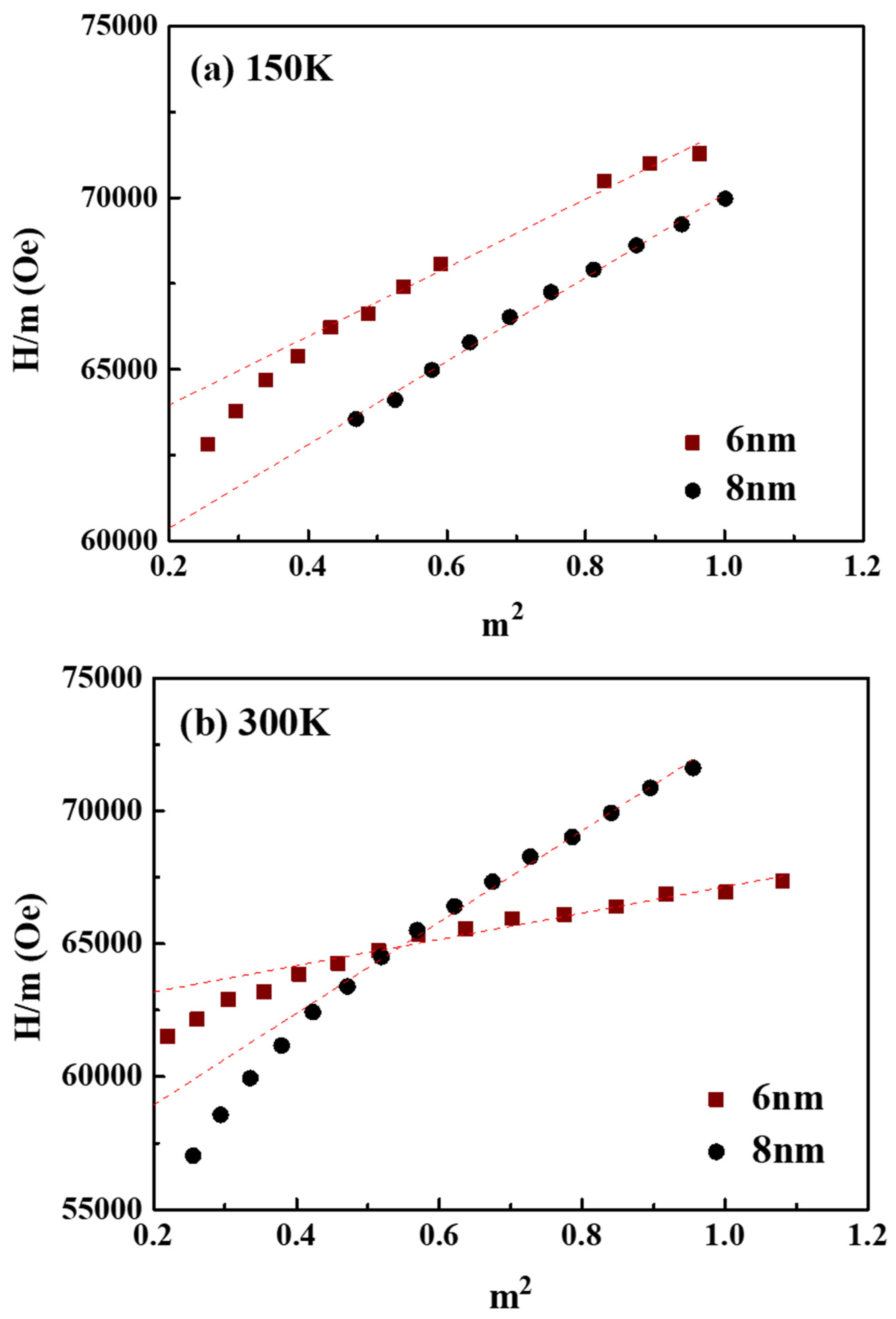
To disclose the magnetic anisotropy in the 6 nm and 8 nm samples, the second- and forth-order
, and
anisotropy constants were evaluated by plotting the hard-axis curve individually and shown in
Figure 5 and
Figure 6 [
24,
25].
where
m = is the reduced magnetization and
is the second-order anisotropy constant (Sucksmith–Thompson method). From the
H/m vs.
m2 plot, the
and
constants were determined by the intercept and the slope of the respective fitting curve [
24,
25]. The
K2/
K1 ratios of the 6 and 8 nm samples were 0.06 (
K2 = 1.79 × 10
6)/(
K1 = 2.67 × 10
7) and 0.10 (
K2 = 1.68 × 10
6)/(
K1 = 1.67 × 10
7) at 300 K, and they have the same value of 0.14 at 150 K. The small difference in
K2/
K1 ratio in the two samples means a near trend in the angular dependence of the switching field.
Figure 7 shows the plane view TEM images of the FePt-(B, Ag, C)(8 nm)/MgTiON/CrRu film. In
Figure 7a, the FePt grains are separated by the (Ag, C) at the grain boundary areas, and formed the granular structure. The average grain size was 28.2 nm and the average grain boundaries width was estimated by measuring the grains’ pitch δ (i.e., the center-to-center distance) [
16], with a value of 3.97 nm. In
Figure 7a,b, parts of the FePt grains were grown on the boundaries of MgTiON, and some FePt grains were interconnected in magnetic clusters with lengths in between 47.1 nm and 56.5 nm, which are near to the size of the clusters size (46.4 nm) estimated by Equation (3). The FePt grains’ morphology was polygon and polyhedral, due to the kinetics of grain growth. The lattice fringes in isolated and interconnected FePt grains were observed in
Figure 7c,d. The respective average lattice spacings (d
(110)) were 0.278 nm and 0.283 nm, and the grains’ lattice constant “
a” was 0.393 nm and 0.400 nm. For the same lattice constant “c” (0.384 nm), shown in
Figure 1a, the (c/a) ratios in
Figure 7c,d were 0.977 and 0.960, respectively. The interconnected FePt grains in
Figure 7d show a higher average ordering degree because the (c/a) ratio is disproportional to the ordering degree. It is suggested that the ordering degree was increased after the FePt grains’ growth and coursing. The grains boundaries were almost amorphous in
Figure 7c,d, but some lattice fringe can still be found in the boundary areas of
Figure 7d. The nano-beam diffraction patterns of the L1
0 FePt grains are shown in
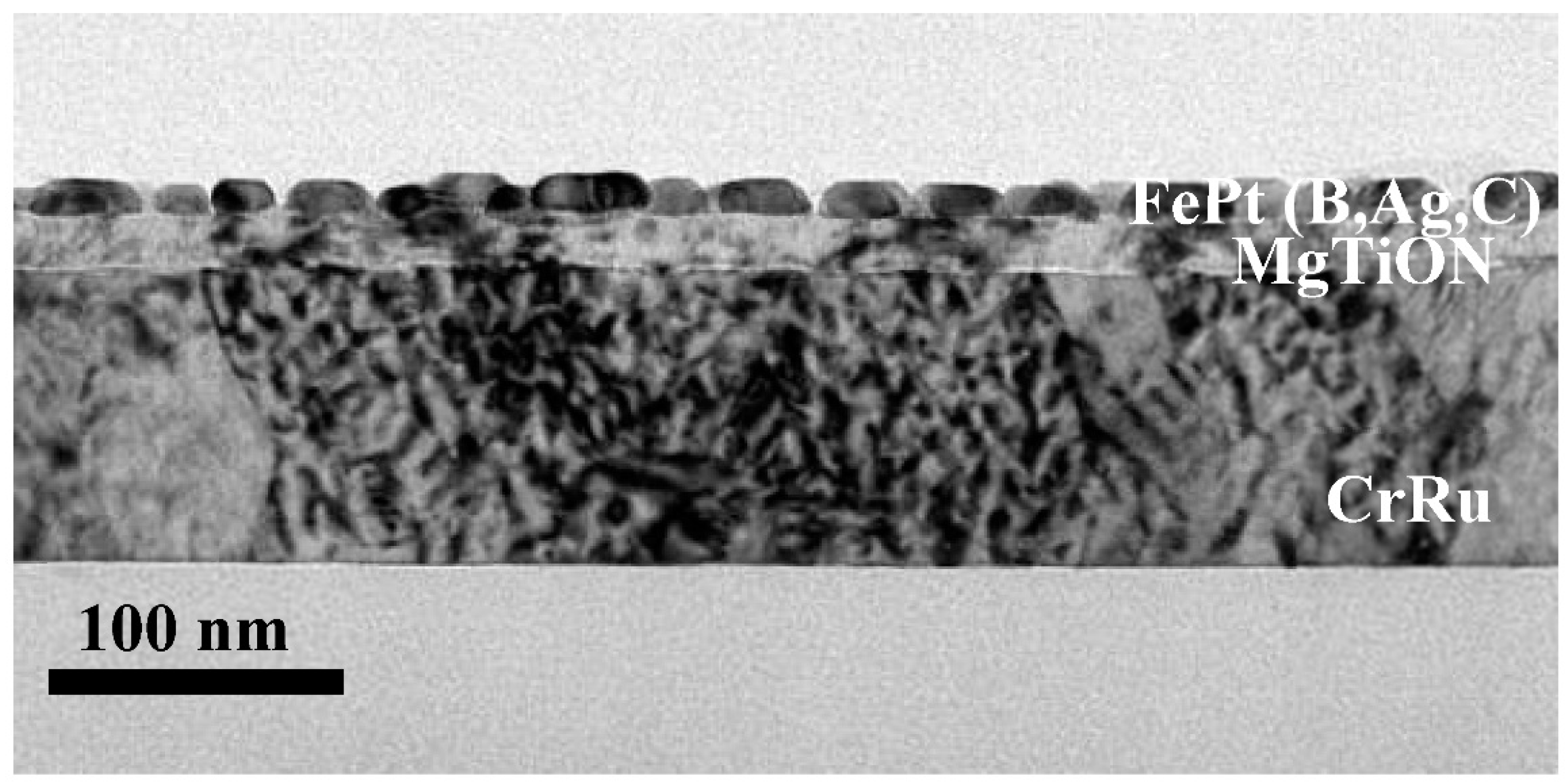
Figure 7e,f, and the (110), (200) and (220), and related symmetric planes, were indexed in the [001] zone axis. The cross-sectional TEM images of FePt(B, Ag, C)(8 nm)/MgTiON/CrRu are illustrated in
Figure 8, and the thickness of each layer was deposited based on the deposition rate and calibrated by the microstructure image.
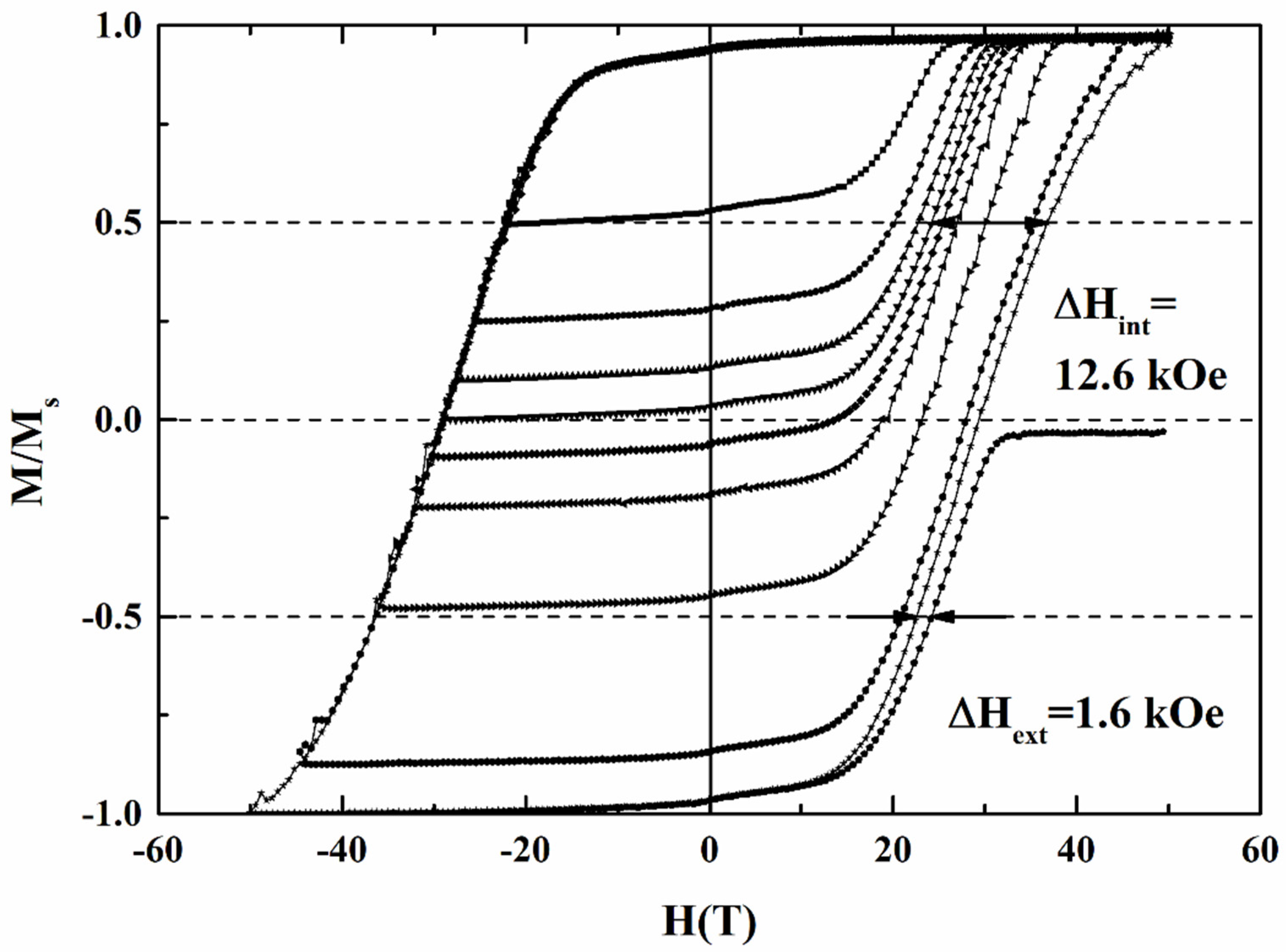
To understand the correlation between the magnetic switching behavior and grains’ morphology, we analyzed the switching field distribution (SFD), which comes from the intrinsic and extrinsic contribution of magnetic grains.
Figure 9 shows the major and minor magnetization loops of the FePt(B, Ag, C)(8 nm) film, and the intrinsic (ΔH
int = 12.6 kOe) and extrinsic (ΔH
ext = 1.62 kOe) switching field distributions were determined. The recoil loop in the coercivity field means the switching of 50% of the grains in the easy axis, and the demagnetization field between the grains, were neglected. As compared to the major magnetization loop, the parameters ΔH
int and ΔH
ext were collected. The intrinsic SFD arises from grain size distribution (σ
volume), magnetocrystalline anisotropy dispersion (σ
Hk) and misalignment of the c-axis(σ
axis), and the extrinsic SFD comes from the grains’ dipolar and exchange coupling [
4,
17]. The standard deviation (σ
int) of intrinsic SFD is 9.33 kOe (~21.2% of H
k), estimated from the ΔH
int/1.35 [
4,
17], and the (σ
int)
2 can be written as the summary of (σ
volume)
2 + (σ
axis)
2 + (σ
Hk)
2, which was the result of individual
Gaussian convolutions. The (σ
axis) was estimated by fitting the rocking curve FePt (002) peak measured by XRD (
Figure 1c–f), and the value is 4.55 kOe (~10.3% of H
k) after Gaussian fitting [
16].
The magnetization data were fitted to the modeled reversal curve in Equation (1) derived from reference [
17], and the (σ
volume) was extracted with the value of 1.23 kOe (~2.80% of H
k).
Finally, the magnetic anisotropic dispersion (σ
Hk)
2 can be estimated by (σ
int)
2 − (σ
volume)
2 − (σ
axis)
2, and the value of (σ
Hk) was 8.05 kOe, which is around 18.3% of the magnetic anisotropy field (H
k = 2K
u/M
s = 44.0 kOe). As compared to the misalignment of the c-axis and the grain size distribution, the magnetic anisotropy dispersion contributes to a higher intrinsic SFD. Base on the magnetic interactions in the perpendicular media [
4,
17], the ΔH
ext can be used to derive the magnetic cluster size (D
n), and the value of D
n was 46.6 nm in this sample. Equation (2) and (3), approximated from reference [
18], were used to calculate the magnetic cluster size.
In Equation (2), the extrinsic switching field distribution can be estimated by the internal effective field (H
in) acting on the selected target grains. The H
in includes the shape anisotropy field from the columnar grains (the term was neglected in Equation (2)), the total exchange field (H
ex) between the grains, and the magnetostatic field, which is divided into two terms, the local magnetostatic term (H
ms-local) and the long-range magnetostatic term (H
ms-long). The H
ex is balanced by H
ms-local, and the sum of these two terms is zero. Finally, we consider the long-range magnetostatic field as the main contribution of the extrinsic switching field, and the magnetic cluster size can be estimated by Equation (3). The magnetic cluster is larger than the average grains size (28.2 nm) and grains pitch (3.97 nm) [
16]. This indicates that there is a part of inter-granular coupling between grains.
Table 1 lists and compares the magnetic switching field behavior of the FePt(B, Ag, C) granular film and reference sample [
17]. The FePt(B, Ag, C)(8 nm) film shows a lower intrinsic field distribution than the reference FePt(Ag, C) film. It is suggested that the diffused B and N atoms improve the distribution in grain size, magnetocrystalline anisotropy and orientation. However, larger magnetic clusters and grains size were obtained after the high-temperature deposition of FePt(Ag, C, B) film.
The temperature dependency of coercivity was fitted by using the universal relation (seen in Equation (4)) to further understand the magnetization reversal process of the L1
0 FePt(B, Ag, C) film in detail [
19,
20,
21].
The experimental data plotted in
Figure 2,
Figure 3 and
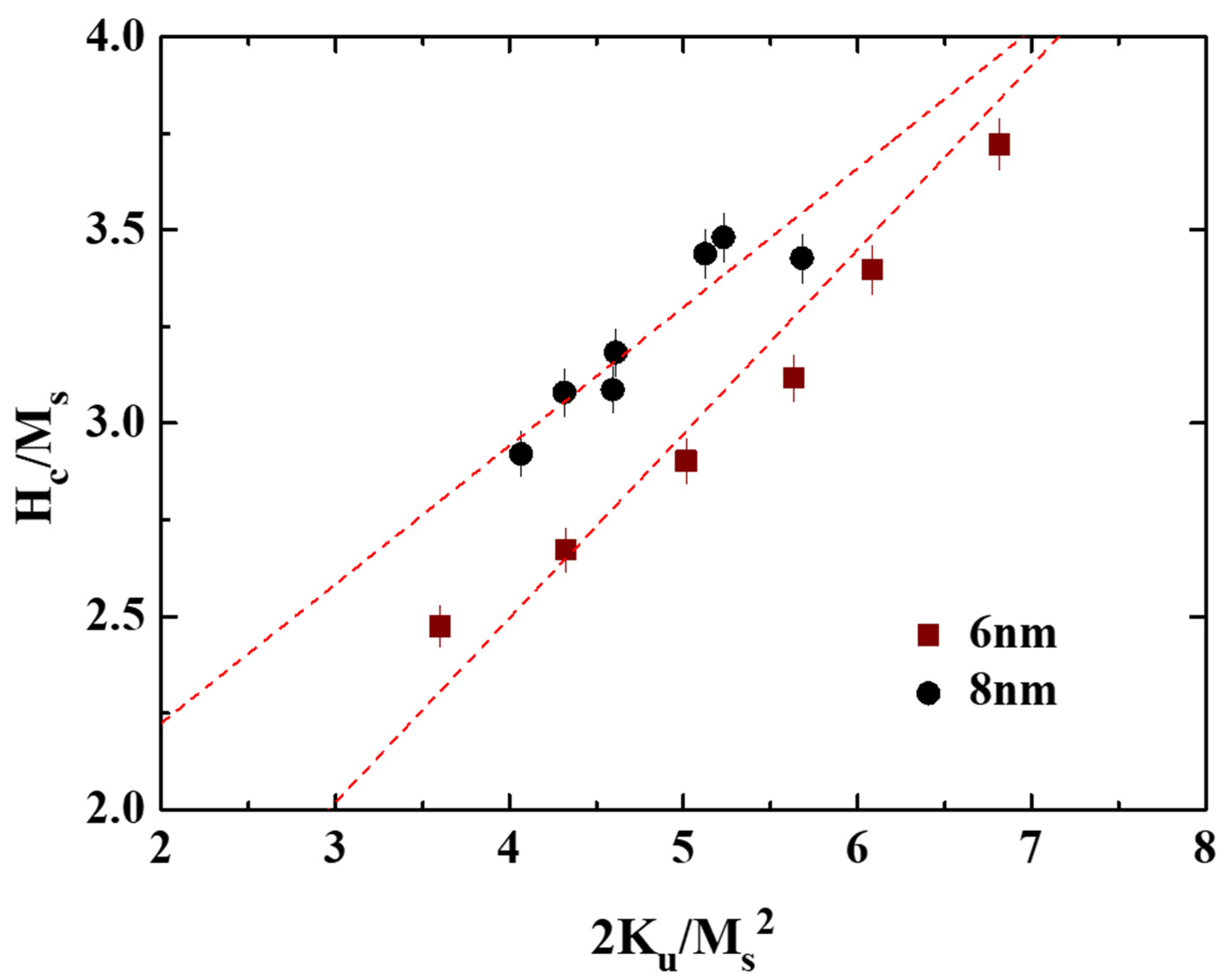
Figure 4 were used. The microstructural parameter was obtained as the slope of the linear fitting of H
c/M
s versus K
u/M
s2 in
Figure 10. The α values of the 8 nm and 6 nm samples are 0.36 and 0.58, respectively, and the maximum α value of 0.54, shown in reference [
19], is 7 nm. The microstructure parameter is the convolution of reduced magnetocrystalline (α
K), the misalignment grains (α
ψ), and the grains exchange coupling (α
ex). For parameter (α
ψ), the rocking width shown in
Figure 1c–f is smaller for L1
0 FePt(B, Ag, C) films with a thickness of 6 nm, but the difference is only (0.2°/0.3°) for (001)/(002) diffraction peaks.
For parameter α
K, the 6 nm thick FePt(B, Ag, C) film shows a higher K
u as compared to the 8 nm sample. For parameter α
ex, the slightly soft Fe–B phase was observed (tiny kink in magnetization curves measured from 40 to 350 K) in the 8 nm sample, and the magnetic cluster (coupled grains) was observed in the TEM images (
Figure 7d). It is suggested that an imperfect grains morphology always existed in the 6 nm and 8 nm samples. After combining all the factors, the lower microstructure parameter for the 8 nm sample can be explained.
