


Fabrication and Characterization of Highly Porous Gyroid Scaffolds Composed of Deproteinized Bone Mineral

 ,
, 

Abstract
1. Introduction
2. Materials and Methods
2.1. Powder Processing and Characterization
2.2. Slurry Preparation
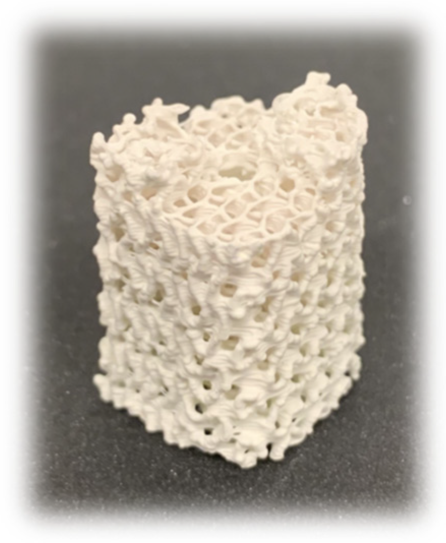
2.3. Scaffold Design and Fabrication
2.4. Scaffold Structure Characterization
2.4.1. Micro-Computed Tomography
2.4.2. Permeability
2.4.3. Compression Testing
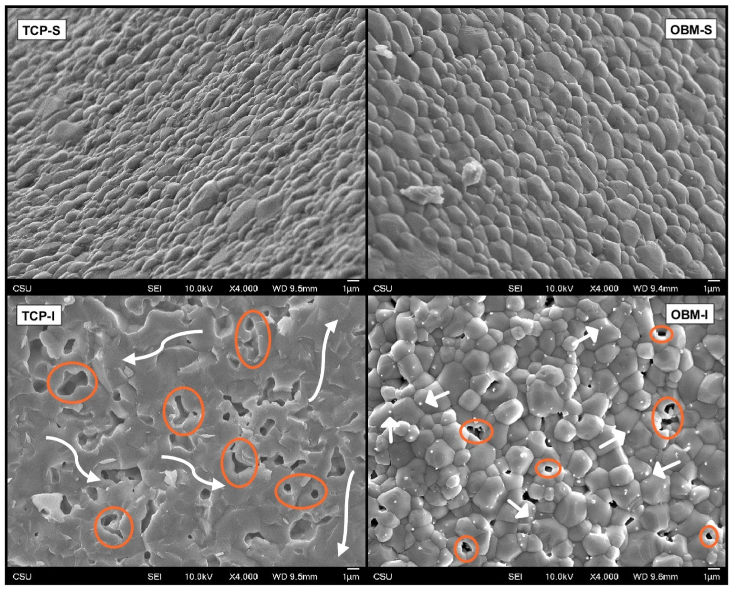
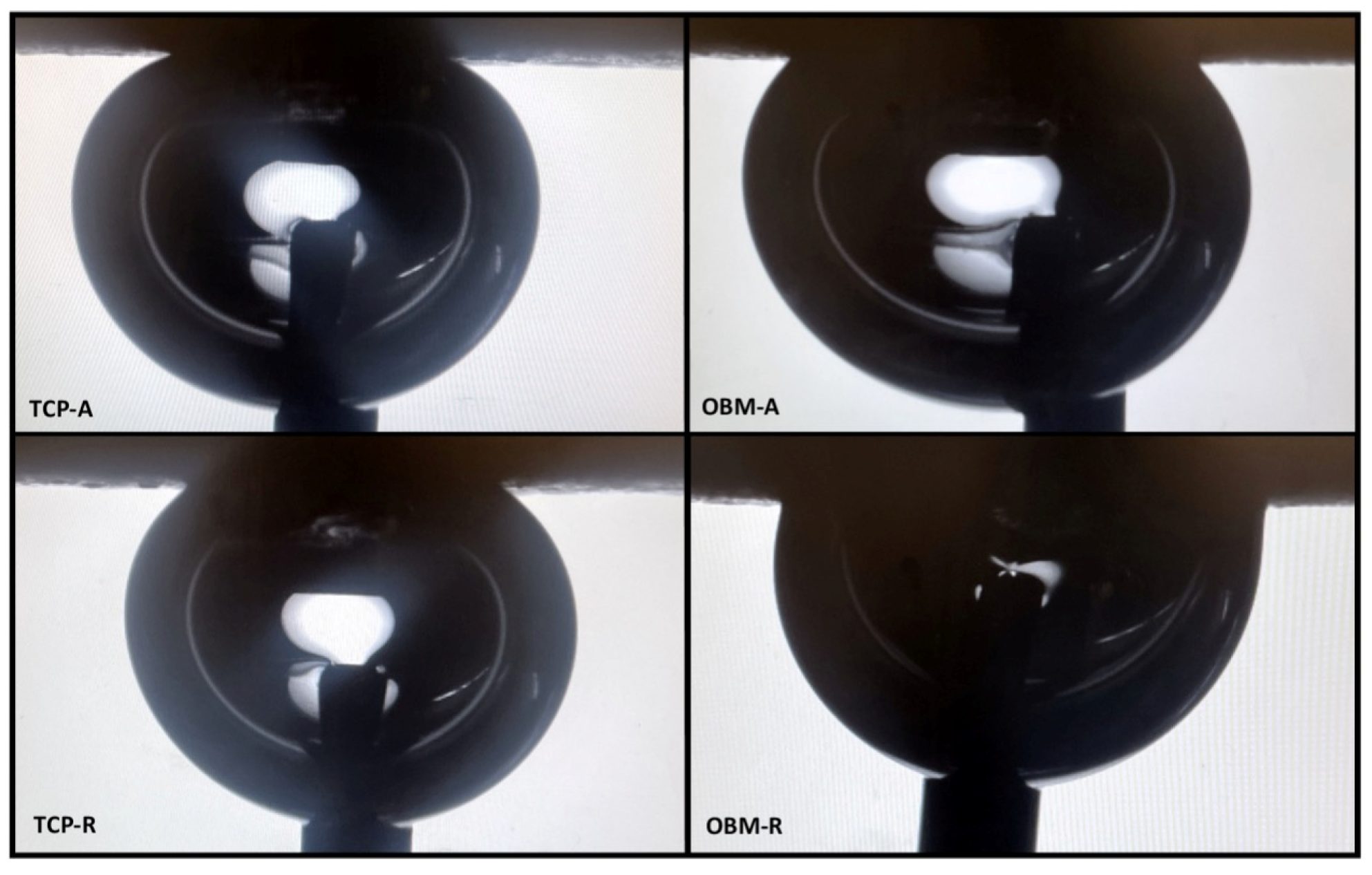
2.5. Surface Analysis
2.6. Statistical Analysis
3. Results
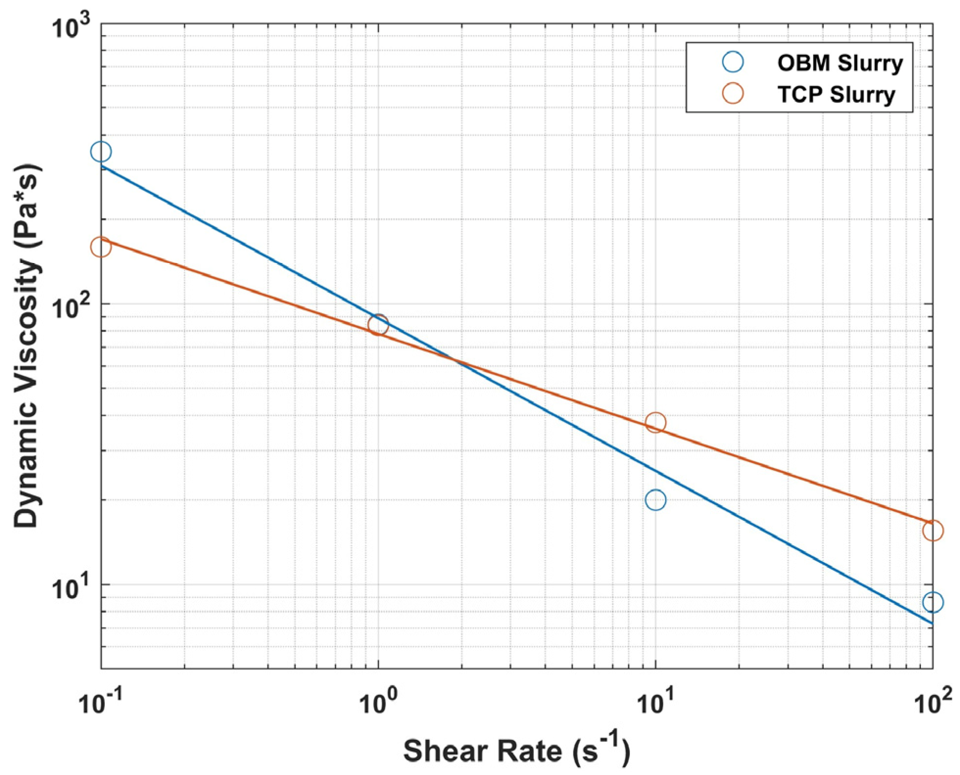
3.1. Powder Characterization and Rheological Behavior
3.2. Scaffold Structure Characterization
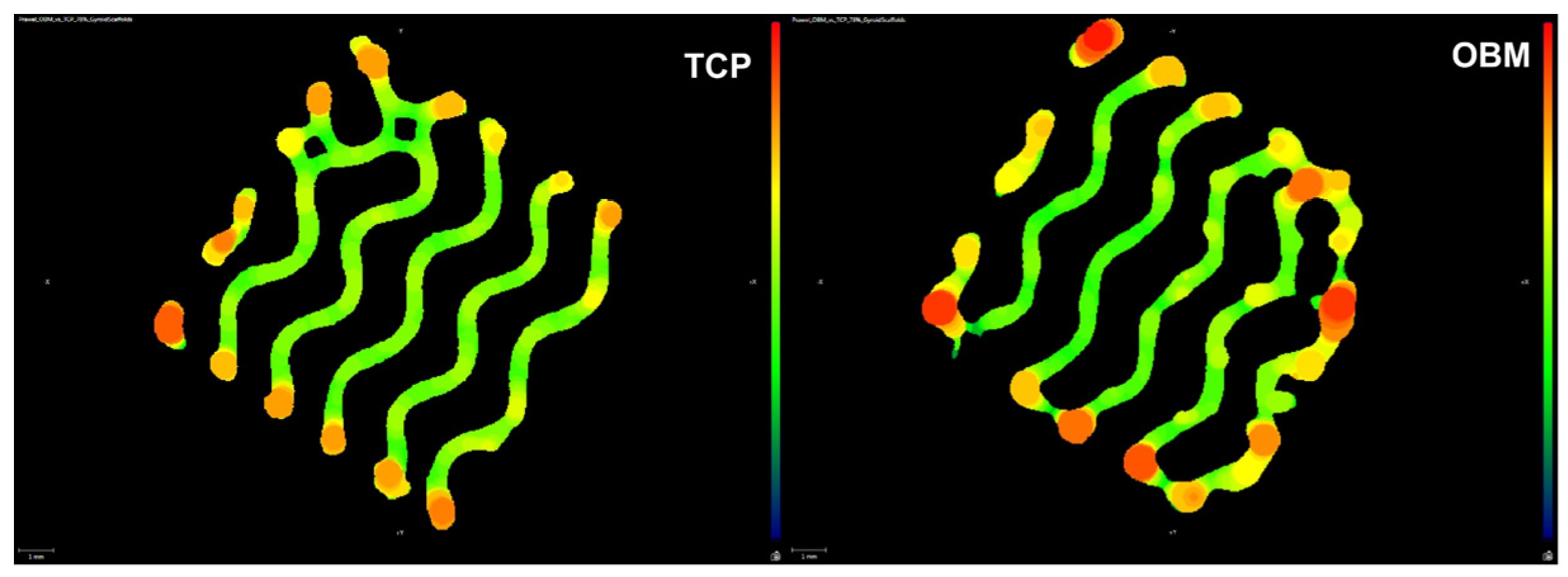
3.2.1. Micro-Computed Tomography
3.2.2. Shrinkage
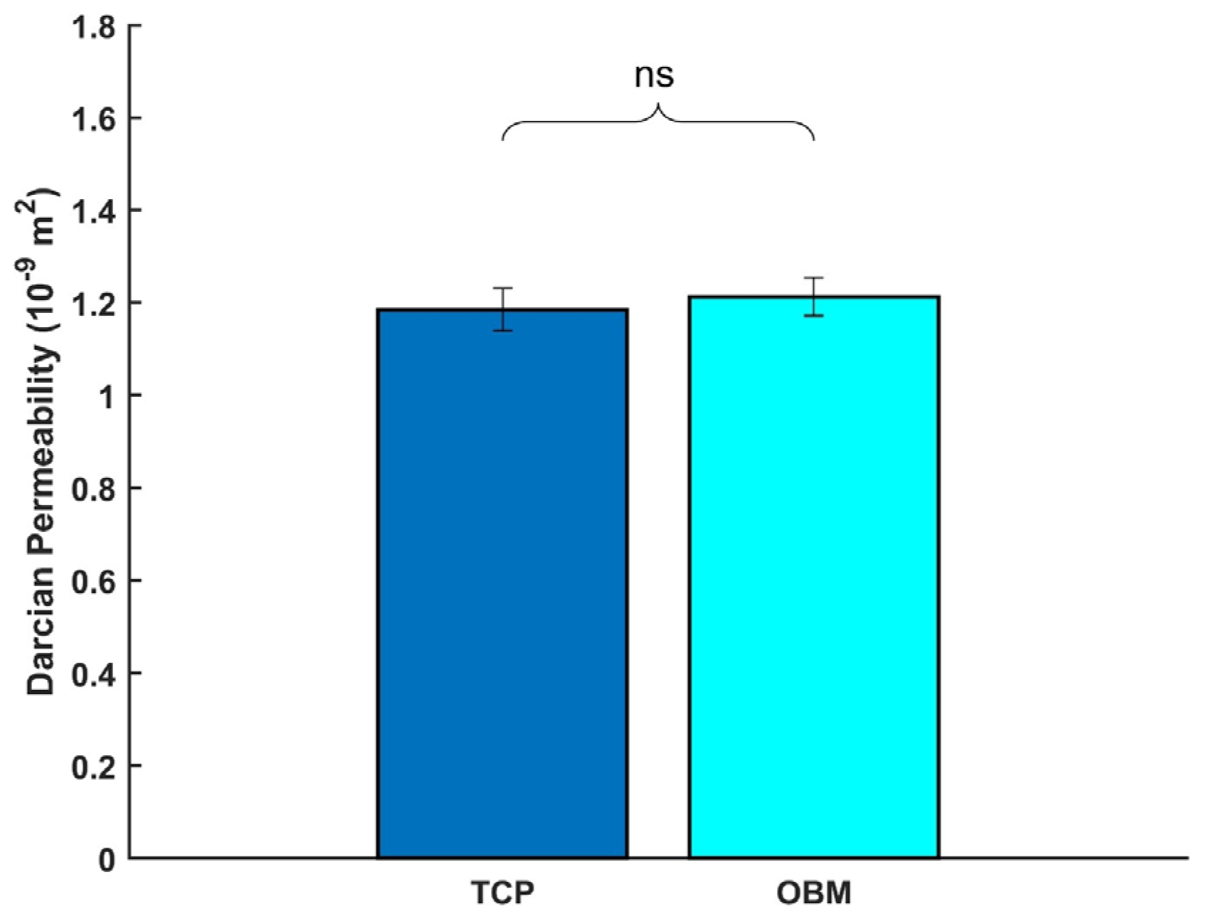
3.2.3. Permeability
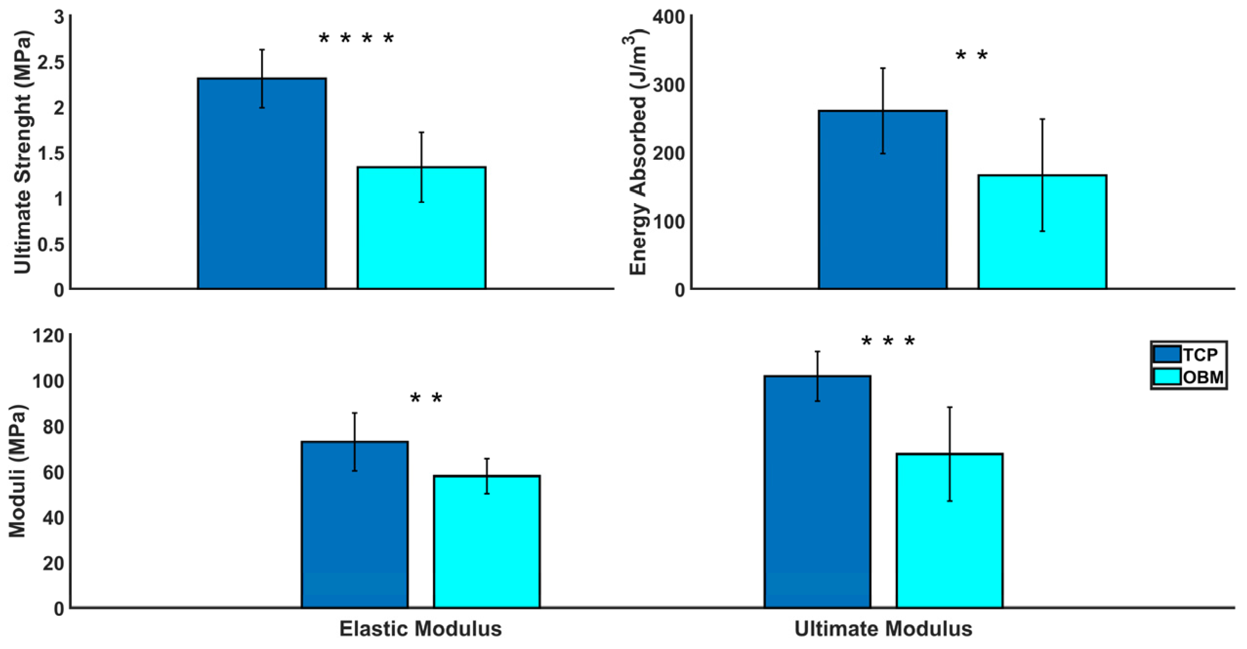
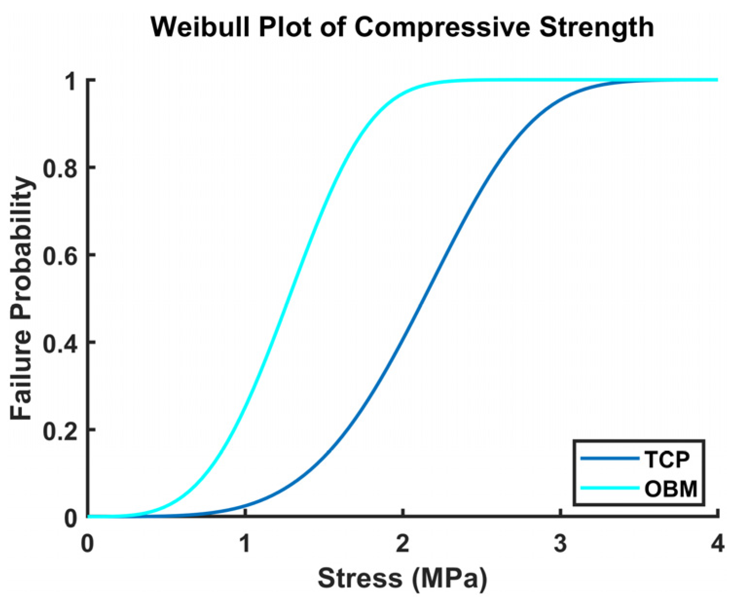
3.2.4. Compression Testing
3.3. Surface Analysis
3.4. Statistical Analysis
4. Discussion
5. Conclusions
Author Contributions
Funding
Institutional Review Board Statement
Data Availability Statement
Acknowledgments
Conflicts of Interest
References
- Ekegren, C.L.; Edwards, E.R.; De Steiger, R.; Gabbe, B.J. Incidence, Costs and Predictors of Non-Union, Delayed Union and Mal-Union Following Long Bone Fracture. Int. J. Environ. Res. Public Health 2018, 15, 2845. [Google Scholar] [CrossRef] [PubMed]
- Cauley, J.A. The global burden of fractures. Lancet Healthy Longev. 2021, 2, e535–e536. [Google Scholar] [CrossRef]
- Polaris Market Research. Bone Grafts and Substitutes Market Share, Size, Trends, Industry Analysis Report; Polaris Market Research: London, UK, 2024; Available online: https://www.polarismarketresearch.com/industry-analysis/bone-grafts-substitutes-market (accessed on 24 October 2024).
- Papakostidis, C.; Kanakaris, N.K.; Pretel, J.; Faour, O.; Morell, D.J.; Giannoudis, P.V. Prevalence of complications of open tibial shaft fractures stratified as per the Gustilo–Anderson classification. Injury 2011, 42, 1408–1415. [Google Scholar] [CrossRef] [PubMed]
- Vidal, L.; Kampleitner, C.; Brennan, M.Á.; Hoornaert, A.; Layrolle, P. Reconstruction of Large Skeletal Defects: Current Clinical Therapeutic Strategies and Future Directions Using 3D Printing. Front. Bioeng. Biotechnol. 2020, 8, 61. [Google Scholar] [CrossRef]
- Viateau, V.; Guillemin, G.; Yang, Y.C.; Bensaid, W.; Reviron, T.; Oudina, K.; Meunier, A.; Sedel, L.; Petite, H. A technique for creating critical-size defects in the metatarsus of sheep for use in investigation of healing of long-bone defects. Am. J. Vet. Res. 2004, 65, 1653–1657. [Google Scholar] [CrossRef]
- Wagels, M.; Rowe, D.; Senewiratne, S.; Theile, D.R. History of lower limb reconstruction after trauma: History of lower limb reconstruction after trauma. ANZ J. Surg. 2013, 83, 348–353. [Google Scholar] [CrossRef]
- Bose, S.; Ke, D.; Sahasrabudhe, H.; Bandyopadhyay, A. Additive manufacturing of biomaterials. Prog. Mater. Sci. 2018, 93, 45–111. [Google Scholar] [CrossRef]
- Germain, L.; Fuentes, C.A.; van Vuure, A.W.; des Rieux, A.; Dupont-Gillain, C. 3D-printed biodegradable gyroid scaffolds for tissue engineering applications. Mater. Des. 2018, 151, 113–122. [Google Scholar] [CrossRef]
- Abueidda, D.W.; Elhebeary, M.; Shiang, C.S.A.; Pang, S.; Abu Al-Rub, R.K.; Jasiuk, I.M. Mechanical properties of 3D printed polymeric Gyroid cellular structures: Experimental and finite element study. Mater. Des. 2019, 165, 107597. [Google Scholar] [CrossRef]
- Yuan, L.; Ding, S.; Wen, C. Additive manufacturing technology for porous metal implant applications and triple minimal surface structures: A review. Bioact. Mater. 2019, 4, 56–70. [Google Scholar] [CrossRef]
- Kolan, K.C.R.; Thomas, A.; Leu, M.C.; Hilmas, G. In vitro assessment of laser sintered bioactive glass scaffolds with different pore geometries. Rapid Prototyp. J. 2015, 21, 152–158. [Google Scholar] [CrossRef]
- Alizadeh-Osgouei, M.; Li, Y.; Vahid, A.; Ataee, A.; Wen, C. High strength porous PLA gyroid scaffolds manufactured via fused deposition modeling for tissue-engineering applications. Smart Mater. Med. 2021, 2, 15–25. [Google Scholar] [CrossRef]
- Kapfer, S.C.; Hyde, S.T.; Mecke, K.; Arns, C.H.; Schröder-Turk, G.E. Minimal surface scaffold designs for tissue engineering. Biomaterials 2011, 32, 6875–6882. [Google Scholar] [CrossRef]
- Maskery, I.; Sturm, L.; Aremu, A.O.; Panesar, A.; Williams, C.B.; Tuck, C.J.; Wildman, R.D.; Ashcroft, I.A.; Hague, R.J.M. Insights into the mechanical properties of several triply periodic minimal surface lattice structures made by polymer additive manufacturing. Polymer 2018, 152, 62–71. [Google Scholar] [CrossRef]
- Santos, J.; Pires, T.; Gouveia, B.P.; Castro, A.P.G.; Fernandes, P.R. On the permeability of TPMS scaffolds. J. Mech. Behav. Biomed. Mater. 2020, 110, 103932. [Google Scholar] [CrossRef]
- Olivares, A.L.; Marsal, È.; Planell, J.A.; Lacroix, D. Finite element study of scaffold architecture design and culture conditions for tissue engineering. Biomaterials 2009, 30, 6142–6149. [Google Scholar] [CrossRef]
- Ambrosio, K.V.L. Hydroxyapatite Structures Created by Additive Manufacturing with Extruded Photopolymer. Master’s Thesis, Colorado State University, Fort Collins, CO, USA, 2019. [Google Scholar]
- Isaacson, N.; Lopez-Ambrosio, K.; Chubb, L.; Waanders, N.; Hoffmann, E.; Witt, C.; James, S.; Prawel, D.A. Compressive properties and failure behavior of photocast hydroxyapatite gyroid scaffolds vary with porosity. J. Biomater. Appl. 2022, 37, 55–76. [Google Scholar] [CrossRef]
- Hollister, S.J. Porous scaffold design for tissue engineering. Nat. Mater. 2005, 4, 518–524. [Google Scholar] [CrossRef]
- Vorndran, E.; Moseke, C.; Gbureck, U. 3D printing of ceramic implants. MRS Bull. 2015, 40, 127–136. [Google Scholar] [CrossRef]
- Bandyopadhyay, A.; Bernard, S.; Xue, W.; Bose, S. Calcium Phosphate-Based Resorbable Ceramics: Influence of MgO, ZnO, and SiO2 Dopants: Calcium Phosphate-Based Resorbable Ceramics. J. Am. Ceram. Soc. 2006, 89, 2675–2688. [Google Scholar] [CrossRef]
- Bose, S.; Tarafder, S.; Banerjee, S.; Davies, N.M.; Bandyopadhyay, A. Understanding in vivo response and mechanical property variation in MgO, SrO and SiO2 doped β-TCP. Bone 2011, 48, 1282–1290. [Google Scholar] [PubMed]
- Tarafder, S.; Balla, V.K.; Davies, N.M.; Bandyopadhyay, A.; Bose, S. Microwave-sintered 3D printed tricalcium phosphate scaffolds for bone tissue engineering. J. Tissue Eng. Regen. Med. 2013, 7, 631–641. [Google Scholar] [CrossRef] [PubMed]
- Ke, D.; Tarafder, S.; Vahabzadeh, S.; Bose, S. Effects of MgO, ZnO, SrO, and SiO2 in tricalcium phosphate scaffolds on in vitro gene expression and in vivo osteogenesis. Mater. Sci. Eng. C 2019, 96, 10–19. [Google Scholar] [CrossRef]
- Bose, S.; Fielding, G.; Tarafder, S.; Bandyopadhyay, A. Understanding of dopant-induced osteogenesis and angiogenesis in calcium phosphate ceramics. Trends Biotechnol. 2013, 31, 594–605. [Google Scholar] [CrossRef]
- Banerjee, S.; Tarafder, S.; Davies, N.M.; Bandyopadhyay, A.; Bose, S. Understanding the influence of MgO and SrO binary doping on the mechanical and biological properties of β-TCP ceramics. Acta Biomater. 2010, 6, 4167–4174. [Google Scholar]
- Pietak, A.M.; Reid, J.W.; Stott, M.J.; Sayer, M. Silicon substitution in the calcium phosphate bioceramics. Biomaterials 2007, 28, 4023–4032. [Google Scholar] [CrossRef]
- Yamasaki, Y.; Yoshida, Y.; Okazaki, M.; Shimazu, A.; Uchida, T.; Kubo, T.; Akagawa, Y.; Hamada, Y.; Takahashi, J.; Matsuura, N. Synthesis of functionally graded MgCO3 apatite accelerating osteoblast adhesion. J. Biomed. Mater. Res. 2002, 62, 99–105. [Google Scholar] [CrossRef]
- Jegou Saint-Jean, S.; Camire, C.L.; Nevsten, P.; Hansen, S.; Ginebra, M.P. Study of the reactivity and in vitro bioactivity of Sr-substituted α-TCP cements. J. Mater. Sci. Mater. Med. 2005, 16, 993–1001. [Google Scholar] [CrossRef]
- Bandyopadhyay, A.; Withey, E.A.; Moore, J.; Bose, S. Influence of ZnO doping in calcium phosphate ceramics. Mater. Sci. Eng. C 2007, 27, 14–17. [Google Scholar] [CrossRef]
- Hanai, Y.; Tokuda, H.; Yasuda, E.; Noda, T.; Ohta, T.; Takai, S.; Kozawa, O. Up-regulation by zinc of FGF-2-induced VEGF release throughenhancing p44/p42 MAP kinase activation in osteoblasts. Life Sci. 2006, 80, 230–234. [Google Scholar] [CrossRef]
- Gao, T.; Aro, H.T.; Ylänen, H.; Vuorio, E. Silica-based bioactive glasses modulate expression of bone morphogenetic protein-2 mRNA in Saos-2 osteoblasts in vitro. Biomaterials 2001, 22, 1475–1483. [Google Scholar] [CrossRef] [PubMed]
- Gomes, P.S.; Botelho, C.; Lopes, M.A.; Santos, J.D.; Fernandes, M.H. Effect of silicon-containing hydroxyapatite coatings on the human in vitro osteoblastic response. Bone 2009, 44, S267. [Google Scholar] [CrossRef]
- Jones, J.R.; Tsigkou, O.; Coates, E.E.; Stevens, M.M.; Polak, J.M.; Hench, L.L. Extracellular matrix formation and mineralization on a phosphate-free porous bioactive glass scaffold using primary human osteoblast (HOB) cells. Biomaterials 2007, 28, 1653–1663. [Google Scholar] [CrossRef] [PubMed]
- Spector, M. Anorganic Bovine Bone and Ceramic Analogs of Bone Mineral as Implants to Facilitate Bone Regeneration. Clin. Plast. Surg. 1994, 21, 437–444. [Google Scholar] [CrossRef]
- Lopera-Echavarría, A.M.; Medrano-David, D.; Lema-Perez, A.M.; Araque-Marín, P.; Londoño, M.E. In vitro evaluation of confinement, bioactivity, and degradation of a putty type bone substitute. Mater. Today Commun. 2021, 26, 102105. [Google Scholar] [CrossRef]
- Liu, T.; Wu, G.; Wismeijer, D.; Gu, Z.; Liu, Y. Deproteinized bovine bone functionalized with the slow delivery of BMP-2 for the repair of critical-sized bone defects in sheep. Bone 2013, 56, 110–118. [Google Scholar] [CrossRef]
- Wu, G.; Hunziker, E.B.; Zheng, Y.; Wismeijer, D.; Liu, Y. Functionalization of deproteinized bovine bone with a coating-incorporated depot of BMP-2 renders the material efficiently osteoinductive and suppresses foreign-body reactivity. Bone 2011, 49, 1323–1330. [Google Scholar] [CrossRef]
- Simunek, A.; Kopecka, D.; Somanathan, R.V.; Pilathadka, S.; Brazda, T. Deproteinized Bovine Bone Versus Beta-Tricalcium Phosphate in Sinus Augmentation Surgery: A Comparative Histologic and Histomorphometric Study. Int. J. Oral Maxillofac. Implant. 2008, 23, 935–942. [Google Scholar]
- Karageorgiou, V.; Kaplan, D. Porosity of 3D biomaterial scaffolds and osteogenesis. Biomaterials 2005, 26, 5474–5491. [Google Scholar] [CrossRef]
- Carrel, J.; Wiskott, A.; Moussa, M.; Rieder, P.; Scherrer, S.; Durual, S. A 3D printed TCP-HA structure as a new osteoconductive scaffold for vertical bone augmentation. Clin. Oral Implant. Res. 2016, 27, 55–62. [Google Scholar] [CrossRef]
- Bohner, M.; Baroud, G.; Bernstein, A.; Dӧbelin, N.; Galea, L.; Hesse, B.; Heuberger, R.; Meille, S.; Michel, P.; von Rechenberg, B.; et al. Characterization and distribution of mechanically competent mineralized tissue in micropores of β-tricalcium phosphate bone substitutes. Mater. Today 2017, 20, 106–115. [Google Scholar]
- Vaquette, C.; Mitchell, J.; Ivanovski, S. Recent Advances in Vertical Alveolar Bone Augmentation Using Additive Manufacturing Technologies. Front. Bioeng. Biotechnol. 2022, 9, 798393. [Google Scholar] [CrossRef]
- Baumer, V.; Gunn, E.; Riegle, V.; Bailey, C.; Shonkwiler, C.; Prawel, D. Robocasting of Ceramic Fischer–Koch S Scaffolds for Bone Tissue Engineering. J. Funct. Biomater. 2023, 14, 251. [Google Scholar] [CrossRef] [PubMed]
- Moreno, R. Better ceramics through colloid chemistry. J. Eur. Ceram. Soc. 2020, 40, 559–587. [Google Scholar] [CrossRef]
- Al-Ketan, O.; Abu Al-Rub, R.K. Multifunctional Mechanical Metamaterials Based on Triply Periodic Minimal Surface Lattices. Adv. Eng. Mater. 2019, 21, 1900524. [Google Scholar] [CrossRef]
- ASTM E113-13; Test Methods for Determining Average Grain Size. ASTM International: West Conshohocken, PA, USA, 2013.
- Askeland, D.R.; Fulay, P.P.; Wright, W.J. The Science and Engineering of Materials, 6th ed.; Cengage Learning: Stamford, CT, USA, 2011. [Google Scholar]
- Doostmohammadi, A.; Monshi, A.; Salehi, R.; Fathi, M.H.; Karbasi, S.; Pieles, U.; Daniels, A.U. Preparation, chemistry and physical properties of bone-derived hydroxyapatite particles having a negative zeta potential. Mater. Chem. Phys. 2012, 132, 446–452. [Google Scholar] [CrossRef]
- Ramirez-Gutierrez, C.F.; Londoño-Restrepo, S.M.; Del Real, A.; Mondragón, M.A.; Rodriguez-García, M.E. Effect of the temperature and sintering time on the thermal, structural, morphological, and vibrational properties of hydroxyapatite derived from pig bone. Ceram. Int. 2017, 43, 7552–7559. [Google Scholar] [CrossRef]
- Buddhachat, K.; Klinhom, S.; Siengdee, P.; Brown, J.L.; Nomsiri, R.; Kaewmong, P.; Thitaram, C.; Mahakkanukrauh, P.; Nganvongpanit, K. Elemental Analysis of Bone, Teeth, Horn and Antler in Different Animal Species Using Non-Invasive Handheld X-Ray Fluorescence. PLoS ONE 2016, 11, e0155458. [Google Scholar] [CrossRef]
- Lakhkar, N.J.; Lee, I.-H.; Kim, H.-W.; Salih, V.; Wall, I.B.; Knowles, J.C. Bone formation controlled by biologically relevant inorganic ions: Role and controlled delivery from phosphate-based glasses. Adv. Drug Deliv. Rev. 2013, 65, 405–420. [Google Scholar] [CrossRef]
- Habibovic, P.; Barralet, J.E. Bioinorganics and biomaterials: Bone repair. Acta Biomater. 2011, 7, 3013–3026. [Google Scholar] [CrossRef]
- Park, S.-J.; Seo, M.-K. Solid-Liquid Interface. In Interface Science and Technology; Elsevier: Amsterdam, The Netherlands, 2011; Volume 18, pp. 147–252. [Google Scholar] [CrossRef]
- Al-Azzam, N.; Alazzam, A. Micropatterning of cells via adjusting surface wettability using plasma treatment and graphene oxide deposition. PLoS ONE 2022, 17, e0269914. [Google Scholar] [CrossRef] [PubMed]
- McKinney, D.; Sigmund, W. Colloidal Processing Fundamentals. In Handbook of Advanced Ceramics; Elsevier: Amsterdam, The Netherlands, 2013; pp. 911–926. [Google Scholar] [CrossRef]
- Ryabenkova, Y.; Pinnock, A.; Quadros, P.A.; Goodchild, R.L.; Möbus, G.; Crawford, A.; Hatton, P.V.; Miller, C.A. The relationship between particle morphology and rheological properties in injectable nano-hydroxyapatite bone graft substitutes. Mater. Sci. Eng. C 2017, 75, 1083–1090. [Google Scholar] [CrossRef] [PubMed]
- Holmberg, K.; Shah, D.O.; Schwuger, M.J. (Eds.) Handbook of Applied Surface and Colloid Chemistry; Wiley: Chichester, UK, 2002. [Google Scholar]
- Zhang, J.; Tanaka, H.; Ye, F.; Jiang, D.; Iwasa, M. Colloidal processing and sintering of hydroxyapatite. Mater. Chem. Phys. 2007, 101, 69–76. [Google Scholar] [CrossRef]
- Bose, S.; Darsell, J.; Kintner, M.; Hosick, H.; Bandyopadhyay, A. Pore size and pore volume effects on alumina and TCP ceramic scaffolds. Mater. Sci. Eng. C 2003, 23, 479–486. [Google Scholar] [CrossRef]
- Champion, E. Sintering of calcium phosphate bioceramics. Acta Biomater. 2013, 9, 5855–5875. [Google Scholar] [CrossRef]
- Licciulli, A.; Corcione, C.E.; Greco, A.; Amicarelli, V.; Maffezzoli, A. Laser stereolithography of ZrO2 toughened Al2O3. J. Eur. Ceram. Soc. 2004, 24, 3769–3777. [Google Scholar] [CrossRef]
- Bailliez, S.; Nzihou, A. The kinetics of surface area reduction during isothermal sintering of hydroxyapatite adsorbent. Chem. Eng. J. 2004, 98, 141–152. [Google Scholar] [CrossRef]
- Li, S.H.; De Wijn, J.R.; Layrolle, P.; De Groot, K. Synthesis of macroporous hydroxyapatite scaffolds for bone tissue engineering. J. Biomed. Mater. Res. 2002, 61, 109–120. [Google Scholar] [CrossRef]
- Londoño-Restrepo, S.M.; Jeronimo-Cruz, R.; Rubio-Rosas, E.; Rodriguez-García, M.E. The effect of cyclic heat treatment on the physicochemical properties of bio hydroxyapatite from bovine bone. J. Mater. Sci. Mater. Med. 2018, 29, 52. [Google Scholar] [CrossRef]
- Fang, Z.Z.; Wang, H.; Kumar, V. Coarsening, densification, and grain growth during sintering of nano-sized powders—A perspective. Int. J. Refract. Met. Hard Mater. 2017, 62, 110–117. [Google Scholar] [CrossRef]
- Ryu, H.-S.; Youn, H.-J.; Hong, K.S.; Chang, B.-S.; Lee, C.-K.; Chung, S.-S. An improvement in sintering property of β-tricalcium phosphate by addition of calcium pyrophosphate. Biomaterials 2002, 23, 909–914. [Google Scholar] [CrossRef] [PubMed]
- Abbasi, N.; Hamlet, S.; Love, R.M.; Nguyen, N.-T. Porous scaffolds for bone regeneration. J. Sci. Adv. Mater. Devices 2020, 5, 1–9. [Google Scholar] [CrossRef]
- Keaveny, T.M.; Morgan, E.F.; Niebur, G.L.; Yeh, O.C. Biomechanics of Trabecular Bone. Annu. Rev. Biomed. Eng. 2001, 3, 307–333. [Google Scholar] [CrossRef]
- Oftadeh, R.; Perez-Viloria, M.; Villa-Camacho, J.C.; Vaziri, A.; Nazarian, A. Biomechanics and Mechanobiology of Trabecular Bone: A Review. J. Biomech. Eng. 2015, 137, 010802. [Google Scholar] [CrossRef]
- Morgan, E.F.; Unnikrisnan, G.U.; Hussein, A.I. Bone Mechanical Properties in Healthy and Diseased States. Annu. Rev. Biomed. Eng. 2018, 20, 119–143. [Google Scholar] [CrossRef]
- Baumer, V.; Isaacson, N.; Kanakamedala, S.; McGee, D.; Kaze, I.; Prawel, D. Comparing ceramic Fischer-Koch-S and gyroid TPMS scaffolds for potential in bone tissue engineering. Front. Bioeng. Biotechnol. 2024, 12, 1410837. [Google Scholar] [CrossRef]
- Prakasam, M.; Locs, J.; Salma-Ancane, K.; Loca, D.; Largeteau, A.; Berzina-Cimdina, L. Fabrication, Properties and Applications of Dense Hydroxyapatite: A Review. J. Funct. Biomater. 2015, 6, 1099–1140. [Google Scholar] [CrossRef]


| Element | Concentration (µg/g) |
|---|---|
| Ca | 106.046 |
| P | 58.929 |
| Na | 2.299 |
| Mg | 2.243 |
| S | 0.893 |
| Fe | 0.270 |
| Sr | 0.228 |
| Ba | 0.185 |
| Zn | 0.036 |
| K | 0.018 |
| Shear Rate (s−1) | TCP Slurry (Pa*s) | OBM Slurry (Pa*s) |
|---|---|---|
| 0.1 | 159.5 | 348.7 |
| 1 | 83.8 | 84.3 |
| 10 | 37.7 | 20.0 |
| 100 | 15.5 | 8.64 |
| Measurement | TCP (n = 4) Mean ± SD | OBM (n = 3) Mean ± SD | Significance |
|---|---|---|---|
| Relative Porosity (%) | 66.37 ± 1.19 | 67.12 ± 0.77 | ns |
| Average Wall Thickness (mm) | 0.52 ± 0.17 | 0.59 ± 0.16 | ** |
| Average Wall Spacing (mm) | 1.18 ± 0.21 | 1.26 ± 0.24 | ** |
| TCP (n = 14) Mean ± SD | OBM (n = 16) Mean ± SD | Significance | ||
|---|---|---|---|---|
| X | 5.55 ± 1.04 | 5.24 ± 0.82 | ns | |
| Dimensional Accuracy (%) | Y | 3.32 ± 0.69 | 3.29 ± 0.93 | ns |
| Z | 1.90 ± 1.27 | 2.95 ± 1.45 | ns | |
| X | −11.33 ± 0.45 | −9.02 ± 1.13 | **** | |
| Shrinkage (%) | Y | −10.90 ± 0.65 | −7.48 ± 1.33 | **** |
| Z | −11.62 ± 0.45 | −9.05 ± 0.65 | **** |
| Measurements | TCP (n = 10) Mean ± SD | OBM (n = 13) Mean ± SD | Significance |
|---|---|---|---|
| Compressive Strength (MPa) | 2.31 ± 0.32 | 1.34 ± 0.39 | **** |
| Elastic Modulus (MPa) | 72.9 ± 12.8 | 57.9 ± 7.76 | ** |
| Ultimate Modulus (MPa) | 101.7 ± 10.9 | 67.5 ± 20.5 | *** |
| Energy Absorbed (J/m3) | 260.9 ± 62.5 | 166.6 ± 82.2 | ** |
| Failure Strain (%) | 2.38 ± 0.40 | 2.27 ± 0.86 | ns |
| Contact Angle Measurement | TCP (n = 4) Mean ± SD | OBM (n = 4) Mean ± SD |
|---|---|---|
| Static | 42.5° ± 4.4° | 41.1° ± 3.6° |
| Advancing | 35.5° ± 4.4° | 40.1° ± 5.1° |
| Receding | 66.8° ± 9.0° | 74.2° ± 5.5° |
Disclaimer/Publisher’s Note: The statements, opinions and data contained in all publications are solely those of the individual author(s) and contributor(s) and not of MDPI and/or the editor(s). MDPI and/or the editor(s) disclaim responsibility for any injury to people or property resulting from any ideas, methods, instructions or products referred to in the content. |
© 2025 by the authors. Licensee MDPI, Basel, Switzerland. This article is an open access article distributed under the terms and conditions of the Creative Commons Attribution (CC BY) license (https://creativecommons.org/licenses/by/4.0/).
Share and Cite
Durán Hernández, O.; Baumer, V.; Marrero, G.; Karumanchi, S.; Prawel, D. Fabrication and Characterization of Highly Porous Gyroid Scaffolds Composed of Deproteinized Bone Mineral. J. Funct. Biomater. 2025, 16, 119. https://doi.org/10.3390/jfb16040119
Durán Hernández O, Baumer V, Marrero G, Karumanchi S, Prawel D. Fabrication and Characterization of Highly Porous Gyroid Scaffolds Composed of Deproteinized Bone Mineral. Journal of Functional Biomaterials. 2025; 16(4):119. https://doi.org/10.3390/jfb16040119
Chicago/Turabian StyleDurán Hernández, Otoniel, Vail Baumer, Genesis Marrero, Sreya Karumanchi, and David Prawel. 2025. "Fabrication and Characterization of Highly Porous Gyroid Scaffolds Composed of Deproteinized Bone Mineral" Journal of Functional Biomaterials 16, no. 4: 119. https://doi.org/10.3390/jfb16040119
APA StyleDurán Hernández, O., Baumer, V., Marrero, G., Karumanchi, S., & Prawel, D. (2025). Fabrication and Characterization of Highly Porous Gyroid Scaffolds Composed of Deproteinized Bone Mineral. Journal of Functional Biomaterials, 16(4), 119. https://doi.org/10.3390/jfb16040119