Abstract
Based on Automation ML (AML), Intelligent Production Lines (IPLs) for Industry 4.0 can effectively organize multi-dimensional data and models. However, this process requires interdisciplinary and multi-team contributions, which often involve the dual pressures of private data encryption and public data sharing. As a transparent decentralized network, blockchain’s compatibility with the challenges of AML collaboration processes, data security, and privacy is not ideal. This paper proposes a new method to enhance the collaborative evolution of IPLs. Its innovations are, firstly, developing a comprehensive two-layer management model, combining blockchain with the Interplanetary File System (IPFS) to build an integrated solution for private and public hybrid containers based on a collaborative model; secondly, designing a version co-evolution management method by combining smart contract workflows and AML multi-dimensional modeling processes; meanwhile, introducing a specially designed conflict resolution mechanism based on the graph model to maintain consistency in version multi-batch management and; finally, using the test cases established in the lab’s I5Blocks for verification.
1. Introduction
Model co-evolution is a key research focus within model-based systems engineering, effectively coordinating system activities across teams and disciplines [1,2]. In the context of building Intelligent Production Lines (IPLs), the management impacts of multi-dimensional complexity, such as geometry, physics, behavior, and rules, often need to be considered [3,4]. Shi et al. [5] explored the geometric and physical definitions of IPLs and further proposed a multi-dimensional construction method based on behavior and operating rules; Lu et al. [6] explored a design method, aiming to be applicable to general production line design through multi-dimensional components.
In practice, the IPLs model typically comprises discrete sub-modules that necessitate collaborative development and verification by multiple contributors. This collaboration can present challenges, such as synchronizing updates, version inconsistencies, ambiguous intellectual property allocation, and burdensome manual verification processes. Automation Markup Language (AML) is an effective tool for multi-dimensional modeling and data exchange between multiple stakeholders due to its open source and scalability, as well as the structured and standardized construction of IPLs engineering documents [7]. Lueder et al. [8] explored the integration of AML with existing data formats and defined how these can be used to describe an object’s geometry, kinematics, behavior, and its relationships with other objects within a hierarchical factory topology, thereby enabling a multi-dimensional description of manufacturing system feasibility; Lasi et al. [9] discussed how AML can meet changing needs through flexible, automated, and transparent production process configuration in the I4.0 era and achieve information exchange in multi-disciplinary engineering environments. It is evident that these innovative works are encouraging for the multi-dimensional collaborative evolution management around IPLs. However, precisely because of the involvement of multiple stakeholders, strengthening collaborative management through effective means has become particularly important.
This paper aims to conceptualize a container management approach designed for IPLs. First, the approach introduces AML in the multi-dimensional modeling and engineering document serialization process. Then, compatible with privacy and security collaboration requirements, the consortium chain and IPFS components are integrated with a graph-based version branching algorithm to establish a decentralized asset management container that constrains multiple stakeholders. Finally, this paper demonstrates detailed case designs.
In order to achieve this goal, this article focuses on conducting research from two perspectives: the multi-dimensional modeling method based on AML and the collaborative evolution management method. The first perspective is to systematically review the compatibility between heterogeneous components and models based on AML. The second perspective, as an inheritance of the first perspective, further explores the management methods around the collaborative evolution of multi-dimensional models and then condenses the research problem of this article.
2. Related Works
2.1. AML-Based Multi-Dimensional Modeling Methods
Based on the compatibility and scalability of AML, further organizing IPLs heterogeneous data and models is the foundation for promoting collaborative evolution [10,11]. It is built upon the RAMI4.0 (Reference Architecture Model Industrie 4.0) technology architecture and is extensively applied within the I4.0 technology application ecosystem [12]. Building upon an assessment of existing data exchange formats, the goal is to adopt a standardized format for digital manufacturing. Berardinelli et al. [13] illustrate the interoperability between AML and System Modelling Language (SysML) through a case study involving a small-scale production system. This study aims to enable the interdisciplinary modeling of tool-agnostic behavioral models by identifying the commonalities and differences between AML and SysML. A service-based approach to an integrated prototype framework for designing reusable modular IPLs by extending AML has been proposed by Ferreire et al., which enables the equipment to be reused in the process [14].
In the IPLs multi-dimensional modeling approach, the data exchange between Digital Twins (DTs) and the Asset Administration Shell (AAS) is enhanced through AML semantic mapping or extension [15,16]. Lehner et al. [17] introduced a model-driven framework designed to streamline the creation and upkeep of DT infrastructures through the use of AML models. The framework demonstrates the effectiveness of integrating multiple AML models in terms of scalability. Zhang et al. [18] have introduced an approach to information modelling for a cyber–physical-production system based on AML and proposed the integration method through extended models to solve the problems of data standard modeling and lossless transmission in production system design; Lüder et al. [19] explored a method for digital twin modeling based on heuristic algorithms by integrating AML modeling standards. In addition, it is worth pointing out that the serialization of the Asset Administration Shell meta-model using AML is provided by defining appropriate serialization rules and the roles, interfaces, and system unit classes associated with them [20,21], further supporting the role of the AAS in manufacturing system modeling. Ding et al. [22] studied the method of integrating AML scalability and the AAS to build a digital manufacturing system; Backhaus et al. [23] introduced a concept for AML modelling products, processes, and resources in assembly systems based on multi-vendor skills and; Bhosale et al. [24] focused on the AAS and AML modeling language, as well as the interoperability advantages and comprehensive risk assessment for identifying, evaluating, and mitigating potential risks of industrial control systems in engineering applications.
In summary, the evolutionary advantages based on AML are deeply reflected in the seamless integration and mapping tools of different models, which map to AML according to a unified structure and semantic index and are expressed through the integration of multiple AMLs. However, this also prompts further research on strengthening collaborative evolutionary management through technological means.
2.2. Co-Evolution Management Methods
Multi-dimensional modeling and asset sharing based on AML will inevitably intensify the collaboration of multiple people or multiple teams [25]. The essence of this approach lies in fostering a secure and dependable infrastructure that inter-twines the iterative evolution process.
In model development workflows, traditional collaborative approaches often rely on software-integrated work sharing or model linking [26]. For example, BIM-based software programs like Revit require sequential modifications, where each version builds upon the previous one, adding or removing elements as needed. However, this sequential approach requires a lot of computing power when encountering large models and limits efficient simultaneous collaboration. The advent of cloud-based collaboration systems has addressed these limitations [27], as seen with solutions like Revit Server. It is undeniable that for service-oriented centralized management systems, model-based collaborative work faces the risk of tampering and inconsistent traceability [28]. In addition, the lack of unified standards significantly hampers collaboration efficiency across teams.
With the emergence of the I4.0 research background, it is crucial to seek a seamless connection that can achieve data exchange between different teams [29]. Among them, MAS-RECON [30], ADACOR, and CASOA architecture [31] are typical design paradigms. In the implementation of the agent platform based on the RAMI4.0 framework, a multi-agent-based intelligent system is established by distinguishing the interaction ability and additional functional attributes of the AAS [32,33]. However, these works are all based on the functional framework perspective and do not consider how to effectively ensure the consistency of model versions and collaboration efficiency based on a multi-person collaborative mode. Subsequently, researchers began leveraging the transparency and immutability of blockchain technology to address data security challenges. Zheng et al. [34] proposed using blockchain to record the BIM drawing information after each individual creation process, utilizing the anti-tampering and traceability properties of blockchain to fully record the entire BIM drawing creation process and ensure data security; Dietz et al. [35] proposed a DT data security sharing framework based on distributed ledger technology, which can combine offline address storage for structured and unstructured data. The further application of blockchain in decentralized management mechanisms is still reflected in smart contracts [36]. Zheng et al. [37] used smart contracts to define the blockchain-based co-evolution process of mechanical products; Tao et al. [38] considered the bottleneck of large-scale BIM file sharing and storage and studied the construction PLM version management method integrating the IPFS and blockchain under the premise of considering the collaboration of multiple batch versions and; Huang et al. [39] studied the collaborative methods based on smart contracts for managing the data of products, identifying and man-aging configuration files and sensor data separately. In addition, Tao et al. [40] proposed that the complexity of the system often requires the confidentiality of collaborative data in different spatial or temporal dimensions but blockchain adopts a “transparent confidentiality mechanism”, which poses a major challenge to the consistency and invariance of data during the application process.
3. Research Gaps
From the above two perspectives, it can be seen that the mapping and modeling between multi-dimensional heterogeneous components of IPLs based on AML has been widely recognized. However, in the process of integrating the blockchain-driven collaborative evolution management of IPLs, the following challenges still exist:
(1) Compatibility of AML model evolution processes with blockchain. In the collaborative work of the IPLs system, there is a lack of research on further mapping to blockchain traceable processes for implementing multi-dimensional decomposition and collaborative process management based on AML;
(2) Compatibility of core activity blockchain containers. In complex IPLs collaborations, some sub-models need to be completed by multiple teams while some sub-models can be completed within a team, which has strong public–private interaction characteristics. Blockchain technology is an immutable mechanism designed around transparent processes and based on “block transaction” and cannot be directly applied to the AML version management process of complex and large files. Therefore, this paper creates private and public versions of the manufacturing system across teams and within teams based on blockchain and IPFS file management systems and establishes management workflows;
(3) Compatibility of version management processes. The innovation of this paper is that in the public–private interaction strategy, the efficiency of parallel and serial version processing is affected. Therefore, based on the graph model, the activity information of the version is mapped to the edges and nodes, combined with the version processor activity, to effectively improve the efficiency of multi-cross-batch version interactions.
As shown in Figure 1, this paper, based on the four-dimensional theory [7,41,42], integrates AML with blockchain networks to facilitate asset version collaborative model evolution management and further proposes the following research questions:
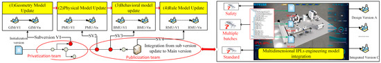
Figure 1.
Conceptual process of constructing IPLs in multiple dimensions.
RQ (1): How to effectively construct an IPLs experimental case with multiple knowledge evolutions to establish an architectural model that can achieve continuous version evolutions based on the AML standard engineering model construction method?
RQ (2): How to effectively construct a unified version management container for IPLs models on a decentralized platform to address the issue of multi-disciplinary knowledge privacy updates?
RQ (3): How to effectively construct an effective method to deal with conflicts in decentralized IPLs version solutions in combination with system architecture?
4. Methodology
As shown in Figure 2, the methodology of this article starts from the research object, research problem, further proposed solutions, and finally, targeted case testing. The key solutions are studied in the following three steps:
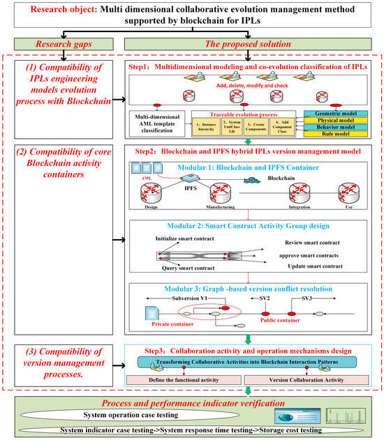
Figure 2.
Research methodology of this article.
(1) Based on the four-dimensional modeling method, a multi-dimensional collaborative work template model based on AML semantics is established and an abstract traceable blockchain configuration process is established based on AML modeling;
(2) A hybrid version management model of IPLs combining blockchain and the IPFS is proposed. Based on this, a collaborative management method based on a hybrid model of public and private versions is constructed. At the same time, around the management method, the innovative graph-based version batch conflict management mechanism and smart contract swarm management method are developed;
(3) Combining the perspective of the smart contract swarm and activity life cycle management, the detailed operation mechanism of the system architecture is designed and discussed.
4.1. Multi-Dimensional Modeling and Co-Evolution Classification of IPLs
As shown in Figure 3, AML-based modeling enables multi-team collaborative design and updates, forming the foundation for IPLs co-development.
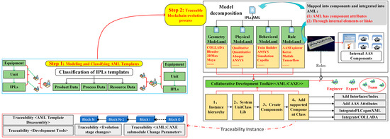
Figure 3.
Traceable AML model configuration process.
- Multi-dimensional AML template classification
Since the AML standard does not specify specific modeling details and can support expansion, this paper innovatively builds an IPLs modeling theory around four dimensions based on the literature [11,42,43]. In essence, it uses the relationship between the component development, mapping, and reference of the AML standard and the multi-dimensional modeling toolset to establish a workflow for defining instances, creating system units, creating components, and adding component types. In addition, the hierarchical structure of the IPLs is constructed based on the CAEX (Computer Aided Engineering Exchange) model in the IEC 62424 standard [12].
Geometric Model: For the description of geometric models, AML integrates the COLLADA data model to describe the geometry and kinematics of different objects through COLLADA 1.4.1 and 1.5.0 (ISO/PAS 17506:2012) [44]. Conventional collaborative tools include Blender, 3DMax, Maya, etc. In addition, for example, the Unity3D development component can parse FBX models that support the COLLADA specification and then compare and verify them with the 2D/3D drawings provided in the requirements document.
Physical Model: Physical parameters are usually related to specific structures, materials, environments, etc. Due to differences in physical properties, objectives, and conditions, it is difficult to use universal methods for consistency assessment as individual characteristics of physical entities need to be fully considered. In AML models, the description of physical models can generally be divided into “Qualitative parameters” and “Quantitative parameters” according to specified properties, which are often reflected in the COLLADA model. “Qualitative parameters” refer to clauses that have subjective feelings or judgments about a certain scope of application and design content that are interpreted and explained by humans. These clauses can only be evaluated by multiple experts participating in the project and then appear as normative guiding documents; “Quantitative parameters” refer to clauses that impose clear limitations on specific parts of structural design, such as the detailed dimensions of the cross-section of the machine tool base, the ratio of hoop reinforcement, and the rigidity of the main shaft. Commonly used development toolsets include Abaqus, ANSYS, Simulink, etc.
Behavior Model: The behavioral model is mainly used to evaluate the correctness of the behavioral sequence and response, which is reflected in the OpenPLC supported by AML [13]. For example, conventional logic modeling methods use sequence diagrams and state diagrams to represent behavioral characteristics. SysML “Sequence diagrams” are used to describe the interaction between the system and the environment and the mutual influence between the various parts of the system. SysML “State diagrams” are used to describe the state transitions of the system and the operations performed in response to various events. In addition, auxiliary designs, such as activity diagrams and use case diagrams, are also involved. Commonly used development toolsets include Capella, etc., which support SysML.
Rule Model: The rule model describes the universally recognized and followed laws and rules reflected in the IPLs. It also includes laws or rules in geometric, physical, and behavioral models, which can usually be obtained through accumulated experience and data mining. Following a rule-based model, the model has the ability to evaluate, develop, and reason. Considering the wide scope of the rule model, such as, scheduling rules, parameter optimization rules, production process control rules, etc., it is difficult to achieve modeling and evaluation in exactly the same way so it is often built using certain software features, such as the AAS that supports AML mapping to build corresponding sub-models for different rules. Common means include integrating MATLAB/TensorFlow, etc., through open-source tools, such as AASExplorer/OpenAAS, etc., to develop intelligent AAS rule models.
- 2.
- Traceable blockchain evolution process
The multi-dimensional model maps or integrates the components into AML based on the development tool. This is achieved through two created components that are integrated into AML through internal elements or links for traceability. Here, takes the rule model “RM.aml” as an example: ① Instance Hierarchy Definition: The instance hierarchy is the topological data of the storage model. For example, the case defines “i5BlocksInstanceHierarchy-RM”; the internal elements in the instance hierarchy can be instantiated through the system unit class and their access semantics can also be determined by referencing the role class. ② Create System Unit Class: AML formulates rules for defining system unit classes, allowing users to customize system unit classes based on rules; the system unit library includes levels, such as equipment, manufacturing units, or production lines, and is composed of reusable system component templates. ③ Create components: Components are used to further refine the specific functions of the unit class. In addition to being able to clearly define the functions of the components themselves, the organizational relationship can also add related models through interface references. Interface is used to describe the relationships between objects and their reference relationships to external information, which are stored in the interface class library. For example, the AAS, as a digital representation of intelligent devices, parses its common data, semantic system, model information, external data, and the connection relationship between them and then maps the AAS information model to the rules of the AML information model. For the interface relationship, refine the interface class into “InternalElements” or “SystemUnitClasses” or interface (or all interfaces); refine the “System Unit Class Lib” into “AssetAdministrationShell-SystemUnitClasses”. ④ Add the Component class: Components in production engineering are often developed around role classes. Based on the description of their permission characteristics, the component functions are further expanded (for example, in this design, the role is defined as the engineer responsible for equipment AAS modeling). For example, for the model collaboration process, according to the basic role class library definition in IEC 62714-1 [12,16], the AML function model can be effectively disassembled for design and updated by different teams.
Therefore, in general, it is feasible to disassemble IPLs from the multi-dimensional model, use the containers composed of blockchain and the IPFS to perfectly match the requirements of data block security and large file storage indexing, and further index them into the AML hierarchical relationship through existing development components or expanded development models.
4.2. Management Container Design
The integration of blockchain and the IPFS is the basis for the backend operation of IPLs versions. The innovation of this paper is that since the problem of switching between the main version and the batch version is often encountered in the process of version collaboration, and since different versions require the participation of different teams or individuals, this paper borrows the conceptual framework of blockchain, where each peer maintains an identical copy (or blockchain ledger) of only appended data to prevent the central administrator from manipulating the entire network. The IPFS (Interplanetary File System) uses a unique mechanism for CID (Content Identifier) file storage and indexing, which combines existing systems, such as distributed hash tables, BitTorrent, and self-certified file systems. The two work together to provide powerful technical advantages in handling record indexing and large and small batch data storage. For the privacy needs of a specific version, independent container space can be applied in a hybrid model. Some containers only require collaboration within a certain team while some containers require collaboration between different teams. In either case, the final release can be published to the public container (“transition channel”) through the signature authorization of the team leader.
4.2.1. Hybrid Management Model Design
As shown in Figure 4, this paper adopts a public and private container collaboration model. Specifically, in the scheme design of this article, a dedicated IPFS network involving version change initiators and approvers is constructed in each container and IPLs models waiting for updates and approvals are exchanged in this container. In addition, a special approval “transition channel” has been added between the IPFS large file storage space and distributed ledger containers. The purpose is to manage the process of updating branch-related versions through branch version number association and to provide dedicated containers for situations where certain process models require special permissions for approval before being published. Finally, the approved IPLs are transmitted to a shared container, which is another private IPFS network that involves information shared and confirmed by all authorized members. In the entire version management mechanism, each independent container consists of four parts, including a “version update process container”, a “version update approval container”, an “approved container”, and a consistent traceability blockchain ledger.
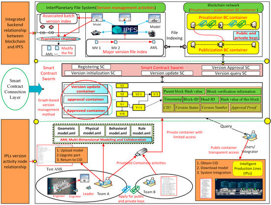
Figure 4.
Hybrid control model for IPLs based on blockchain and the IPFS.
- 1.
- IPLs version activity node relationship
Customers/system integrators release requirements for manufacturing IPLs systems through blockchain platforms and project members build (or revise) IPLs models in their local databases. Before sharing this updated model with all members, he/she will submit the IPLs model and model issues to the IPFS approval container for version change consent. Among them, unapproved model metadata (including the model CID and version number) can only be accessed by members in the approval layer (i.e., the dedicated IPFS network). If someone approves, the status change will be represented in the transaction and broadcasted to the blockchain by calling the smart contract. In this way, all project members will be informed that the IPLs model is currently, or has been, approved and can proceed to the next step of work.
The emergence of branch versions is because IPLs require service providers to update their respective functions (including algorithms) in a confidential manner. At this time, the system will automatically allocate a dedicated container to provide version collaborative updates between different service providers. Finally, in order to trace version history and consistency, their update records will still be synchronized in the blockchain network so the branch version container still includes the functions of submitting, updating, approving, and publishing IPLs versions in the branch container.
After receiving a version change request, the approver among project members will check the blockchain ledger of their team or collaborative team interactions and use the CID to download sub-models and issues in the IPFS. In addition to comparing the model with the delivery plan and agreed standards, the approver will also verify the consistency requirements and version accuracy of their model in the version review module. In actual projects, update steps often overlap and each update step involves approval work. In this case, the focus is on the IPLs consistency approval and version automation review.
The final approved version of the IPLs will be integrated again through the system integrator or users and the management process of this project will come to an end at this stage. If the previous branch version and approval process are correct, it will be publicly released and archived. It should also be noted that for abnormal versions (i.e., IPLs consistency review and version review studied in this article), the approver of each node will provide a detailed review list to relevant designers or teams for re-modification.
- 4.
- Backend relationship between the BC and IPFS
This paper analyzes the operational mechanism of the container model in two parts. In Figure 5 (1), private and public containers are represented, where the public container ensures the consistency and transparency of the main version, allowing any private team to access its progress and issues. The private container, on the other hand, handles version coordination and issue management within local or individual teams. While the two containers operate independently, they support collaborative interaction on specific branches. Additionally, Figure 5 (2) explains the operational mechanism from a workflow perspective.
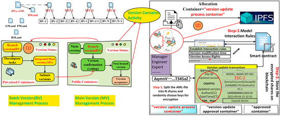
Figure 5.
Container allocation and workflow.
Step 1: In any allocated container, the IPLs model is divided into modules according to the AML generation rules and each module is assigned a unique hash fingerprint in the IPFS. The hash fingerprint is a unique string corresponding to the data block, similar to a human fingerprint, and engineers can locate the IPLs model data through this hash;
Step 2: Each allocated container uses a distributed hash table to record multiple node data. When searching or downloading an IPLs model, the hash fingerprint of the file is first calculated. This fingerprint, together with the Bit-Swap sharing network, can retrieve the IPLs model from other nodes;
Step 3: Teams, customers, or experts who meet the container permissions establish constraint rules through collaboration with each other. For example, these rules may include version parameter requirements, delivery time, problem frequency, and even penalty clauses for transactions.
For each container participating in the active node and container space, the “smart contract connection layer” acts as a transition layer between the application and the container kernel. On the one hand, it expands the blockchain alliance chain function. For example, Hyperledger Fabric is a mature blockchain platform with multi-functional design modules, such as distributed ledgers, alliance decision making, and smart contracts. On the other hand, it is compatible with the IPFS container architecture of the “main version” MV and the “branch version” BV. By integrating the “transition channel” function, it supports the update and approval of the branch version without affecting the main version management process. The overall solution is more suitable for system integration.
4.2.2. Graph-Based Version Conflict Resolution Design
In the context of public–private team transitions, multi-branch versions often create confusion. This paper explores version evolution process management from both serial and parallel perspectives. For traditional serial development workflows, once the IPLs model version evolution is initiated, collaborators receive the request, reach consensus, extract AML version information and model CID numbers encapsulated in the blockchain, and sequentially execute corresponding operations to update the IPLs model. The advantage of serial processing lies in ensuring version consistency but it suffers from inefficiency.
With the advancement of parallel engineering and other product development management techniques, project workflows have become increasingly parallelized, reducing development cycles. Consequently, collaborators involved in product IPLs modeling often perform parallel iterations of model evolution, which can lead to conflicts during the synchronization of modification information. Such conflicts, if occurring among multiple stakeholders, may result in mutual blame.
This paper proposes an innovative method to map version switching information into a graph model and establish a corresponding version conflict resolution and management model. The advantages and principles of graph model expression in multi-branch system management have been studied in detail in the literature [45,46] and this paper will not elaborate on them. In this paper, in the application of version conflict modeling, as shown in Figure 6, this article constructs the version conflict model as a directed Graph G = {N, E}, where N is the corresponding version node and E is the evolution information between each version node. The key parameter meanings of the corresponding nodes and edges are described in detail in Table 1 and can be adjusted according to the application scenarios in actual blocks.
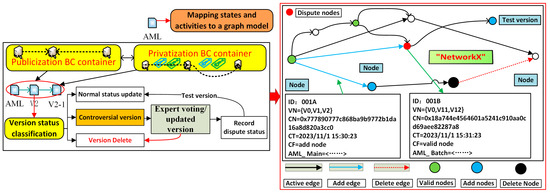
Figure 6.
Graph-based Version Conflict Mechanism.

Table 1.
Parameter definitions for nodes and edges.
The version conflict mechanism handling algorithm is shown in Appendix A, Table A1. This article constructs “DG = nx.DiGraph()” in Open-Source “NetworkX”. According to the above characteristics, the conflict processing and smart contract management process integration in the model synchronization process can be divided into three steps:
Step 1: Check for conflicting versions. When a certain operation node reads cached evolution operations in the IPFS and blockchain systems, it records the version node ID and CID value involving nodes and edges () and then parses the corresponding AML version through downloading;
Step 2: Branch processing of the problem. In the specific version update process, the administrator node (often the user or the leader of a team) sequentially executes the evolution operations to be synchronized in the block body and determines whether the relevant nodes and edges have been recorded in the previous step.
In this verification process, there are generally three situations: ① “Normal Operation”, which means checking the consistency of the model, confirming that this version is within a reasonable range, and then integrating the update information of this node and publishing it to the blockchain and IPFS systems, providing it to the next node for operation; ② “Deletion Operation”, which is mainly aimed at incorrect or abnormal versions (often by providing clear information about the problems of a certain sub-model after consistency verification). Version control administrators or experts will automatically or manually verify and provide feedback on abnormal versions of the previous model. In this case, it is important to note that if the node deletion operation involves locally modified nodes or edges, the problem ID and CID values should be recorded in the conflict list, and a “transition channel” should be set in IPFS. After complete deletion on the chain, they should retain the deletion record and publish the current version record again; ③ “Update Operation”, which is mainly aimed at the appearance of branch versions. At this time, the ID and CID values of the version are recorded in the conflict list and further version nodes and IPFS cache channels are created to represent the generation of new version branches;
Step 3: After resolving the version conflict, the model synchronization is completed again in the blockchain and IPFS systems. At this time, the responsible persons of both design teams and relevant technical experts will generally participate in the confirmation and, by attaching the “Approval Proof” to the “approved container”, the next batch of evolution will be promoted. Therefore, mapping the evolution process to the edges and nodes based on the graph model, and integrating tracking and process with multi-branch version management, can effectively overcome conflicts in parallel management.
4.3. System Operation Based on Smart Contract Group
In order to fully explain the evolution process based on the transaction model, as shown in Table 2, this paper configures and classifies the core activities of smart contracts based on different application roles in the project, from the perspective of activity abstraction and interface design, and defines the core activities of smart contracts as registering smart contracts (UR), initializing smart contracts (IC), updating smart contracts (UC), approving smart contracts (AC), and querying smart contracts (QC).
Table 2.
Example of smart contract swarm interface design.
On this basis, as shown in Figure 7, this paper associates interface activities by combining activity nodes and functional framework diagrams. Among them, the container is backed by blockchain and IPFS platforms, covering distributed ledgers, consensus technology, identity authentication, P2P peer-to-peer networks, Merkle Tree, etc; service nodes are specific activity nodes, including customers/demand parties, system integrators, designers (or teams), experts (or teams), etc.; the main version activity process based on AML revolves around the service node and initializes/updates/approves the model status of the main node, including major evolution activities, such as demand model, model decomposition, and integration model and; the sub-version activity process is further split from the main version activity process, corresponding to the further initialization/update/approval of the sub-activity node or group on the main version.
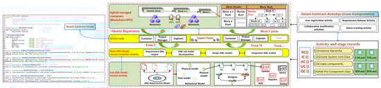
Figure 7.
Collaborative nodes and functional structure.
- 1.
- User registration activity
The user or team participating in the public–privatized container activity initiates a registration request, sends the registration information to the user node specified by the system, calls the UR () interface to trigger the user registration contract, uses the elliptic curve encryption algorithm to generate a unique public–private key pair for the user, and binds the registration information with the public–private key pair, that is, the private key = Map [username, user password]. Finally, the user node returns the public and private key pairs to the user. Among them, the user registration information is defined as follows: user = {name, pwd, id_ encryption, role}. Specifically, this represents the username, user password, user ID number encrypted, and role by the SHA1() function.
- 2.
- Requirement Release Activity
For registered customers, system integrators, or experts, the demand model is initialized, that is, the main version (the “Genesis” model). In this case experiment, further association graph model definition shows that in addition to the existing version information Vn, responsible person CC, and timestamp CT, the service node obtains the AML model CID number and downloads the instance information “AML_Main” extended by the entity through CF, which describes the project information, organization information, specific creator, etc., of the version in more detail. In addition to the main version chain, there are batch versions, which need to be associated with “AML_Main” through “AML_Batch”. For example, the definition of AML_ Main is as follows: AML_ Main = {GUID, project_ Name, per, org, action, T, mod_ Date, mod_ user, status}. Its contents are in this order: Global Unique Identifier (GUID), IPLs project name, creator information, creator organization information, AML Configuration Stage, timestamp, modification date, modified user, and usage status. In addition, for some projects that were not set during IPLs creation, some of the above content may be empty. On chain BV model initial information recording AML_ Init, the definition of AML_ Batch is as follows: AML_ Batch = {GUID, up_ name, version, main_ hash, uploader_ sign, root_ hash, T, uploader_ pub}, specifically including the GUID of the IPLs and the username of the uploader, version, main hash value, Uploader Private Key Signature, timestamp, and uploader public key.
- 3.
- Collaborative modification activities
When the collaborative reviewer of the IPLs version obtains the initialization version through identity verification, they initiate a request to submit the IPLs version modification information. Subsequently, they trigger the digital signature verification contract to verify whether the current user is an IPLs version preset modification user. If the verification is successful, they continue with the subsequent operations; otherwise, they reject the request and exit. Afterward, the QC () interface is called to trigger the query of the latest modification information of the AML version. This is completed by obtaining the AML version in the latest modification information record of the current chain and comparing it with the AML version before modification using the CID and IPFS. If there are any issues or restrictions on container access, they will be published in the transition channel designed in this article and controversial models will be modified and updated again. Here, the AC () transaction inherits all the metadata of the QC () transaction and adds new “Approval Status” and “Approval Proof” attributes. The approval status conveys the final decision of the approver while the approval certificate includes a membership certificate (the unique ID of a member in the blockchain) and a smart contract name to ensure the authoritative responsibility of the authorized personnel using the smart contract to publish this AC () transaction.
The description of the collaborative update process for the versions is the key design work of this stage, as shown in Figure 8. Taking the order of each version on the chain as an example, it illustrates the collaborative modification and submission process of multiple designers on the basis of the same initial version. ① Both DA and DB designers simultaneously obtain the initial IPLs for version “BN = 1” for modification. ② Designer DA first completes the creation and checks the latest version number in the current chain. The result is 1, which is compared to the local modified version. According to the defined update rules, the modified version is set to the pre-modified version plus 1 and then directly uploaded to the IPFS of the blockchain and IPLs, recorded as version V2. ③ Designer B then completed the creation and checked the latest version number of IPLs in the current chain. The result was “BN = 2”, which is the same as the total IPLs version before local modification plus 1. According to the revision rules, the latest modification information record on the current chain is returned and the completed versions are merged with the locally modified IPLs master version. The fused version is set to the local modified IPLs version plus 1 and uploaded to the blockchain and IPFS, marked as version V3 (AB). At this point, the designer DE obtains the IPLs for version V3 (AB) for creation. ④ Designer DE has completed the creation and checked the latest version number of IPLs in the current chain. The result is 2, which is smaller than adding 1 to the local modified IPLs version. According to the definition rules, the local modified IPLs version is set to add 1 to the local modified IPLs version and is directly uploaded to the blockchain and IPFS databases, recorded as version V4. ⑤ If a branch version appears at this time, which means that the current approver has objections to the consistency of the version, a new branch update version will be proposed. For example, if designer BVC wants to modify the V4 version, first check the latest version number in the current chain, and whether the result is “BN = 3”, which is larger than adding 1 to the local modified version. According to the defined rules, the latest modification information record on the current chain should be returned. At the same time, the fusion version should be set to the latest version on the current chain plus 1, and uploaded to the blockchain and IPFS databases, represented as version V5. ⑥ Finally, assuming that modifying the entire IPLs version update chain through branch versions will end, the user or system integrator will obtain the CID indexed by the blockchain in the IPFS through QC () and can also request access to the entire update record table through the consortium chain, which can support the traceability of problems that may arise in subsequent system integration or applications.

Figure 8.
Collaborative process for version changes.
The above is a detailed explanation of the multi-person collaborative modification and submission process of the IPLs version. The principles are the same in public and private containers, so we will not repeat them here.
- 4.
- Status tracking activity
The final key activity that needs to be explored is that users or system integrators can automatically identify blockchain activities and trace them through smart contract interfaces. In state tracking activities, it is supported for any activity node to view the current version of the process. The specific implementation method is to define multiple unique flag fields to trace their associated information, which is maintained uniformly through the AML_ Main document. For example, “ID” is the unique “key” of the AML model, which will be used throughout the entire design process and will not change. Project members can query the version change history in the blockchain through the ID number of the AML file. “Update version” is the new version number for updating AML models, and “Status” is used to indicate the applicability of the current version. For example, “Author” and “Approver” refer to stakeholders who act as initiators and should issue endorsements. “CID” is a hyperlink to access the corresponding AML in the IPFS. “Issue ID” and “Issue CID” have similar concepts to the AML models “ID” and “CID”, representing the change log files attached to the updated model.
5. Case Presentation and Discussion
Under experimental conditions, this paper simplifies the complexity of the system. Figure 9 (1) takes the AML-based IPLs as an example; each organization has one certificate authority service and three nodes, of which two nodes are Team 1 (indicating that two teams need to collaborate on the design) and one node is Team 2, to represent the design of the remaining links. The preset user or integrator publishes the IPLs construction requirements based on the AML description through the platform and assigns the sub-requirements to design team User1, design team User2, and AML system integration team User3. At the same time, within each team, there is an identity node (Team Leader) corresponding to the actual participation in the collaborative update of the version.
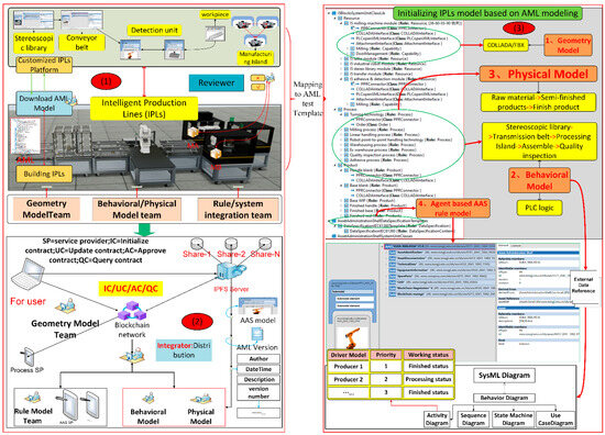
Figure 9.
Test cases and AML template mapping.
Figure 9 depicts the set-up of the Virtual Machine for the testing environment: ① Ubuntu 20.04 system and 8-core Intel (R) i7-1700HKCPU@2.40 GHz, 32 GB memory, used for running test networks. ② The Kafka experimental environment consists of three Zookeeper services and four Kafka services. ③ IPFS V1.8.0 and Hyperledger Fabric V1.4.9 are used to build distributed networks. ④ Smart contracts are programmed in the Go language and graph model algorithms are also integrated into the “NetworkX” environment. ⑤ A verification test platform is developed with Unity3D.
5.1. System Operation Testing
(1) AML Model and Component Initialization: This article assumes that the user or system integrator is the initiator of the IPLs version and the team leader initializes the requirements parameters for the final version. As shown in Figure 9 (3), this case simplifies the functional definitions of four modules. ① Geometry Model: Covers the planning and modeling of reusable system components according to the “I5Blocks” product line. ② Physical Model: Physical attributes are used to authenticate the identity information of the logical model of production factors in the logical space and restore some processing parameters of the actual production factors, mainly including type number, factor name, physical parameters and production and processing status, transmission speed, cutting force, and other data. ③ Behavioral Model: Behavior is an abstraction of actual production and processing resources. The logical model of the physical entity mainly describes the behavioral status of the corresponding elements in the production process through production behavior. ④ Rule Model: In this case, the rule model of the test is mapped to the AAS, which has a built-in algorithm for analyzing its own status. Specifically for AML sub model collaboration tools, as proposed in Section 4.1 of this article, the four steps are used to map the blockchain management process (creating instance hierarchy, setting unit classes, creating components, and modifying component properties); the geometric model is described using “lightweight FBX” (COLLADA model), the physical model is described using ANSYS, the behavioral model is described using SysML, and the AAS control processing rule model is implemented through a built-in algorithm library. For the initialization version, on the one hand, unified management based on an AML attribute description is used and, on the other hand, large files carried by attributes are added to the AML tag in the form of indexes.
(2) Graph-based version collaboration: System updates for IPLs versions are based on requirements and initialization versions. Specifically, the resource design team is responsible for designing the device AAS model. For any updated version of the AML Subversion Branch “V2-1”, the design node “A001Test” is the approver in the team. He/she downloaded the “MODEL-GAAS-001” model and used the UC () transaction to obtain the embedded CID publication file. “A001Test” checks the model quality and version consistency in the AML version. Then, he/she recognizes the latest version by calling the UC () smart contract to mark the version status and add approval proof to the AC () transaction. Successfully sharing the UC () transaction indicates that the “Behavior model-1.aml” version has been approved and can be used by other project specialties. After approval, UC () transactions not only provide proof of version changes and update version values in the blockchain but also publish approved models to the IPFS. Figure 10 (1,2) shows the activity results of version approval and updates in the IPFS and blockchain. The approver calls the smart contract to upgrade the version value to “V2-2” and synchronizes it to all ledger systems.
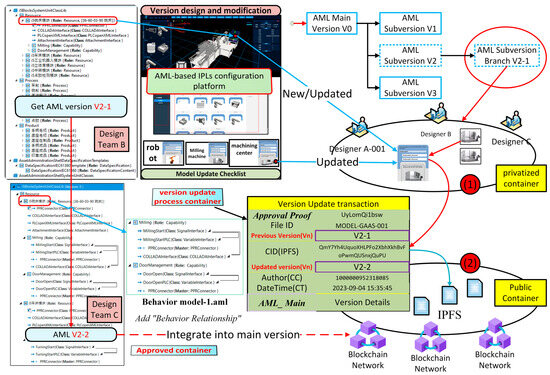
Figure 10.
Batch collaborative test case.
If there are any issues during the update process (i.e., the problematic version appears), the version approver will publish the current version to the IPFS network of the buffer channel. As shown in Figure 11 (1), this article will test the process in a digital twin platform, where reviewers will discuss the controversial version separately. In the case verification, a debugging system for the production line logic was established through Unity3D to simulate the SysML processing flow. Then, PLC (Programmable Logic Controller) debugging software was used to verify the key parameters mentioned above. In addition, simulation is conducted for geometry, physics, and rules, including verifying “lightweight FBX” by comparing CAD drawings, verifying fault types and corresponding fault descriptions by setting machining tasks, and verifying whether it supports interconnection between devices and negotiation mechanisms for tasks. This process requires repeated testing and verification and even the participation of relevant technical experts.
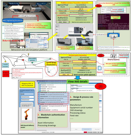
Figure 11.
Conflicting versions and visualizations are tested in private containers.
For handling version conflict events, such as version anomalies and conflicts in the “V2-1” version, it will be approved as a problematic version and further pushed to the IPFS network for multi-disciplinary and multi-expert coordination design and review. At the same time, members of other project teams can use the QC () smart contract to query existing transactions and related CIDs to access IPLs data. For version review and conflict resolution mechanisms, they are implemented based on the points and edges of the graph. While performing version verification, they can also update and delete conflicting versions through the graph network without disrupting the coherence of the versions. As shown in Figure 11 (2), a new branch version “V2-1-1” is displayed and all other access nodes can access its corresponding IPLs model, update parameters, negotiate interfaces between devices, and specific access activities are implemented through the API interface QC().
(3) Query and Visualization: Version query and visualization functions are an important part of the evolution process of IPLs versions. On the one hand, it can provide identity and asset tagging functions for designers and end-users of version collaborations. This means that access levels, application scopes, and functional limitations can be controlled through IPLs asset licensing. The core of this process lies in the uniqueness of the version and proof of all attributes, as shown in Appendix A, Table A2. The input parameters of the QC () smart contract will be queried through the unique identifier ID of the AML file; on the other hand, it can provide visual proof for both internal and inter-project teams. In the visual case design, this article assumes that after iterating through the version of the IPLs, as shown in Figure 11 (3), the IPLs system of the automated production line is finally configured. For specific versions of machine models, the latest blocks and corresponding IPFS pointers can be indexed to obtain and download the corresponding AAS model version, which includes basic AAS information, design, and process rule parameters.
5.2. System Indicator Testing
In addition to discussing the working mechanisms, the system’s performance metrics are tested and comprehensively evaluated to assess the impact of the blockchain network and IPFS network.
Response speed is an important indicator for evaluating the efficiency of smart contracts. As shown in Figure 12, this paper conducted 10 rounds of comparative tests. Overall, UC () requires the longest response time, with an average time of 53.3 ms. The fundamental reason is that not only do transaction records need to be updated but version updates also need to be considered. However, from the perspective of overall response speed, the other three types of smart contracts are all maintained within milliseconds (33–55 ms); in addition, from the comparison of public and private container data, since the number of concurrencies in private containers is higher than that in public, in the IC (), AC (), and UC () experiments, the values are obviously lower than that in public but the public QC () is higher than that in private. The reason is that in private concurrent operations, a large amount of verification data needs to be obtained from the public container but, overall, the response is maintained at the millisecond level, which can fully meet the needs of actual industrial applications.
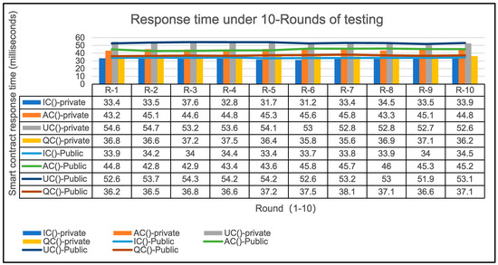
Figure 12.
Response time of smart contract swarm.
The IPFS response is a comparative test of IPLs models of different sizes under multiple concurrent nodes. This article designs, through qualitative comparison, thirteen types of access nodes (5, 10 15, 20, 25, 30, 35, 40, 45, 50, 55, 60, 65) and then conducts IPFS update tests on four types of lightweight models (2M, 4M, 6M, 8M, respectively). As shown in Figure 13, from the response results of the IPFS, as the size of the AML file increases, the overall response time gradually increases. In addition, as the number of peers increases, the computing load will also increase and it takes a certain amount of time to upload an AML file. Further comparison of the details shows that compared with traditional file disks, the overall response time of the system does not increase linearly. For example, for a 2M “test.aml” model, when 10 peers are concurrent, the response time is 0.55 s. However, when the size remains unchanged, when 50 peers are concurrent (that is, the number of concurrent instances has increased by five times), the response time is 0.84 s and the change has increased by about one-third, indicating that the IPFS has a higher overall reading efficiency as the number of nodes increases. Of course, from another perspective, if the size of “test.aml” decreases, its overall efficiency does not increase proportionally, indicating that as the marginal effect of storage decreases; when “test.aml” is too small, the proportion of initialization and network connection time will increase greatly, indicating that distributed file systems do not need multiple storage spaces like centralized systems but can be well stored according to the size of nodes. This also shows that the IPFS, as a distributed file system, is highly dependent on the number of nodes.
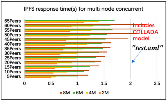
Figure 13.
Response time for multi-node concurrent issuance.
In addition, this article also tests storage cost based on transaction block models, with the aim of providing a reference for hard disk configuration cost. The testing of storage costs in this article includes blockchain ledger databases (“transaction data models”). For the transaction data model, we assume a transaction frequency of generating 1 block per minute for testing. This article only considers the maximum possible transaction data model (average 284 bytes) in the calculation process to measure the maximum storage cost. As shown in Table 3, we assume that every 10 transaction processes are packaged and added to the blockchain network for calculation. As shown in Figure 14, “Block Merkle tree” is generated through 20 “Hash number”. The principle is to select the SHA256 hash function, which can map content of any size to a 256-bit (32 B) [47] summary, and append the summary “Block Merkle tree” to the transaction block (fixed packaging to block test = summary × 20 Hash number = 640 B). Overall, each block is approximately 3595 bytes (3.6 KB) and the storage cost of the blockchain is 3.6 KB × 1 × 24 × 60 = 5184 KB ≈ 5.18 MB/day. This data amount is reasonable because currently, based on the on-site configuration of 50 GB of storage space, it can be used for more than 33 years in an ideal situation.
Table 3.
Block size for each transaction.
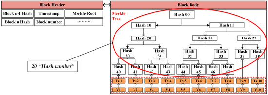
Figure 14.
Merkle tree for testing.
6. Conclusions
This study is not a universal system but rather utilizes the technological advantages of AML in building IPLs in multiple dimensions, focusing on the compatibility of blockchain-driven multi-dimensional model management based on AML mapping, the compatibility of hybrid containers in public–private management processes, and the compatibility between traditional centralized management models and smart contract management processes based on “transaction” models. Further exploration of blockchain-driven collaborative evolution methods was conducted and, based on this, research bottlenecks and specific solutions were proposed to guide system architecture design and case testing.
From the perspective of system operation mechanism, AML, as an effective tool for connecting multi-dimensional heterogeneous data models, effectively solves the uniformity of IPLs around heterogeneous components, such as DTs and the AAS. However, the transitional centralized management inevitably brings version consistency and security issues in the collaborative management process among multiple stakeholders. On the one hand, this article utilizes a hybrid decentralized architecture of blockchain and the IPFS to connect the reliability of IPLs stakeholders, incorporating the AML collaborative evolution process into a “transaction” based model, providing flexible recording and verification for version evolution in manufacturing systems, and greatly reducing disputes over version updates during collaboration. On the other hand, in the design of hybrid models, further consideration is given to the privacy protection characteristics of different stakeholders’ interoperability in public and private containers. Furthermore, by integrating graph-based version management models, conflict management during parallel version evolution can be effectively resolved under the premise of secure switching between public and private containers. From the perspective of key operational indicators of the system, although public containers require frequent interface interactions and have a higher response time than private containers in collaborative engineering, the overall response time of public and private containers can be maintained at the millisecond level, which is sufficient to meet practical engineering needs. In addition, this article designs an AML version of the “transaction model” to separate large model files and index data. With the increase in concurrency, its response time remains stable and, from the ideal disk operation calculation, it can effectively run for 33 years on a 50 GB disk and the overall indicators can well meet practical engineering applications.
In addition, there are still issues worth exploring in the design architecture of IPLs based on blockchain for multi-dimensional collaborative management methods. For example, in the collaborative process, some modules may need to consider more intellectual property, such as data space asset declaration. In addition, this article manually applied for public and private containers in the laboratory environment. In real application scenarios, it is necessary to comprehensively consider the impact of application costs on the overall system management.
Author Contributions
Conceptualization, K.D. and D.G.; methodology, K.D. and D.G.; software, K.D.; writing—original draft preparation, K.D.; writing—review and editing, D.G.; supervision, L.F. and D.G.; project administration, L.F. and D.G.; funding acquisition, L.F. and D.K. All authors have read and agreed to the published version of the manuscript.
Funding
This paper is supported by the National Key R&D Program of China (2022YFE0114100) and the International Exchange Program for Graduate Students, Tongji University (2023020019).
Institutional Review Board Statement
Not applicable.
Informed Consent Statement
Not applicable.
Data Availability Statement
The original contributions presented in this study are included in the article. Further inquiries can be directed to the corresponding authors.
Conflicts of Interest
The authors declare no conflicts of interest.
Appendix A
Table A1.
Graph-based version management process.
Table A1.
Graph-based version management process.
| Handling Version Conflict Algorithm Processes |
|---|
| Step 1: Input evolution list and synchronous evolution request sequence. Evolist, synlist Step 2: Traverse the evolution nodes and edges and record the corresponding IDs Procedure ConflietDetection(Evolist, synlist: Request[]) { var nodelist: hashset: for req: Evolist { if req.type = = node then nodeList.put(req.id) else edgeList.put(associatedNodes(req.id)); } Step 3: Check and modify the conflict list, including problematic nodes or edges Var conflictList, ConflictList:int []; For req:synList { Var nodeID: =(req.type==node)req.id: associatedNodes(req.id); Normal operation, perform version addition iteration if nodeList.contains(nodeID) { If req.operation==add Then Update operation ConflictList.update(nodeID); else Delete operation conflictList.delete(nodeID); } } Return to conflict list Return conflictList; |
Table A2.
Query algorithm process.
Table A2.
Query algorithm process.
| QC () Smart Contract Query Algorithm |
|---|
| Step 1: Smart contract checks legality of input member ID / file ID if the ID exists in the existing ledger If the Member ID verification validated Return file version properties else Return false Step 2: Smart contract queries and gets corresponding value in blockchain ledger Inquire results <- values of encryption key or design transactions End |
References
- Van der Linden, D.; Hadar, I.; Zamansky, A. What practitioners really want: Requirements for visual notations in conceptual modeling. Softw. Syst. Model 2019, 18, 1813–1831. [Google Scholar] [CrossRef]
- Pinquié, R.; Wang, H.; Noel, F. Human-Centric Co-Design of Model-Based System Architecture.33rd CIRP Design Conference. Procedia CIRP 2023, 119, 146–151. [Google Scholar] [CrossRef]
- Tao, F.; Zhang, M. Digital twin shop-floor: A new shop-floor paradigm towards smart manufacturing. IEEE Access 2017, 5, 20418–20427. [Google Scholar] [CrossRef]
- Liu, J.; Ji, Q.; Zhou, H.; Du, C.; Liu, X.; Li, M. A multi-dimensional evolution modeling method for digital twin process model. Robot. Comput. Integr. Manuf. 2024, 86, 102667. [Google Scholar] [CrossRef]
- Shi, J.; Liu, X.; Liu, T. Method of digital twin logic model oriented to production lines simulation. Comput. Integr. Manuf. Systems 2022, 28, 442–454. [Google Scholar] [CrossRef]
- Lu, Q.; Shen, X.; Zhou, J.; Li, M. MBD-Enhanced Asset Administration Shell for Generic Production Line Design. IEEE Trans. Syst. Man Cybern. Syst. 2024, 54, 5593–5605. [Google Scholar] [CrossRef]
- Winkler, D.; Ekaputra, F.; Biffl, S. AutomationML review support in multidisciplinary engineering environments. In Proceedings of the 2016 IEEE 21st International Conference on Emerging Technologies and Factory Automation, ETFA, Berlin, Germany, 6–9 September 2016; pp. 1–9. [Google Scholar]
- Lüder, A.; Schmidt, N.; Drath, R. Standardized Information Exchange Within Production System Engineering. In Multi-Disciplinary Engineering for Cyber-Physical Production Systems; Springer International Publishing: Berlin, Germany, 2017; pp. 235–257. [Google Scholar] [CrossRef]
- Lasi, H.; Fettke, P.; Kemper, H.G.; Feld, T.; Hoffmann, M. Industry 4.0. Bus. Inf. Syst. Eng. 2014, 6, 239–242. [Google Scholar] [CrossRef]
- Schmidt, N.; Lüder, A. Recovery planning method as end-of-life support for production systems. In Proceedings of the 2017 IEEE 15th International Conference on Industrial Informatics (INDIN), Emden, Germany, 24–26 July 2017; pp. 1103–1108. [Google Scholar] [CrossRef]
- Whitepaper AutomationML Part 6: AutomationML Component Document Identifier: WP Compo, V 1.1.0 State. October 2020. Available online: www.automationml.org (accessed on 11 March 2025).
- Automation ML Consortium. Application Recommendation: AAS Representation Document Identifier: AR AAS, V 1.0.0 State. November 2019. Available online: https://www.automationml.org/download-archive/ (accessed on 11 March 2025).
- Berardinelli, L.; Biffl, S.; Lüder, A.; Mätzler, E.; Mayerhofer, T.; Wimmer, M.; Wolny, S. Cross-disciplinary engineering with AutomationML and SysML. at-Automatisierungstechnik 2016, 64, 253–269. [Google Scholar] [CrossRef]
- Ferreira, P.; Anandan, P.D.; Pereira, I.; Hiwarkar, V.; Sayed, M.; Lohse, N.; Aguiar, S.; Gonçalves, G.; Goncalves, J.; Bottinger, F. Integrated Design Environment for Reusable Modular Assembly Systems. Assem. Autom. 2019, 39, 664–672. [Google Scholar] [CrossRef]
- Czvetkó, T.; Abonyi, J. Data sharing in Industry 4.0–AutomationML, B2MML and International Data Spaces-based solutions. J. Ind. Inf. Integr. 2023, 33, 100438. [Google Scholar] [CrossRef]
- Automation ML Consortium. Application Recommendation Provisioning for MES and ERP–Support for IEC 62264 and B2MML. Release Date: 19 January 2021. ID: AR-MES-ERP. Version: 2.0.0. Compatibility: Automation ML2.1(CAEX3.0). Available online: https://www.researchgate.net/publication/357457963_Application_Recommendation_Provisioning_for_MES_and_ERP_-_Support_for_IEC_62264_and_B2MML (accessed on 11 March 2025).
- Lehner, D.; Sint, S.; Vierhauser, M.; Narzt, W.; Wimmer, M. AML4DT: A model-driven framework for developing and maintaining digital twins with AutomationML. In Proceedings of the 2021 26th IEEE International Conference on Emerging Technologies and Factory Automation, ETFA, Vasteras, Sweden, 7–10 September 2021; pp. 1–8. [Google Scholar]
- Zhang, H.; Yan, Q.; Wen, Z. Information modeling for cyber-physical production system based on digital twin and AutomationML. Int. J. Adv. Manuf. Technol. 2020, 107, 1927–1945. [Google Scholar] [CrossRef]
- Lüder, A.; Hundt, L.; Keibel, A. Description of manufacturing processes using AutomationML. In Proceedings of the 2010 IEEE 15th Conference on Emerging Technologies & Factory Automation (ETFA 2010), Bilbao, Spain, 13–16 September 2010; pp. 1–8. [Google Scholar] [CrossRef]
- Strakošová, S.; Novák, P.; Kadera, P. Product-Oriented Product-Process-Resource Asset Network and its Representation in AutomationML for Asset Administration Shell. In Proceedings of the 2024 IEEE 29th International Conference on Emerging Technologies and Factory Automation (ETFA), Padova, Italy, 10–13 September 2024; pp. 1–8. [Google Scholar] [CrossRef]
- Winkler, D.; Nov, P.; Meixner, K.; Vysko, J.; Rinker, F.; Biffl, S. Product-process-resource asset networks as foundation for improving cpps engineering. In Proceedings of the 26th IEEE International Conference on Emerging Technologies and Factory Automation (ETFA 2021), Vasteras, Sweden, 7–10 September 2021; pp. 1–4. [Google Scholar]
- Ding, K.; Fan, L. AML-based web-twin visualization integration framework for DT-enabled and IIoT-driven Manufacturing system under I4.0 workshop. J. Manuf. Syst. 2022, 64, 479–496. [Google Scholar] [CrossRef]
- Backhaus, J.; Reinhart, G. Digital description of products, processes and resources for task-oriented programming of assembly systems. J. Intell. Manuf. 2017, 28, 1787–1800. [Google Scholar] [CrossRef]
- Bhosale, P.; Kastner, W.; Sauter, T. Comparative Analysis of AAS and AML as a Data Source for Integrated Risk Assessment in ICS. In Proceedings of the 2024 IEEE 29th International Conference on Emerging Technologies and Factory Automation (ETFA), Padova, Italy, 10–13 September 2024; pp. 1–4. [Google Scholar] [CrossRef]
- Jia, W.; Wang, W.; Zhang, Z. From simple digital twin to complex digital twin Part I: A novel modeling method for multi-scale and multi-scenario digital twin. Adv. Eng. Inform. 2022, 53, 101706. [Google Scholar] [CrossRef]
- Esser, S.; Vilgertshofer, S.; Borrmann, A. Graph-based version control for asynchronous BIM level 3 collaboration. In Proceedings of the EG-ICE Workshop on Intelligent, Computing in Engineering, Berlin, Germany, 30 June–2 July 2021; pp. 98–107. Available online: https://www.researchgate.net/publication/352835924 (accessed on 11 March 2025).
- Celik, Y.; Petri, I.; Barati, M. Blockchain supported BIM data provenance for construction projects. Comput. Ind. 2023, 144, 103768. [Google Scholar] [CrossRef]
- Bhawna; Parihar, V. Approaches and methodologies for distributed systems: Threats, challenges, and future directions. In Meta Heuristic Algorithms for Advanced Distributed Systems; John Wiley & Sons: Hoboken, NJ, USA, 2024; pp. 67–84. [Google Scholar] [CrossRef]
- López, A.; Casquero, O.; Estévez, E.; Armentia, A.; Orive, D.; Marcos, M. An industrial agent-based customizable platform for I4.0 manufacturing systems. Comput. Ind. 2023, 146, 103859. [Google Scholar] [CrossRef]
- Komesker, S.; Motsch, W.; Popper, J.; Sidorenko, A.; Wagner, A.; Ruskowski, M. Enabling a Multi-Agent System for Resilient Production Flow in Modular Production Systems. Procedia CIRP 2022, 107, 991–998. [Google Scholar] [CrossRef]
- Tang, H.; Li, D.; Wang, S.; Dong, Z. CASOA: An Architecture for Agent-Based Manufacturing System in the Context of Industry 4.0. IEEE Access 2017, 6, 12746–12754. [Google Scholar] [CrossRef]
- OvGU/IFAT–LIA, Universität Magdeburg. Specification Testbed “AAS Networked”, Proactive AAS-Interaction According to the VDI/VDE 2193; Universität Magdeburg: Magdeburg, Germany, 2019. [Google Scholar]
- Tao, X.; Liu, Y.; Wong, P.K.; Chen, K.; Das, M.; Cheng, J.C. Confidentiality-minded framework for blockchain-based BIM design collaboration. Autom. Constr. 2022, 136, 104172. [Google Scholar] [CrossRef]
- Zheng, R.; Jiang, J.; Hao, X.; Ren, W.; Xiong, F.; Ren, Y. bcBIM: A blockchain based big data model for BIM modification audit and provenance in mobile cloud. Math. Probl. Eng. 2019, 2019, 5349538. [Google Scholar] [CrossRef]
- Dietz, M.; Putz, B.; Pernul, G. A distributed ledger approach to digital twin secure data sharing. In Proceedings of the IFIP Annual Conference on Data and Applications Security and Privacy, Charleston, SC, USA, 15–17 July 2019, Springer: Berlin, Germany, 2019; pp. 281–300. [Google Scholar]
- Tao, F.; Zhang, Y.; Cheng, Y.; Ren, J.; Wang, D.; Qi, Q.; Li, P. Digital twin and blockchain enhanced smart manufacturing service collaboration and management. J. Manuf. Syst. 2022, 62, 903–914. [Google Scholar] [CrossRef]
- Menglei, Z.; Ling, T. Blockchain-based collaborative evolution method for digital twin ontology model of mechanical products. Comput. Integr. Manuf. Syst. 2023, 29, 1781. [Google Scholar] [CrossRef]
- Tao, X.; Das, M.; Liu, Y.; Cheng, J.C.P. Distributed common data environment using blockchain and Interplanetary File System for secure BIM-based collaborative design. Autom. Constr. 2021, 130, 103851. [Google Scholar] [CrossRef]
- Huang, S.; Wang, G.; Yan, Y.; Fang, X. Blockchain-based data management for digital twin of product. J. Manuf. Syst. 2020, 54, 361–371. [Google Scholar] [CrossRef]
- Tao, X.; Das, M.; Zheng, C.; Liu, Y.; Wong, P.K.; Xu, Y.; Liu, H.; Gong, X.; Cheng, J.C. Enhancing BIM security in emergency construction projects using lightweight blockchain-as-a-service. Autom. Constr. 2023, 150, 104846. [Google Scholar] [CrossRef]
- Zhang, H.; Qi, Q.; Tao, F. A consistency evaluation method for digital twin models. J. Manuf. Syst. 2022, 65, 158–168. [Google Scholar] [CrossRef]
- Tong, X.; Bao, J.; Tao, F. Co-evolutionary digital twins: A multidimensional dynamic approach to digital engineering. Adv. Eng. Inform. 2024, 61, 102554. [Google Scholar] [CrossRef]
- Liu, J.; Zhou, H.; Tian, G.; Liu, X.; Jing, X. Digital twin-based process reuses and evaluation approach for smart process planning. Int. J. Adv. Manuf. Technol. 2019, 100, 1619–1634. [Google Scholar] [CrossRef]
- Zhao, J.; Aghezzaf, E.H.; Cottyn, J. An AutomationML extension towards interoperability of 3D virtual commissioning software applications. Int. J. Comput. Integr. Manuf. 2023, 37, 1194–1213. [Google Scholar] [CrossRef]
- Esser, S.; Vilgertshofer, S.; Borrmann, A. Graph-based version control for asynchronous BIM collaboration. Adv. Eng. Inform. 2022, 53, 101664. [Google Scholar] [CrossRef]
- Esser, S.; Vilgertshofer, S.; Borrmann, A. Version control for asynchronous BIM collaboration: Model merging through graph analysis and transformation. Autom. Constr. 2023, 155, 105063. [Google Scholar] [CrossRef]
- Sheng, D.; Ding, L.; Zhong, B.; Love, P.E.D.; Luo, H.; Chen, J. Construction quality information management with blockchains. Autom. Constr. 2020, 120, 103373. [Google Scholar] [CrossRef]
Disclaimer/Publisher’s Note: The statements, opinions and data contained in all publications are solely those of the individual author(s) and contributor(s) and not of MDPI and/or the editor(s). MDPI and/or the editor(s) disclaim responsibility for any injury to people or property resulting from any ideas, methods, instructions or products referred to in the content. |
© 2025 by the authors. Licensee MDPI, Basel, Switzerland. This article is an open access article distributed under the terms and conditions of the Creative Commons Attribution (CC BY) license (https://creativecommons.org/licenses/by/4.0/).