Article

Mean Wave Drift Forces on a Barge-Type Floating Wind Turbine Platform with Moonpools

Department of Oceanic Architecture and Engineering, Nihon University, Funabashi, Chiba 274-8501, Japan
*
Author to whom correspondence should be addressed.
J. Mar. Sci. Eng. 2021, 9(7), 709; https://doi.org/10.3390/jmse9070709
Submission received: 1 June 2021 / Revised: 23 June 2021 / Accepted: 24 June 2021 / Published: 27 June 2021
(This article belongs to the Special Issue Offshore Wind Turbine Dynamic Analysis)

Abstract

:
Barge-type platforms with moonpools are a promising type of foundation for floating offshore wind turbines due to their good seakeeping performance. In this paper, the mean wave drift force on a barge-type vertical-axis floating wind turbine with multiple moonpools was investigated through physical model testing and numerical calculations using WAMIT. The focus was on the characteristics of mean drift load and its optimization potential. The present numerical results indicated that the application of moonpools was useful in reducing horizontal mean drift force at specific frequencies, and the reason was ascribed to the significant radiation effect of the resonant water oscillations in moonpools. The observed reduction effect on mean drift force was shown to be dependent on the viscous damping of moonpool resonance. The experimental results showed that the maximum response of the mean sway drift force was reduced by the gyroscopic effect of rotations of the vertical-axis wind turbine, and this reduction effect became stronger as the rotating speed of the wind turbine increased, but was weakened as wave amplitude increased. The comparisons between experimental data and potential flow predictions indicated that viscous effects should be taken into account to reasonably estimate the mean wave drift forces on barge-type floating wind turbines.

1. Introduction

Various concepts of floating offshore wind turbines (FOWTs) have been proposed over the past decades to utilize oceanic wind energy. As offshore floating systems, FOWTs may face harsh environments including strong winds and extreme waves. In addition to technical challenges, the high cost of energy hinders the commercialization of FOWTs. Hence, designs of floating wind turbines with not only good safety performance but also low production costs are particularly attractive to industries.
Regarding the support structure, barge-like floaters are relatively simple to design and construct. Jonkman and Buhl (2007) [1] and Robertson and Jonkman (2011) [2] analysed the load of a 5 MW floating wind turbine mounted on the ITI Energy Barge. Since barge-like platforms are susceptible to waves, many efforts have been made towards motion suppression/control by incorporating a tuned mass damper (TMD) [3,4,5] or a gyrostabilizer [6]. To avoid drifting, barge-type FOWTs are usually moored by catenary lines to the seafloor. Recently, Yang et al. (2021) [7] numerically analysed the transient behavior of a FOWT that suffered a sudden mooring line breakage.
Compared with conventional barge-type floating platforms, the application of a moonpool in the floating foundation has multifold advantages, including (i) improving seakeeping performance, (ii) reducing construction costs and (iii) increasing potential in multi-purpose applications, for instance, incorporating wave energy converters or fish cages [8]. An example is a 2 MW floating wind turbine developed by Ideol, named Floatgen, shown in Figure 1. As a demonstration project, the Floatgen wind turbine set many records in power production, despite experiencing challenging weather conditions with nearly 11 m high waves. Its excellent seakeeping performance is based on the “Damping Pool” [9], which is a moonpool in the floating platform.
Regarding the so-called damping pool, its “damping” effects result from water motions in the moonpool. Over the past two decades, extensive studies have been carried out on fluid resonances in moonpools [10,11,12,13]. An early theoretical study on the resonant modes in moonpools can be found in [14]. Through two-dimensional investigations, Faltinsen et al. (2007) [15] showed that the linear potential flow solution of piston-mode resonance amplitude in moonpools was significantly larger than experimental results. Subsequently Kristiansen and Faltinsen (2008, 2012) [16,17] showed that the overestimation by linear theory of resonant amplitude was mainly attributable to viscous damping due to flow separation at the moonpool inlets rather than the nonlinearities of free-surface boundary conditions. Consequently, CFD (Computational Fluid Dynamics) models and hybrid potential and viscous flow models have been developed to simulate moonpool resonance, with reasonable success [18,19]. In addition, modified potential flow models with an artificial viscous damping coefficient were also adopted to reasonably estimate the resonant amplitudes in moonpools while maintaining high computational efficiency [20,21].
Considering a barge-type FOWT with a moonpool, Beyer et al. (2015) [22], Borisade et al. (2016) [23] and Kosasih et al. (2019) [24] investigated the motion response characteristics through CFD simulations and physical experiments, respectively. Within the framework of potential flow theory, Ikoma et al. (2019) [25] analyzed the hydrodynamic coefficients and exciting forces of a barge with moonpool(s) through numerical calculations. Their results suggested that the hydrodynamic performance of a barge floater might be further improved by applying multiple moonpools rather than a single moonpool. Recently, considering a multi-moonpool platform installed with a vertical-axis wind turbine, Ikoma et al. (2021) [26] carried out investigations through 1:100 scale physical model tests and numerical analysis based on linear wave theory.
In addition to first-order hydrodynamic loads, mean (time-averaged) wave drift force as a component of second-order forces is usually of engineering significance for semi-submersible structures. Many studies have been carried out on mean drift forces and drift moments through calculations or experimental measurements [27,28,29,30]. For example, Ikoma et al. (2000) [31] studied the slowly varying wave drift forces on a very large floating structure in irregular waves using physical model tests. Newman (2004) [32] demonstrated the predicted second-order drift forces on different offshore structures using WAMIT. Zhang et al. (2020) [33] investigated the hydrodynamic responses of three types of semisubmersible FOWTs using second-order wave theory. Regarding theoretical and numerical calculations, the main approaches include (i) the near-field method, which is based on direct pressure integration over wet body surfaces [34], (ii) the far-field method, which is derived from the momentum conservation theorem [35,36] and (iii) the middle-field method, which involves the control-surface technique [37]. Numerical investigations of mean wave drift forces on barge-like structures can be found in [38,39]. Kashiwagi et al. (2005) [40] studied wave drift forces and moment on two vessels in a side-by-side arrangement. Chen et al. (2015) [41] calculated the horizontal and vertical drift forces on a cylindrical structure with a moonpool. To the authors’ knowledge, investigations on the influence of moonpool(s) on mean drift forces are still limited so far. This forms the main motivation of this study.
Compared with vertical-axis wind turbines, the research on horizontal-axis types has been an overwhelming majority of FOWT studies until now [42,43,44,45]. With the increasing diameter of wind turbines, maintenance work becomes difficult for horizontal-axis types of FOWTs due to the high position of the nacelle. In this respect, vertical-axis wind turbines are advantageous since the nacelle is generally placed at a low position. Another advantage of vertical-axis wind turbines is their natural insensitivity to wind direction. By contrast, an active yaw control system is usually required for horizontal-axis wind turbines to keep them aligned with the wind stream. For a rotating horizontal/vertical axis wind turbine, the axial inclination gives rise to gyroscopic effects and hence influences global motion responses [46,47]. Experimental and numerical investigations have been conducted on the effects of wind turbine rotations on the motion responses of FOWTs [48,49]; however, to the authors’ knowledge, the influence of wind turbine rotations on mean wave drift forces has hardly been investigated so far.
In this paper, the mean wave drift loads of a barge-type vertical-axis floating wind turbine with moonpools were studied. The primary purpose was to understand the characteristics of mean drift force and its optimization potential towards practical applications. Physical model tests were carried out in a wave basin, where varied rotating speeds of a vertical-axis wind turbine and different wave conditions were considered. The wave radiation-diffraction code WAMIT was used to conduct numerical analysis of mean drift forces and yaw drift moment. The remainder of the paper is structured as follows. The numerical analysis method is introduced in Section 2, followed by the descriptions of physical experiments in Section 3. In Section 4, experimental and numerical results are shown and discussed. Conclusions are drawn in Section 5.

2. Numerical Analysis Method

The numerical calculations of this study were carried out using the panel code WAMIT (Version 7.4), which solves wave radiation-diffraction problems in the frequency domain. A sketch of the calculation model and the definition of the coordinate system are illustrated in Figure 2. The origin o of the coordinate system was at the center of the barge-type floating platform on the still water level. The floater included four small rectangular moonpools (length is Lm and width is Wm) or one large moonpool (length is 2 Lm and width is 2 Wm). Regular waves were considered with the incidence angle defined as β.
To evaluate mean wave drift forces in this study, the far-field method was mainly used [36]. Horizontal drift forces and yaw drift moment were evaluated by momentum integration in the far field. Within the framework of potential flow theory, the formulations of mean horizontal drift force FDj (j = 1 or 2, denotes the degree of freedom) and yaw drift moment MZ can be found in [36]. Although mean drift forces and yaw moment are second-order wave loads, their values depend only on first-order velocity potential, which can be determined based on the Laplace equation and linearized boundary conditions.
The near-field method was also used in some computational cases for comparison analysis. Its formulations can be found in the WAMIT user manual [50] and hence are not shown here. The higher-order panel method was applied in the WAMIT calculations, and hence the source strength over each panel is not constant. Sufficient panels were used for the wet surfaces of the structure, which will be detailed in Section 4.1. Note that gyroscopic and aerodynamic effects due to turbine rotations were not modelled in the simulations. Linear springs with constant stiffness were used to model the mooring lines. There was no removal of irregular frequencies in the computations.

3. Physical Experiments

In our previous study [26], we presented a series of model tests conducted in the wave tank of Nihon University. A sketch of the experimental setup is shown in Figure 2, where a 2 MW vertical-axis wind turbine model in 1:100 scale was mounted on the center of a barge-type floating platform. The floating system was moored by four horizontal tethers to the linear springs connected with ring gauges. Four pulleys were used in the mooring system, where friction damping may have arisen and somewhat influenced the experimental results. This influence is difficult to eliminate in experimental measurements. The pre-tension of the springs was 2 N, and the spring stiffness was 23 N/m. The six degree-of-freedom motion responses of the floating system and associated mooring tether tensions were measured by the inertia sensor and ring gauges. The sample rate of the experimental data acquisition system was 100 Hz. FFT (Fast Fourier Transform) analysis was performed to obtain the zero-frequency component of mooring forces, and then mean drift forces were determined. No filtering treatment was conducted on the measured data. The main parameters of the floating foundation and wind turbine models can be found in Figure 3. The experimental variables are listed in Table 1, including the wave conditions and wind turbine conditions.
During the model tests, beam regular waves (i.e., β = 90°) of various periods were used. Two wave amplitudes were used, including Ai = 0.01 m and Ai = 0.02 m. The maximum wave steepness was estimated to be 0.07. Based on our experience, we predicted that the influence of wave reflections from tank sidewalls on experimental results would be rather weak for the present model. Note that wind was not modelled in the tests since no means of generating wind was available. An electrical motor was mounted on the floater to drive the wind turbine to rotate at designed velocities. The rotating speeds included 0, 40 rpm and 80 rpm. Two types of turbine blade were considered, corresponding to masses of Mb = 44 g and Mb = 154 g. Compared with the floating system, the relatively small variation in blade mass had little influence on the draft (the variation is approximately 0.001 m). By varying the rotating velocity and blade mass of the wind turbine, the gyroscopic effect resulting from wind turbine rotations was investigated. A detailed description of the model tests can be found in [26].

4. Results and Discussion

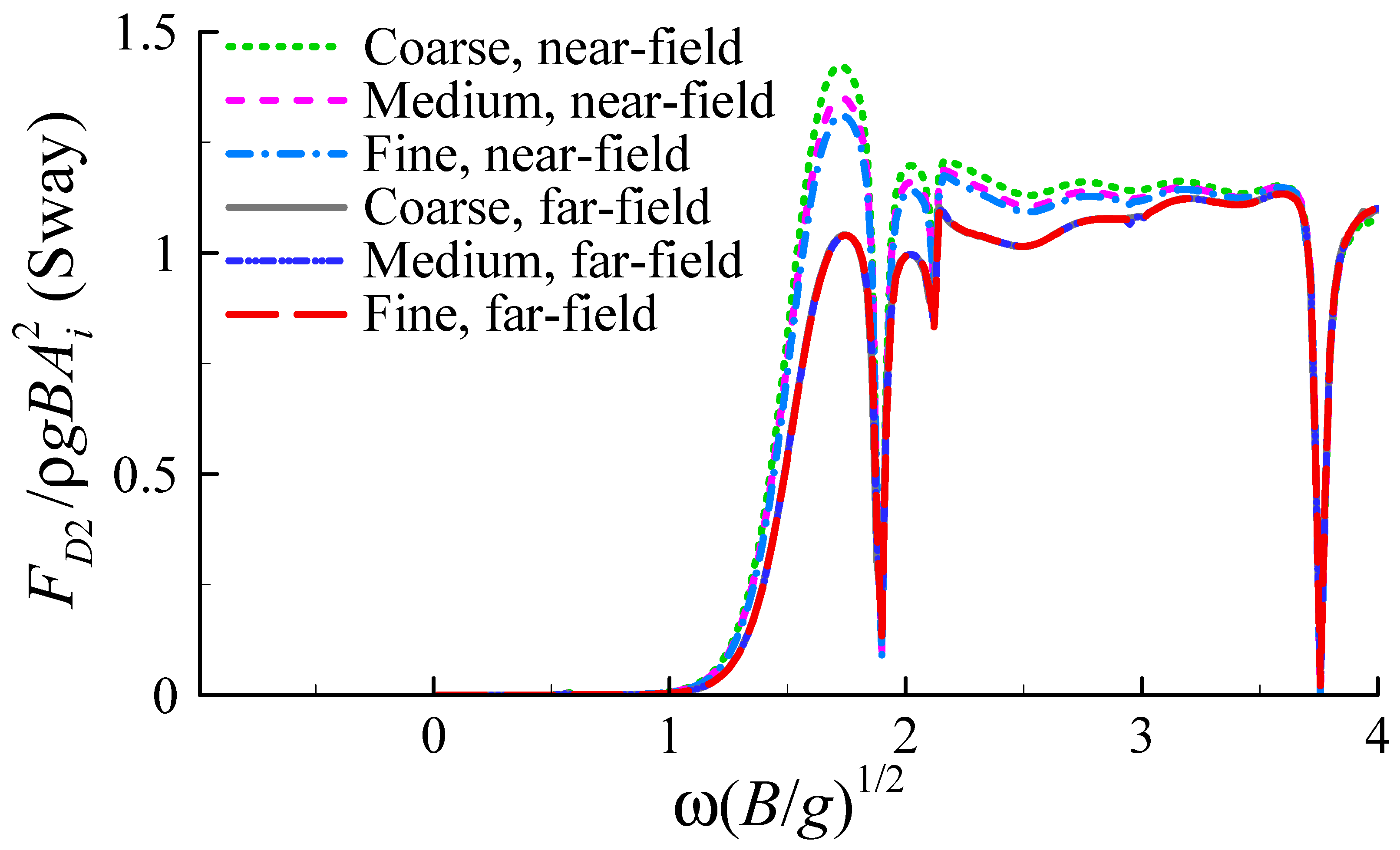
4.1. Mesh Convergence

A mesh convergence test was carried out before numerical analysis. Three types of computational meshes with different resolutions were used for the freely floating barge-type FOWT foundation with four moonpools. The geometric parameters of the barge and moonpools can be found in Figure 3. The calculated mean sway drift forces are shown in Figure 4, where ρ is the density of water and g is the gravitational acceleration. For the coarse, medium and fine meshes, the parameter “panel_size” of WAMIT was set to be 0.1, 0.05 and 0.025 in the computations, respectively, corresponding to the total number of computational panels of 144, 468 and 1332. Both the far-field method and the near-field approach were considered for comparison.
Regarding the far-field method, Figure 4 shows that the three types of meshes almost reached identical predictions. As for the near-field method, slight differences could be observed among the solutions of varied mesh densities. The predictions of the near-field method were larger than those of the far-field method, which is not surprising since estimations based on pressure integration are known to be of relatively lower accuracy due to the sharp edges of the barge foundation. For this reason, the far-field method and the medium mesh were mainly adopted in the following numerical analysis.

4.2. First-Order Motion Responses

To estimate the mean wave drift forces on the floating wind turbine (FWT) considered in the present experiments, the first-order motion responses of the FWT were calculated. The predictions were compared with experimental data from our previous study [26], as shown in Figure 5. Neither the viscous damping of the wave-induced motions nor the gyroscopic effects due to turbine rotations were considered in the calculations. The moment of inertia of a floating system for roll motions is difficult to determine, and may lead to inaccuracy of predictions for roll and sway responses according to our previous study [26]. Hence, in this study the moment of inertia of the FWT model was calibrated based on the measured data to obtained more reasonable predictions. Figure 5 shows that the first-order potential solutions in motion responses were generally in good agreement with the experimental results. The noticeable overestimations in the heave amplitude at ω(B/g)0.5 = 2.11 are attributable to the omission of viscous damping of the resonant water motions in the moonpools, which will be further discussed in Section 4.6. In Figure 5c1, it can be observed that the measured frequency of resonant sway response shifted to some extent as the rotating speed of the wind turbine was increased from 0 rpm to 40 (or 80) rpm. This variation in resonant frequency seems to be caused by experimental uncertainties rather than wind turbine rotations according to Figure 5a1. Regarding roll motions, the sharp spikes at ω(B/g)0.5 = 0.93 were clearly ascribed to the neglect of roll damping. The viscous effects on mean drift forces will be discussed in the next subsection.

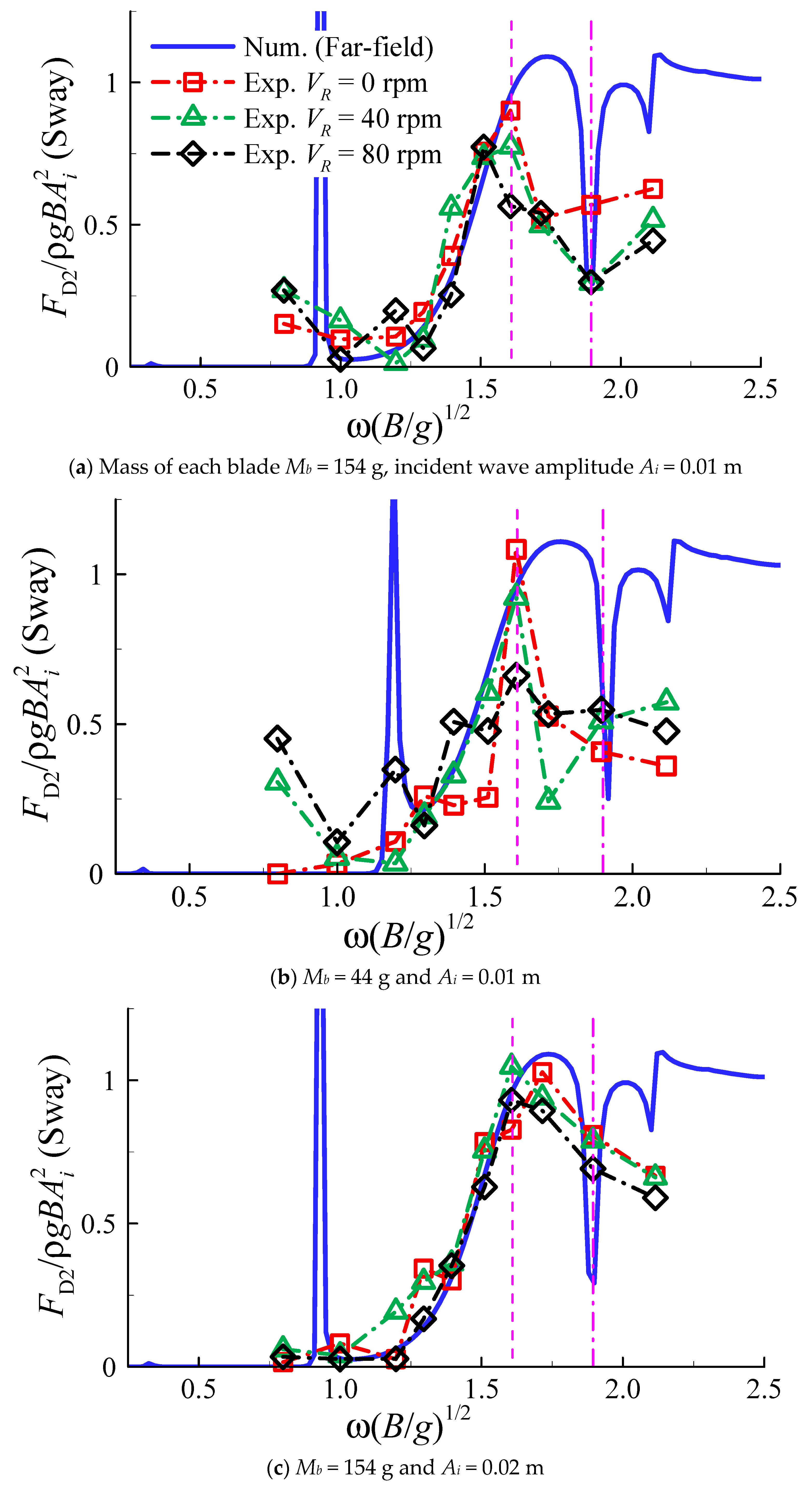
4.3. Influence of Turbine Rotations

As an extension to our previous study [26], in this study the experimental results of mean drift forces are presented and analyzed. Since the measured yaw motion of the floating system was rather small, the horizontal mooring force Fy in y-axis direction was estimated based on the measured tether tensions T1 ~ T4 by
F y = ( T 1 + T 2 T 3 T 4 ) sin 60 °
Figure 6 shows the time histories of the non-dimensional mooring force and the corresponding amplitude spectra from FFT analysis, where the three rotating speeds of VR = 0, 40 and 80 rpm are included, and Sb (=BL − 4 WmLm) is the area of the floating foundation surrounded by waterlines in the xy-plane. The period of incident waves in Figure 6 is T = 0.79 s (corresponding to ω(B/g)0.5 = 1.61). The mean sway drift force on the FWT model corresponds to half the amplitude at zero frequency of the response spectra. Figure 6 indicates that the mean sway drift force on the FWT model induced by beam waves could be even larger than the first-order wave force, and is therefore worthy of attention.
Figure 7 shows the experimental results of the mean sway drift force on the floating FWT model with four moonpools, where the WAMIT predictions using the far-field method are also included for comparison. Note that in the calculations, gyroscopic effects and viscous damping were not taken into account, and the mooring lines were considered as linear springs. Comparing Figure 7a,b, it can be seen that the numerical solutions were similar for Mb = 44 g and Mb = 154 g, since the variation in blade mass was fairly small compared with the total mass of the floating system. Figure 7 shows that the experimental and numerical results were generally in reasonable agreement, despite noticeable differences at some frequencies. The sharp spikes of numerical predictions are ascribed to the omission of viscous effects of motion responses on mean drift force.
It is known that higher rotating speed of a wind turbine will lead to a stronger gyroscopic effect, which plays a damping role in roll (and pitch) motions. The experimental results of Figure 7 indicate that wind turbine rotations influenced the mean sway drift force of the FWT model. At ω(B/g)0.5 = 1.61, the measured response of mean drift force attained the maximum value. As the rotating speed of the wind turbine increased, the maximum sway drift force was to some extent reduced. Comparing Figure 7a–c, as the incident wave amplitude was increased from 0.01 m to 0.02 m, the influence of wind turbine rotations on the mean drift force became weaker. This result suggests that the gyroscopic effect on mean sway drift force became relatively weak as the wave height was increased. At ω(B/g)0.5 = 1.90, the numerical solutions approached the response trough of the mean sway drift force. Indeed, this frequency corresponds to the water resonance in the moonpools (will be shown in Figure 9b). Compared with the numerical solutions, the experimental data suggested that the drop of mean drift force at ω(B/g)0.5 = 1.90 may not be significant. The reason for the difference between numerical and experimental results may result from the viscous effects of water resonance in the moonpools. This issue will be discussed in Section 4.6.

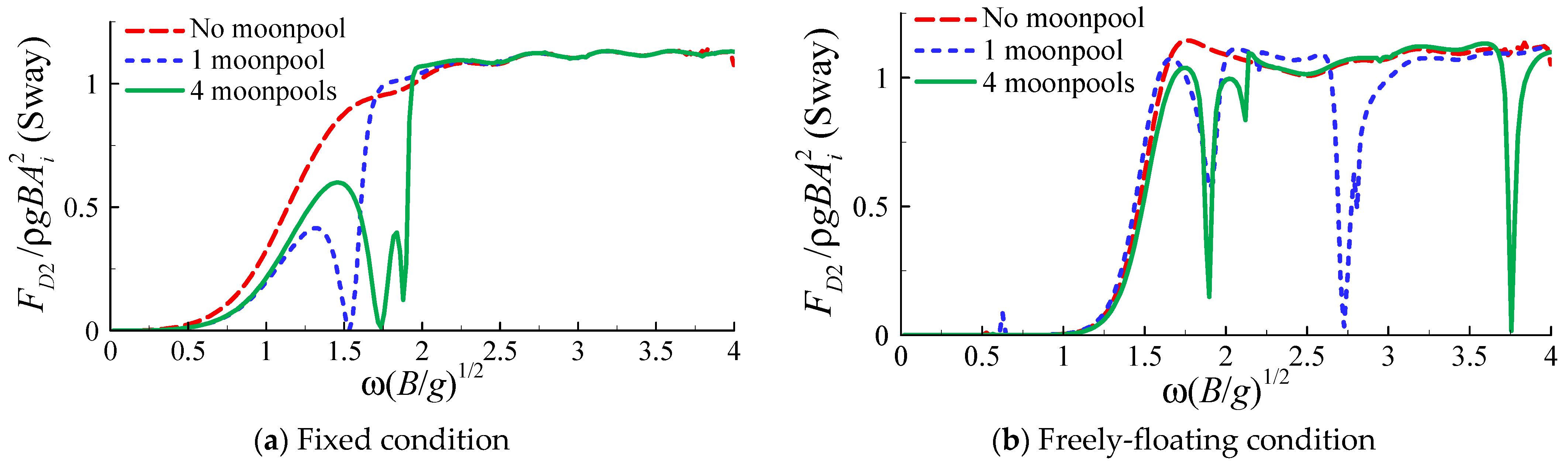
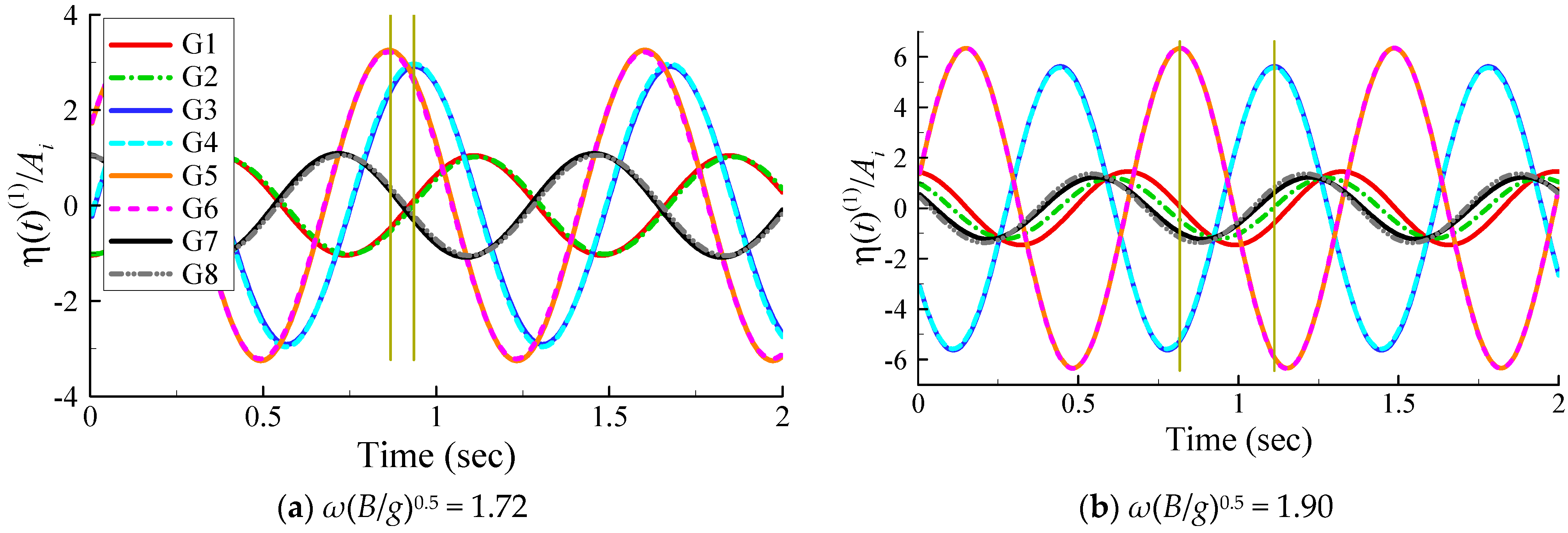
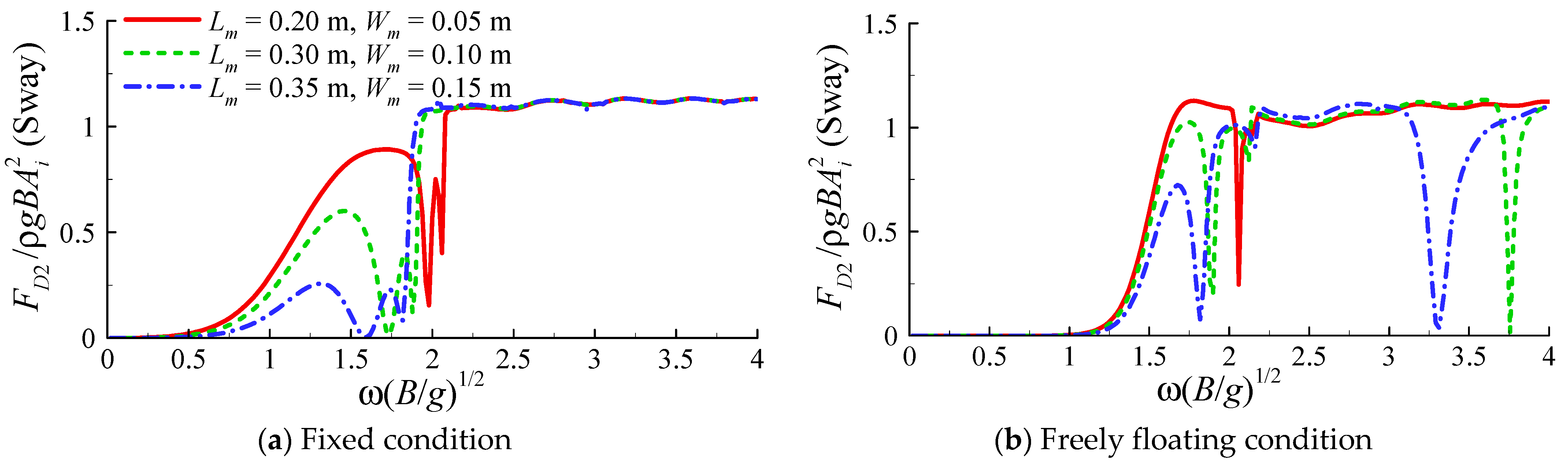
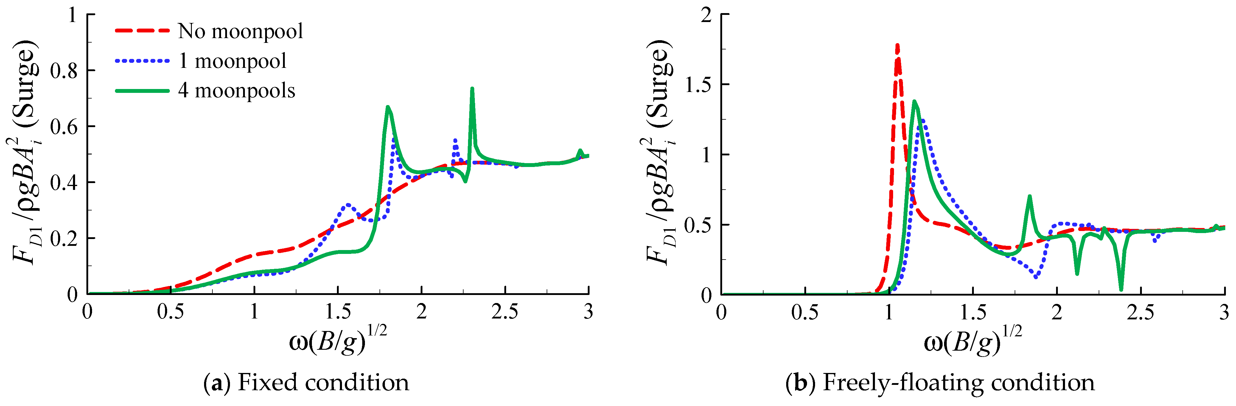
4.4. Influence of Moonpool(s)

Numerical analysis was subsequently carried out based on WAMIT calculations. Attention was first paid to the effects of moonpool(s) on the mean sway drift forces of the barge-type platform in beam waves (β = 90°). Figure 8 shows the numerical results, where three types of platforms were considered, including the barge-type foundation alone (See Figure 3 for its geometric parameters), the barge with a large single moonpool (area: 0.6 m × 0.2 m) and that with four small moonpools (area: 0.3 m × 0.1 m). Regarding the fixed-structure condition, Figure 8a demonstrates that the mean sway drift force could be substantially reduced by the application of moonpool(s) for the frequencies within approximately 1.3 < ω(B/g)0.5 < 2.0 (corresponding to the wave period range of 6.3–9.8 s in full scale). Compared with the one-moonpool case, the four-moonpool case corresponded to a wider frequency range of reduction in mean drift force. As for the free-floating condition, Figure 8b shows that the sway drift force was reduced by (water motions in the) moonpool(s) at some typical frequencies. Nevertheless, compared with the fixed condition, this reduction effect was not so pronounced, since the frequency range of the reduction in drift force was relatively narrow. Taking the four-moonpool case as an example, the sway drift force was seen to approach response troughs at ω(B/g)0.5 = 1.90 and ω(B/g)0.5 = 3.75, which correspond to the piston mode and sloshing mode fluid resonances in the moonpools, respectively. In general, Figure 8 indicates that the application of moonpools could be useful in reducing horizontal mean wave drift force.
To understand the physical mechanism of the moonpool’s effects on mean sway drift force, the wave responses near the barge and inside the moonpools were examined. For simplicity of analysis, a fixed barge with four moonpools in waves was used as the example, corresponding to the case in Figure 8a. Figure 9a shows a sketch of the positions of the numerical wave gauges; Figure 9b presents the calculated first-order free-surface responses at these positions. It can be seen that the wave responses at G3 and G4 were almost identical, as were those at G5 and G6. The water motion at G1 and G2 was similar, as well as that at G7 and G8 despite small differences at high frequencies. Regarding the water oscillations in moonpools, the two response peaks at ω(B/g)0.5 = 1.72 and ω(B/g)0.5 = 1.90 correspond to the first- and second-mode piston-type resonances (symmetric problem, the front and rear pools leading to two resonant modes and frequencies), respectively, whereas the sharp spikes at ω(B/g)0.5 = 2.95, 3.55 and 3.88 (corresponding wavelength: 0.29 m, 0.20 m and 0.17 m) were confirmed to be sloshing-mode resonances in moonpools. The observed two resonant frequencies in Figure 9b are consistent with the typical frequencies at which the mean sway drift force was much reduced as shown in Figure 8a, suggesting that the reduction in mean sway drift force was due to resonant water motions in the moonpools.
Furthermore, to explore the reason why the water resonance in moonpools could reduce horizontal mean drift force, the time histories of the wave responses at G1 ~ G8 were plotted based on the first-order frequency-domain solutions, as shown in Figure 10. Water motions at G1, G3, G5 and G7 were found to be almost in phase with their counterparts at G2, G4, G6 and G8, respectively. The oscillating amplitudes in the front and rear moonpools (defined in Figure 9a) were similarly much larger than those outside the moonpools. The water oscillations in the front and rear moonpools were close to in-phase motions at ω(B/g)0.5 = 1.72, and were close to anti-phase motions at ω(B/g)0.5 = 1.90. As for wave motion outside the moonpools, the most important finding from Figure 10 is that the wave run-up amplitudes at the windward and leeward sides of the barge were very close at the resonant frequencies, particularly at ω(B/g)0.5 = 1.72 (resonant frequency of the first mode). This result well explains the highly reduced mean sway drift forces at resonance shown in Figure 8a, where the mean sway drift force at ω(B/g)0.5 = 1.72 was observed to be almost zero. From a physical point of view, the phenomenon of similar run-ups at the wave incidence and transmission sides of the barge can be attributed to the significant radiation effect of moonpool resonance dominating the wave diffraction effect.
Considering the four-moonpool situation, Figure 11 shows the influence of the size of moonpools on the mean sway drift force, where Lm and Wm represent the length and width of each moonpool, respectively. Regarding the three cases in the figure, the corresponding ratio of the area of moonpools to that of the floating platform was 11.1%, 33.3% (present experimental setup) and 58.3%, respectively. Regarding the fixed condition, Figure 11a shows that the frequency range of reduction of mean drift force widened as moonpool area increased. For the case with Lm = 0.35 m and Wm = 0.15 m, the mean sway drift force was significantly reduced for ω(B/g)0.5 ≤ 1.8 (corresponding to T ≤ 7 s in full scale). For the free-floating condition, the reduction in frequency range also widened as the moonpools were enlarged, as shown in Figure 11b. Generally speaking, Figure 11 demonstrates that the observed reduction effect in mean drift force became stronger as moonpool area increased. Hence, we believe that favourable performance of the floating platform in respect to mean drift force could be achieved through geometric optimization.

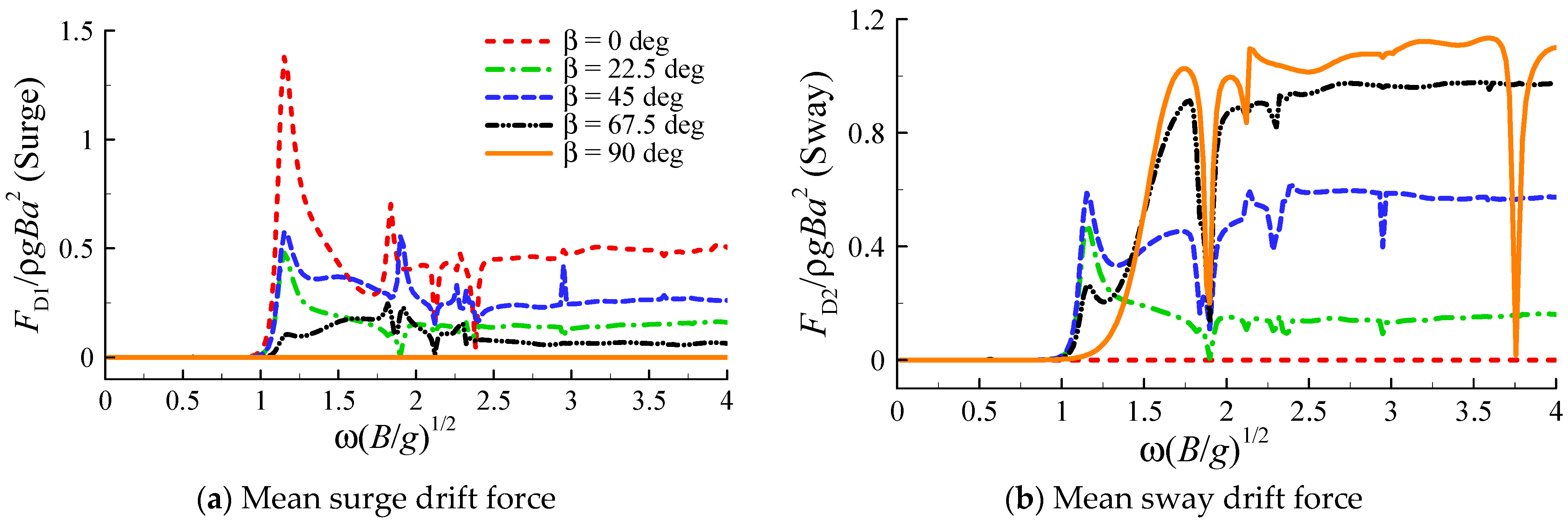
4.5. Influence of Wave Heading

Further attention was paid to the effects of wave direction on mean drift forces and yaw drift moment. Firstly, the head sea condition was considered, i.e., incidence angle β = 0°. Figure 12 shows the calculated mean surge drift forces, where three cases with and without moonpool(s) are included as before. The geometries of the barge and the moonpool(s) can be found in Figure 3. As shown in Figure 12a, under the fixed-floater condition, the mean surge drift force was slightly reduced by the moonpool(s) at the low-frequency range of ω(B/g)0.5 < 1.5, whereas it was amplified at some particular frequencies, for example, at ω(B/g)0.5 = 1.80 for the four-moonpool case. Regarding the free-floating condition, Figure 12b shows that the frequency of the maximum response of mean surge drift force shifted slightly due to the application of moonpool(s), and the maximum drift force value was to some extent reduced. In addition, the mean surge drift force may have been influenced by the moonpool(s) at certain frequencies, as suggested by Figure 12b.
Subsequently, the effects of wave heading on the surge and sway mean drift force were examined, as shown in Figure 13. It can be seen that, as the wave angle was increased from β = 0° to β = 90°, the surge drift force reduced gradually to zero, whereas the sway drift force increased substantially at a wide frequency range. At quartering sea condition (β = 45°), Figure 13 demonstrates the coupling response characteristics of surge and sway mean drift forces.
Figure 14 shows the calculated mean yaw drift moments on the barge with and without moonpool(s) at quartering waves (β = 45°). Regarding the fixed-floater condition, Figure 14a shows that the response peaks of mean yaw drift moment arose at certain frequencies with the application of moonpool(s). This result suggests that the mean drift yaw moment of the barge platform may be amplified by the water oscillations in moonpools. As for the free-floating condition, Figure 14b shows that the key frequencies corresponding to the large response peaks of the yaw drift moment shifted slightly as moonpool(s) were added. The maximum response value of mean yaw drift moment was influenced by water oscillations in the moonpool(s).

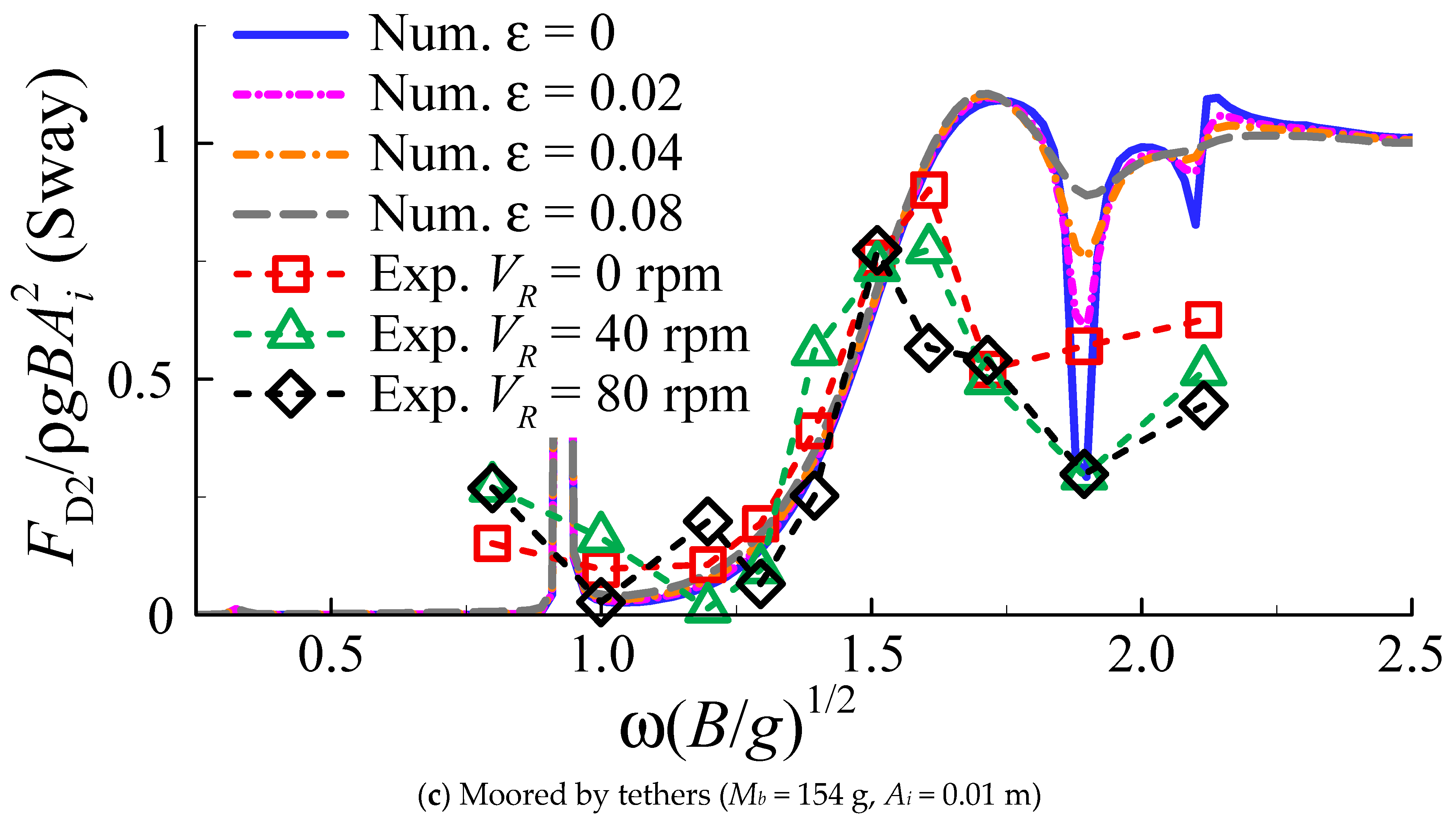
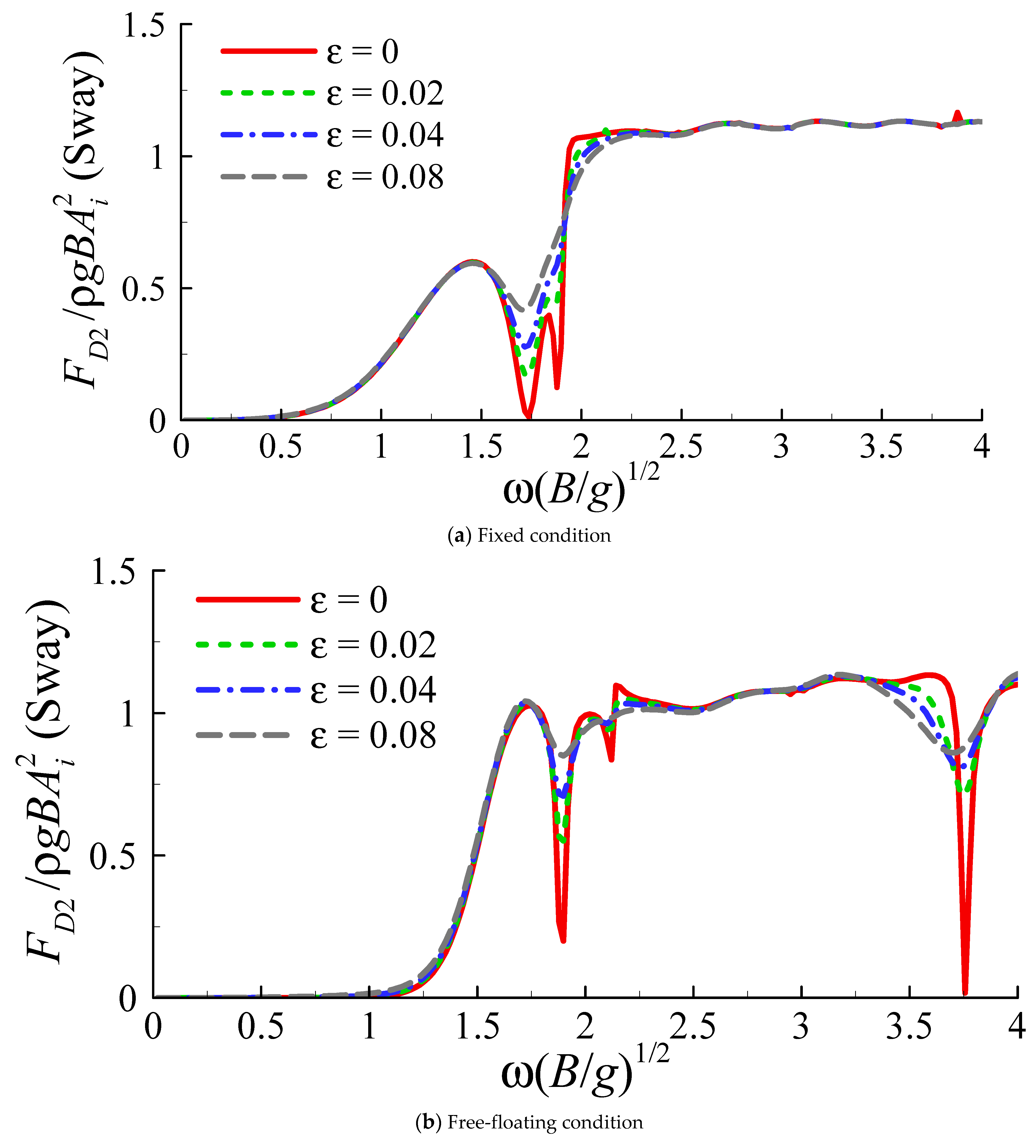
4.6. Influence of Viscous Damping of Moonpool Resonance

Finally, attention was paid to the influence of viscous damping of resonant water motions in moonpools on mean wave drift force. It is well known that flow separation at the moonpool inlets will lead to considerable viscous damping, which reduces the resonant responses in moonpools [16,17]. This damping is approximately proportional to the square of flow velocity (i.e., quadratic damping).
To take into account the viscous damping, damping lids were placed on the free surfaces in the moonpools in WAMIT calculations, as illustrated in Figure 15. The damping lids were set to be freely floating and impervious. The corresponding free-surface condition is written as
Δ ϕ ( 1 ) = i ε ω ϕ ( 1 ) z
where ε is the damping coefficient and ϕ(1) is first-order velocity potential. Although Equation (1) represents a linear damping, it can also take into account a quadratic damping using the equivalent linearization method.
In our previous study [51], it was shown that the introduction of free-surface damping reduced the first-order water resonance in moonpools and associated heave motion of the floater. In this study, four values of ε (including ε = 0, corresponding to no viscous damping) were used in the computations and the results of the predicted mean sway drift forces using the far-field method are shown in Figure 16. Regarding the fixed condition, Figure 16a shows that the reduction effects of the moonpools in mean sway drift force at the resonant frequencies (ω(B/g)0.5 = 1.72 and 1.90) gradually weakened with the increasing damping coefficient ε. As for the free-floating condition, a similar result can be observed in Figure 16b, where the amplitudes of the sharp spikes at the natural frequencies (ω(B/g)0.5 = 1.90, piston mode; ω(B/g)0.5 = 3.76, sloshing mode) were reduced with increasing ε. Figure 16c shows the variation of calculated mean drift force with ε under the experimental condition (moored by tethers). The result is similar to the calculation results of [52,53]. Indeed, the near-field method was also confirmed to lead to similar damping effects, though the results are not shown here. Generally speaking, Figure 16 indicates that the previously observed reduction effects of moonpool(s) on mean sway drift forces at key frequencies will be weakened if the viscous damping of the water oscillations in moonpools is considered.
The damping coefficient of fluid resonance in a moonpool is believed to be dependent on geometric and flow conditions [21]. In this study, the damping coefficient ranged from ε = 0 to ε = 0.08, to examine the viscous effects of moonpool resonance on mean drift force. To determine the exact value of ε, a reasonable method would be to conduct dedicated physical model tests or CFD simulations. This is outside the scope of the present study but will be an aspect of interest that we plan to investigate in our future works.

5. Conclusions

The characteristics of mean wave drift forces and yaw drift moment on a barge-type floating wind turbine platform with multiple moonpools were investigated through numerical analysis based on potential flow theory and 1:100 scaled physical model tests. The experimental results showed that the mean sway drift force was reduced by the gyroscopic effect of wind turbine rotations at specific frequencies, and this reduction effect became stronger as the rotating speed of the wind turbine increased, but was weakened when the incidental wave height increased. The mean drift forces as calculated by WAMIT were generally in reasonable agreement with the experimental measurements, except for overestimations at certain frequencies induced by the omission of viscous damping. This result indicates that viscous effects should be taken into account to reasonably estimate the mean wave drift forces on barge-type floating wind turbines.
The present numerical results demonstrated that the mean sway drift force on the barge-type platform was reduced by water oscillations in moonpools, and the reduction effect became stronger as moonpool area increased. This result reveals potential for substantially reducing mean drift forces through geometric optimizations. Compared with free-floating conditions, the reduction effect of moonpools in mean drift force was more pronounced under fixed-body conditions. By examining the wave run-ups around the barge-type platform and the wave responses inside the moonpools, the reduction in mean drift force was found to result from significant radiation effects of the large-amplitude fluid resonance in the moonpools. As viscous damping was taken into account in the calculations by introducing damping lids in the moonpools, the reduction effect on mean sway drift force was found to weaken with increased damping. This result indicates that the influence of moonpool (fluid) resonance on mean drift force is dependent on viscous damping.
In this study, the damping coefficient of the damping lids was chosen arbitrarily to examine the viscous effects of resonant oscillations in moonpools on mean sway drift force. To determine the exact value of the damping coefficient, dedicated physical model tests or CFD simulations are usually required. This is an aspect of interest that we plan to study in future.

Author Contributions

Conceptualization, T.I. and L.T.; methodology, T.I. and L.T.; validation, L.T.; formal analysis, L.T.; investigation, L.T.; writing—original draft preparation, L.T.; writing—review and editing, T.I. and L.T.; visualization, L.T.; supervision, T.I.; project administration, T.I., Y.A. and K.M.; funding acquisition, T.I., Y.A. and K.M. All authors have read and agreed to the published version of the manuscript.

Funding

This study is supported by the Nihon University College of Science and Technology Project for Research and the Open Research Fund of State Key Laboratory of Coastal and Offshore Engineering, Dalian University of Technology (No. LP2024).

Institutional Review Board Statement

Not applicable.

Informed Consent Statement

Not applicable.

Data Availability Statement

The data presented in this study are available on request from the corresponding author.

Conflicts of Interest

The authors declare no conflict of interest.

References

  1. Jonkman, J.M.; Buhl, M.L. Loads analysis of a floating offshore wind turbine using fully coupled simulation. In Proceedings of the Wind Power, Los Angeles, CA, USA, 3–6 June 2007; pp. 1–32. [Google Scholar]
  2. Robertson, A.N.; Jonkman, J.M. Loads analysis of several offshore floating wind turbine concepts. In Proceedings of the International Society of Offshore and Polar Engineers Conference, Maui, HI, USA, 19–24 June 2011. [Google Scholar]
  3. Hu, Y.; He, E. Active structural control of a floating wind turbine with a stroke-limited hybrid mass damper. J. Sound Vib. 2017, 410, 447–472. [Google Scholar] [CrossRef]
  4. Hu, Y.; Wang, J.; Chen, M.Z.Q.; Li, Z.; Sun, Y. Load mitigation for a barge-type floating offshore wind turbine via inerter-based passive structural control. Eng. Struct. 2018, 177, 198–209. [Google Scholar] [CrossRef]
  5. Yang, J.; He, E.M.; Hu, Y.Q. Dynamic modeling and vibration suppression for an offshore wind turbine with a tuned mass damper in floating platform. Appl. Ocean Res. 2019, 83, 21–29. [Google Scholar] [CrossRef]
  6. Palraj, M.; Rajamanickam, P. Motion control of a barge for offshore wind turbine (OWT) using gyrostabilizer. Ocean Eng. 2020, 209, 107500. [Google Scholar] [CrossRef]
  7. Yang, Y.; Bashir, M.; Li, C.; Wang, J. Investigation on mooring breakage effects of a 5 MW barge-type floating offshore wind turbine using F2A. Ocean Eng. 2021, 233, 108887. [Google Scholar] [CrossRef]
  8. Li, L.; Ruzzo, C.; Collu, M.; Gao, Y.; Failla, G.; Arena, F. Analysis of the coupled dynamic response of an offshore floating multi-purpose platform for the Blue Economy. Ocean Eng. 2020, 217, 107943. [Google Scholar] [CrossRef]
  9. Choisnet, T.; Favre, M.; Lyubimova, M.; Rogier, E. A robust concrete floating wind turbine foundation for worldwide applications. In Proceedings of the Grand Renewable Energy Proceedings, Tokyo, Japan, 27 July–1 August 2014. [Google Scholar]
  10. Maisondieu, C.; Ferrant, P. Evaluation of the 3D flow dynamics in a moonpool. In Proceedings of the 13th International Offshore and Polar Engineering Conference, Honolulu, HI, USA, 25–30 May 2003. [Google Scholar]
  11. Zhang, X.; Bandyk, P. On two-dimensional moonpool resonance for twin bodies in a two-layer fluid. Appl. Ocean Res. 2013, 40, 1–13. [Google Scholar] [CrossRef]
  12. Fredriksen, A.G.; Kristiansen, T.; Faltinsen, O.M. Wave-induced response of a floating two-dimensional body with a moonpool. Philos. Trans. R. Soc. A 2015, 373, 20140109. [Google Scholar] [CrossRef]
  13. Ravinthrakumar, S.; Kristiansen, T.; Molin, B.; Ommani, B. A two-dimensional numerical and experimental study of piston and sloshing resonance in moonpools with recess. J. Fluid Mech. 2019, 877, 142–166. [Google Scholar] [CrossRef]
  14. Molin, B. On the piston and sloshing modes in moonpools. J. Fluid Mech. 2001, 430, 27–50. [Google Scholar] [CrossRef]
  15. Faltinsen, O.M.; Rognebakke, O.F.; Timokha, A.N. Two-dimensional resonant piston-like sloshing in a moonpool. J. Fluid Mech. 2007, 575, 359–397. [Google Scholar] [CrossRef] [Green Version]
  16. Kristiansen, T.; Faltinsen, O.M. Application of a vortex tracking method to the piston-like behaviour in a semi-entrained vertical gap. Appl. Ocean Res. 2008, 30, 1–16. [Google Scholar] [CrossRef]
  17. Kristiansen, T.; Faltinsen, O.M. Gap resonance analyzed by a new domain—Decomposition method combining potential and viscous flow. Appl. Ocean Res. 2012, 34, 198–220. [Google Scholar] [CrossRef]
  18. Kristiansen, T.; Sauder, T.; Firoozkoohi, R. Validation of a hybrid code combining potential and viscous flow with application to 3D moonpool. In Proceedings of the 32nd International Conference on Ocean, Offshore and Arctic Engineering, Nantes, France, 9–14 June 2013. [Google Scholar]
  19. Jiang, S.C.; Sun, Z.; Feng, A.C.; Zhang, G.Y. On hydrodynamic behavior of fluid resonance in moonpool and its suppression by using various convex appendages. Ocean Eng. 2019, 192, 106552. [Google Scholar] [CrossRef]
  20. Faltinsen, O.M.; Timokha, A.N. On damping of two-dimensional piston-mode sloshing in a rectangular moonpool under forced heave motions. J. Fluid Mech. 2015, 772, 1–11. [Google Scholar] [CrossRef] [Green Version]
  21. Tan, L.; Lu, L.; Tang, G.Q.; Cheng, L.; Chen, X.B. A viscous damping model for piston mode resonance. J. Fluid Mech. 2019, 871, 510–533. [Google Scholar] [CrossRef]
  22. Beyer, F.; Choisnet, T.; Kretschmer, M.; Cheng, P.W. Coupled MBS-CFD simulation of the IDEOL floating offshore wind turbine foundation compared to wave tank model test data. In Proceedings of the 25th International Ocean and Polar Engineering Conference, Kona, HI, USA, 21–26 June 2015; pp. 367–374. [Google Scholar]
  23. Borisade, F.; Choisnet, T.; Cheng, P.W. Design study and full scale MBS-CFD simulation of the IDEOL floating offshore wind turbine foundation. J. Phys. Conf. Ser. 2016, 753, 092002. [Google Scholar] [CrossRef] [Green Version]
  24. Kosasih, K.M.A.; Niizato, H.; Okubo, S.; Mitani, S.; Suzuki, H. Wave tank experiment and coupled simulation analysis of barge-type offshore wind turbine. In Proceedings of the 29th International Offshore Polar Engineering Conference, Honolulu, HI, USA, 16–21 June 2019. [Google Scholar]
  25. Ikoma, T.; Nakamura, M.; Moritsu, S.; Aida, Y.; Masuda, K.; Eto, H. Effects of four moon pools on a floating system installed with twin-VAWTs. In Proceedings of the ASME 2019 2nd International Offshore Wind Technical Conference, St. Julian’s, Malta, 3–6 November 2019. IOWTC2019-7598. [Google Scholar]
  26. Ikoma, T.; Tan, L.; Moritsu, S.; Aida, Y.; Masuda, K. Motion characteristics of a barge-type floating vertical-axis wind turbine with moonpools. Ocean Eng. 2021, 230, 109006. [Google Scholar] [CrossRef]
  27. Konispoliatis, D.; Mavrakos, S. Mean drift forces on vertical cylindrical bodies placed in front of a breakwater. Fluids 2020, 5, 148. [Google Scholar] [CrossRef]
  28. He, G.H.; Zhang, Z.G.; Wang, W.; Wang, Z.K.; Jing, P.L. Near-trapping on a four-column structure and the reduction of wave drift forces using optimized method. J. Mar. Sci. Eng. 2020, 8, 174. [Google Scholar] [CrossRef] [Green Version]
  29. Cong, P.W.; Liu, Y.Y. Local Enhancements of the mean drift wave force on a vertical column shielded by an exterior thin porous shell. J. Mar. Sci. Eng. 2020, 8, 349. [Google Scholar] [CrossRef]
  30. Seo, M.G.; Ha, Y.J.; Nam, B.W.; Kim, Y. Experimental and numerical analysis of wave drift force on KVLCC2 moving in oblique waves. J. Mar. Sci. Eng. 2021, 9, 136. [Google Scholar] [CrossRef]
  31. Ikoma, T.; Maeda, H.; Rheem, C.K. Slowly varying wave drifting force on a very large floating structure in short crested waves. In Proceedings of the OCEANS 2000 MTS/IEEE Conference and Exhibition, Providence, RI, USA, 11–14 September 2000; Volume 1, pp. 533–539. [Google Scholar]
  32. Newman, J.N. Progress in wave load computations on offshore structures. In Proceedings of the 23rd International Conference on Offshore Mechanics and Arctic Engineering, Vancouver, BC, Canada, 20–25 June 2004. [Google Scholar]
  33. Zhang, L.; Shi, W.; Karimirad, M.; Michailides, C.; Jiang, Z. Second-order hydrodynamic effects on the response of three semisubmersible floating offshore wind turbines. Ocean Eng. 2020, 207, 107371. [Google Scholar] [CrossRef]
  34. Pinkster, J.A.; Oortmerssen, G. Computation of the first- and second- order wave forces on oscillating bodies in regular waves. In Proceedings of the International Conference on Numerical Ship Hydrodynamics, Berkeley, CA, USA, 19–21 September 1977. [Google Scholar]
  35. Maruo, H. The drift of a body floating in waves. J. Ship Res. 1960, 4, 1–10. [Google Scholar]
  36. Newman, J.N. The drift force and moment on ships in waves. J. Ship Res. 1967, 11, 51–60. [Google Scholar] [CrossRef]
  37. Chen, X.B. Middle-field formulation for the computation of wave-drift loads. J. Eng. Math. 2007, 59, 61–82. [Google Scholar] [CrossRef]
  38. Choi, Y.R.; Hong, S.Y.; Choi, H.S. An analysis of second-order wave forces on floating bodies by using a higher-order boundary element method. Ocean Eng. 2000, 28, 117–138. [Google Scholar] [CrossRef]
  39. Park, D.M.; Kim, J.H.; Kim, Y. Numerical study of mean drift force on stationary flexible barge. J. Fluids Struct. 2017, 74, 445–468. [Google Scholar] [CrossRef]
  40. Kashiwagi, M.; Endo, K.; Yamaguchi, H. Wave drift forces and moments on two ships arranged side by side in waves. Ocean Eng. 2005, 32, 529–555. [Google Scholar] [CrossRef]
  41. Chen, X.B.; Liu, H.X.; Duan, W.Y. Semi-analytical solutions to wave diffraction of cylindrical structures with a moonpool with a restricted entrance. J. Eng. Math. 2015, 90, 51–66. [Google Scholar] [CrossRef]
  42. Collu, M.; Brennan, F.P.; Patel, M.H. Conceptual design of a floating support structure for an offshore vertical axis wind turbine: The lessons learnt. Ships Offshore Struct. 2014, 9, 3–21. [Google Scholar] [CrossRef]
  43. Borg, M.; Shires, A.; Collu, M. Offshore floating vertical axis wind turbines, dynamics modelling state of the art. part I: Aerodynamics. Renew. Sustain. Energy Rev. 2014, 39, 1214–1225. [Google Scholar] [CrossRef] [Green Version]
  44. Paulsen, U.S.; Borg, M.; Madsen, H.A.; Pedersen, T.F.; Hattel, J.; Ritchie, E.; Ferreira, C.S.; Svendsen, H.G.; Berthelsen, P.A.; Smadja, C. Outcomes of the DeepWind conceptual design. Energy Procedia 2015, 80, 329–341. [Google Scholar] [CrossRef] [Green Version]
  45. Liu, Y.; Hu, C.; Sueyoshi, M.; Yoshida, S.; Iwashita, H.; Kashiwagi, M. Motion response characteristics of a Kyushu-University semi-submersible Floating Wind Turbine with trussed slender structures: Experiment vs. numerical simulation. Ocean Eng. 2021, 232, 109078. [Google Scholar] [CrossRef]
  46. Blusseau, P.; Patel, M.H. Gyroscopic effects on a large vertical axis wind turbine mounted on a floating structure. Renew. Energy 2012, 46, 31–42. [Google Scholar] [CrossRef]
  47. Mostafa, N.; Murai, M.; Nishimura, R.; Fujita, O.; Nihei, Y. Study of motion of spar-type floating wind turbines in waves with effect of gyro moment at inclination. J. Nav. Archit. Mar. Eng. 2012, 9, 67–79. [Google Scholar] [CrossRef] [Green Version]
  48. Murai, M.; Nishimura, R. A study on an experiment of behavior of a SPAR type offshore wind turbine considering rotation of wind turbine blades. In Proceedings of the OCEANS’10 IEEE Sydney, Sydney, Australia, 24–27 May 2010; pp. 1–8. [Google Scholar]
  49. Nihei, Y.; Matsuura, M.; Fujioka, H.; Suzuki, H. An approach for the optimum design of TLP type offshore wind turbines. In Proceedings of the ASME 2011 30th International Conference on Ocean, Offshore and Arctic Engineering, Rotterdam, The Netherlands, 19–24 June 2011. OMAE2011-50258. [Google Scholar]
  50. Lee, C.; Newman, J. Wamit User Manual, Version 7.4; Wamit, Inc.: Chestnut Hill, MA, USA, 2021. [Google Scholar]
  51. Tan, L.; Ikoma, T.; Fujishima, K.; Aida, Y.; Masuda, K. Investigation of motions of a floating wind turbine foundation with multiple moonpools. In Proceedings of the Fourteenth (2020) ISOPE Pacific-Asia Offshore Mechanics Symposium, Dalian, China, 22–25 November 2020. [Google Scholar]
  52. Michima, P.; Kawabe, H. Preliminary chart of drill ship operability considering moon-pool sloshing effects. In Proceedings of the 24th International Ocean and Polar Engineering Conference, Busan, Korea, 15–20 June 2014. [Google Scholar]
  53. Vada, T.; Pan, Z.Y. On the handling of moonpool resonances by Green’s function methods. In Proceedings of the ASME 2018 37th International Conference on Ocean, Offshore and Arctic Engineering, Madrid, Spain, 17–22 June 2018. [Google Scholar]
Figure 1. Floatgen, a 2 MW floating wind turbine demonstrator in France (courtesy of Ideol).
Jmse 09 00709 g001
Figure 2. Sketch of calculation model and definition of coordinate system.
Jmse 09 00709 g002
Figure 3. Sketch of the setup of physical model tests. (Adapted from Ikoma et al. (2021) [26]).
Jmse 09 00709 g003
Figure 4. Comparison of calculated mean sway drift forces on the freely floating barge with four moonpools using the near-field and far-field methods with different mesh resolutions.
Jmse 09 00709 g004
Figure 5. First-order motion responses of the vertical-axis floating wind turbine with four moonpools in beam waves. (a1a3) Mb = 154 g and Ai = 0.01 m; (b1b3) Mb = 44 g and Ai = 0.01 m; (c1c3) Mb = 154 g and Ai = 0.02 m.
Jmse 09 00709 g005
Figure 6. (a) Non-dimensional time histories of the mooring force in the y-axis direction at different rotating speeds of the wind turbine (T = 0.79 s, Mb = 154 g and Ai = 0.01 m); (bd) the corresponding amplitude spectra.
Jmse 09 00709 g006
Figure 7. Measured and calculated mean sway drift forces on the floating wind turbine with four moonpools in beam waves (VR is the rotating speed of wind turbine).
Jmse 09 00709 g007
Figure 8. Calculated mean sway drift forces on a barge with/without moonpool(s) in beam waves.
Jmse 09 00709 g008
Figure 9. Calculated first-order wave responses inside/outside the moonpools of a fixed barge in beam waves.
Jmse 09 00709 g009
Figure 10. Time histories of the free-surface responses at G1 ~ G8 based on linear frequency-domain solutions.
Jmse 09 00709 g010
Figure 11. Influence of the size of moonpools on mean sway drift force of a barge in beam waves.
Jmse 09 00709 g011
Figure 12. Calculated mean surge drift forces on a barge with/without moonpool(s) in head waves (wave angle β = 0°).
Jmse 09 00709 g012
Figure 13. Influence of incident wave angle on horizontal mean drift forces on a freely floating barge with four moonpools.
Jmse 09 00709 g013
Figure 14. Calculated mean yaw drift moments on a barge with/without moonpool(s) in quartering waves (β = 45°).
Jmse 09 00709 g014
Figure 15. Illustration of the damping lids placed on water surfaces in moonpools.
Jmse 09 00709 g015
Figure 16. Influence of viscous damping of water oscillations in moonpools on mean sway drift force of a barge in beam waves. The results are calculated using WAMIT using the far-field method. (ε is the damping coefficient).
Jmse 09 00709 g016aJmse 09 00709 g016b
Table 1. Experimental variables.
ParameterValue
Incident wave period (T)0.6 s ~ 1.6 s
Incident wave amplitude (Ai)0.01 m or 0.02 m
Mass of each blade (Mb)44 g or 154 g
Rotating velocity of turbine (VR)0, 40 rpm or 80 rpm
Publisher’s Note: MDPI stays neutral with regard to jurisdictional claims in published maps and institutional affiliations.

