Author Contributions
Conceptualization, C.L., P.Z. and H.D.; Methodology, C.L. and J.R.; Software, J.R. and C.L.; Validation, C.L., P.Z. and H.D.; Formal Analysis, J.R. and C.L.; Writing—Original Draft Preparation, J.R., C.L. and K.W.; Writing—Review and Editing, C.L., J.R., K.W.; Supervision, C.L., P.Z. and H.D.; Project Administration, C.L., H.D. and P.Z.; Funding Acquisition, C.L., H.D. and P.Z. All authors have read and agreed to the published version of the manuscript.
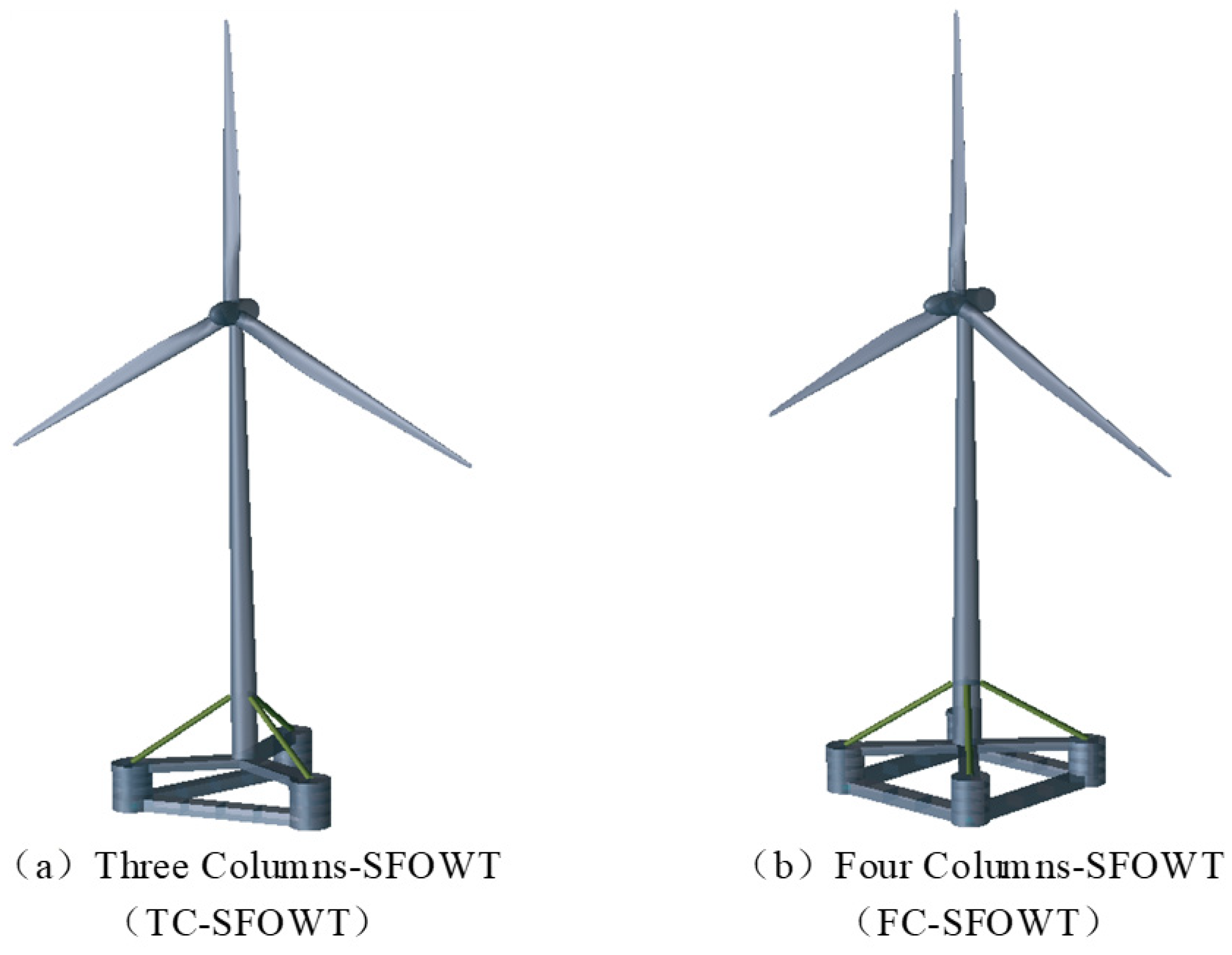
Figure 1.
Overall model of SFOWTs.
Figure 1.
Overall model of SFOWTs.
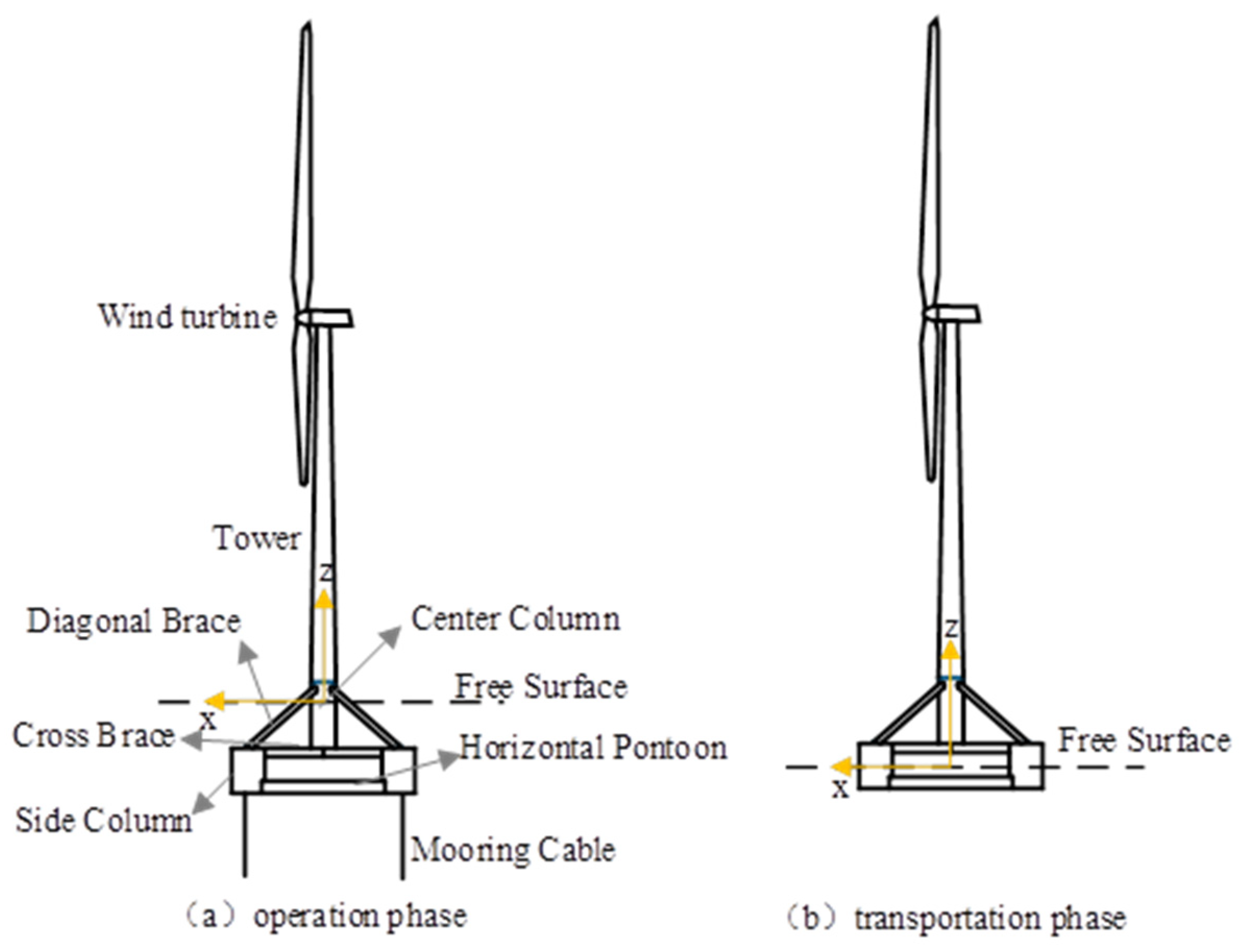
Figure 2.
The structure of the SFOWT.
Figure 2.
The structure of the SFOWT.
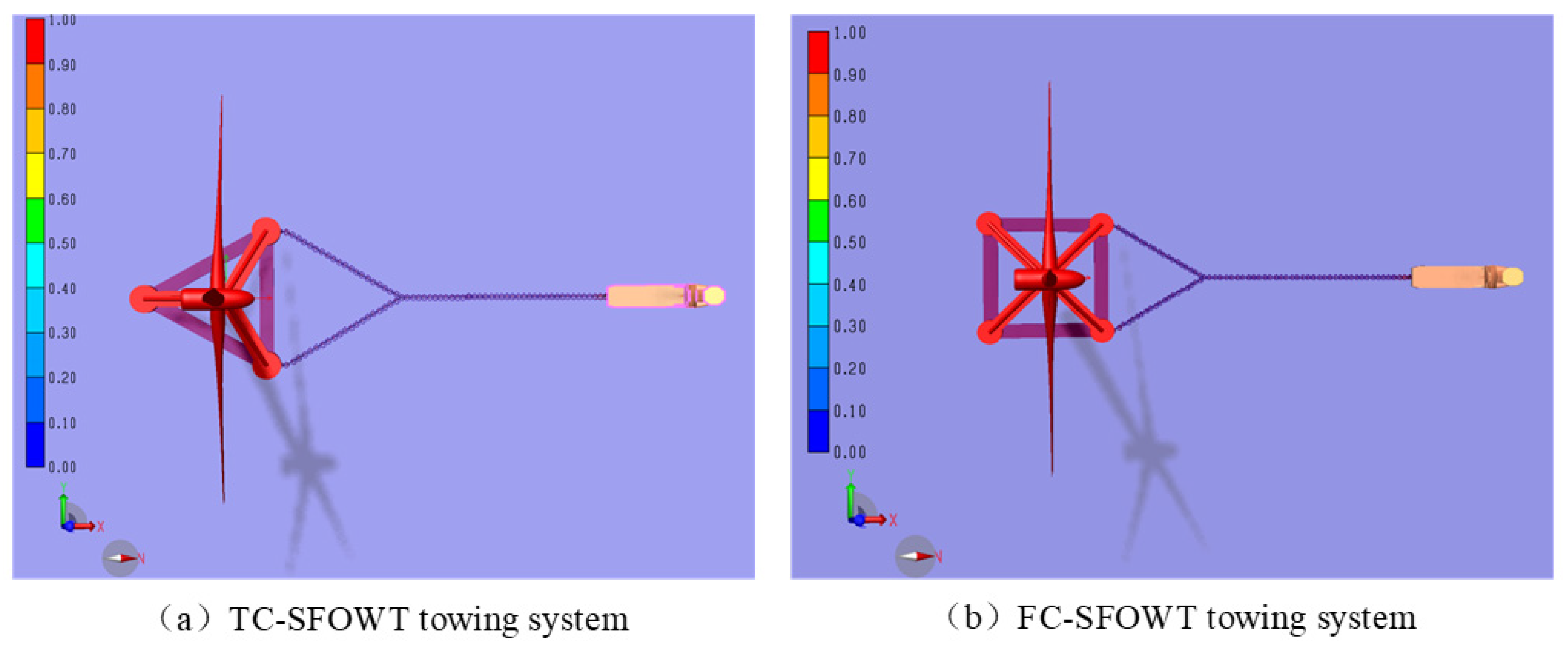
Figure 3.
Bird’s eye view of the TC-SFOWT and FC-SFOWT towing system.
Figure 3.
Bird’s eye view of the TC-SFOWT and FC-SFOWT towing system.
Figure 4.
Definition of wave directions under the towing condition.
Figure 4.
Definition of wave directions under the towing condition.
Figure 5.
Wave directions.
Figure 5.
Wave directions.
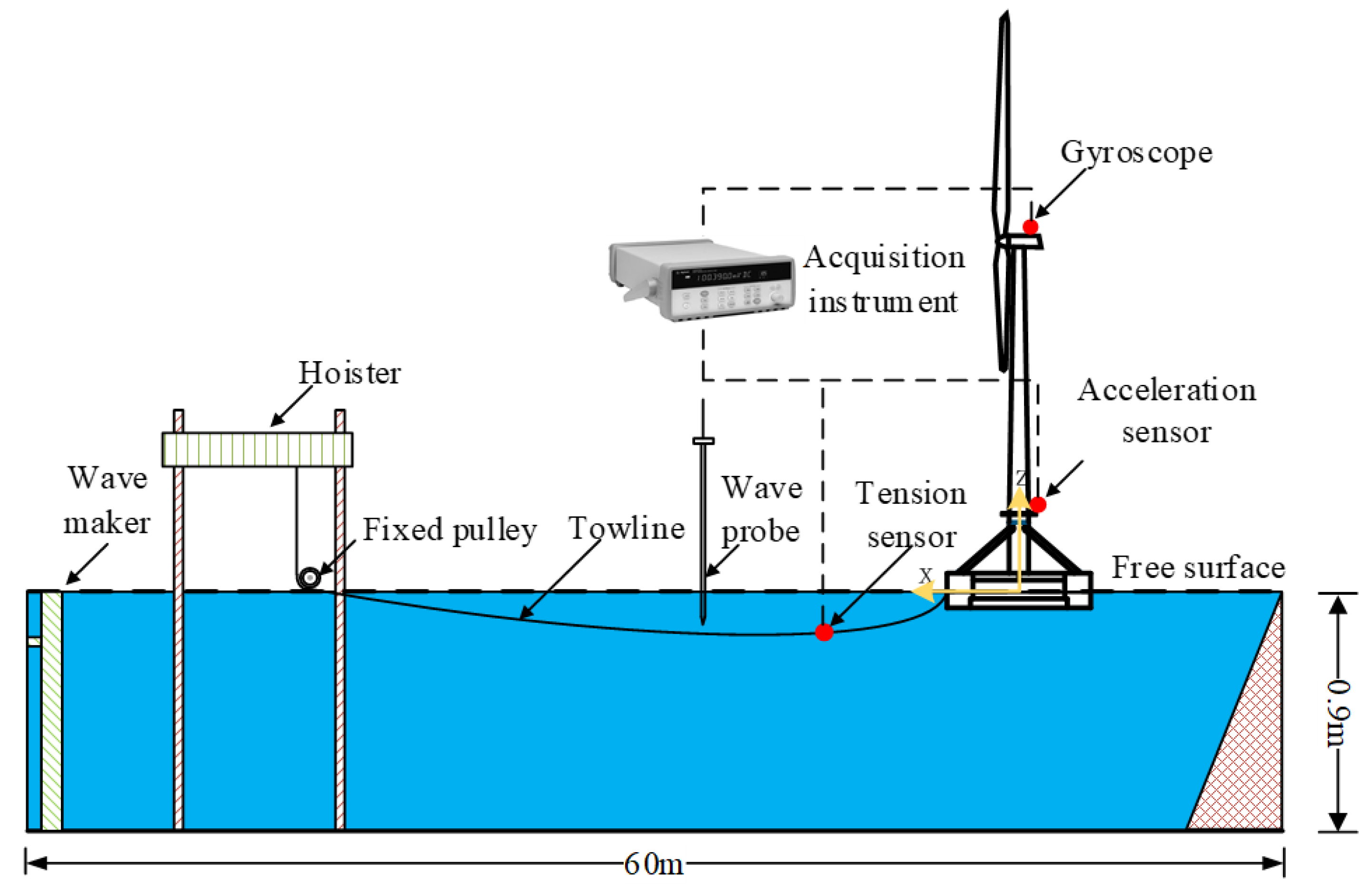
Figure 6.
Schematic diagram of towing experiments.
Figure 6.
Schematic diagram of towing experiments.
Figure 7.
Model-scale of 10MW TC-SFOWT and FC-SFOWT in the wave basin. (a) TC-SFOWT, (b) FC-SFOWFT.
Figure 7.
Model-scale of 10MW TC-SFOWT and FC-SFOWT in the wave basin. (a) TC-SFOWT, (b) FC-SFOWFT.
Figure 8.
Heave motion RAOs of SFOWTs.
Figure 8.
Heave motion RAOs of SFOWTs.
Figure 9.
Roll motion RAOs of SFOWTs.
Figure 9.
Roll motion RAOs of SFOWTs.
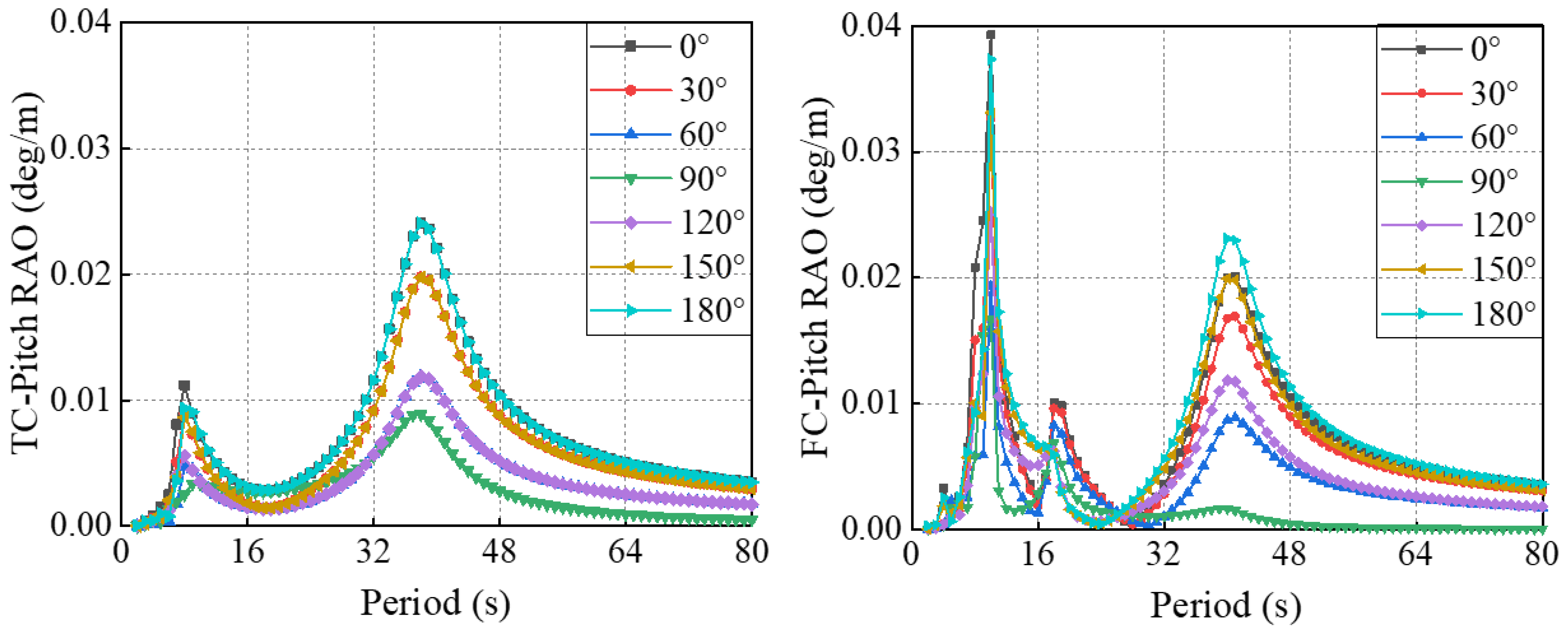
Figure 10.
Pitch RAOs of SFOWTs.
Figure 10.
Pitch RAOs of SFOWTs.
Figure 11.
Free-decay and frequency spectrum. (a) Free-decay in heave motion, (b) free-decay in roll motion, (c) free-decay in pitch motion.
Figure 11.
Free-decay and frequency spectrum. (a) Free-decay in heave motion, (b) free-decay in roll motion, (c) free-decay in pitch motion.
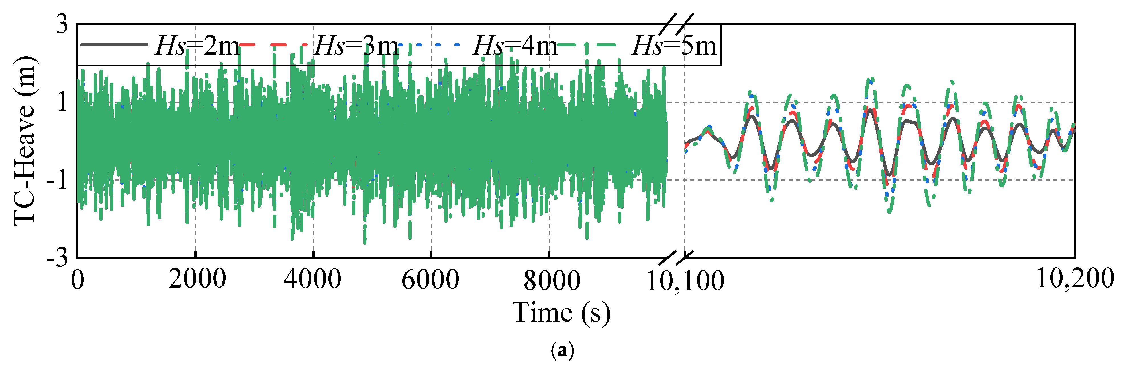
Figure 12.
Time series of the SFOWT under different wave height conditions (Tp = 8.9s). (a) Heave motion of TC-SFOWT, (b) heave motion of FC-SFOWT, (c) pitch motion of TC-SFOWT, (d) pitch motion of FC-SFOWT, (e) roll motion of TC-SFOWT, (f) roll motion of FC-SFOWT, (g) towing force of TC-SFOWT, (h) towing force of FC-SFOWT.
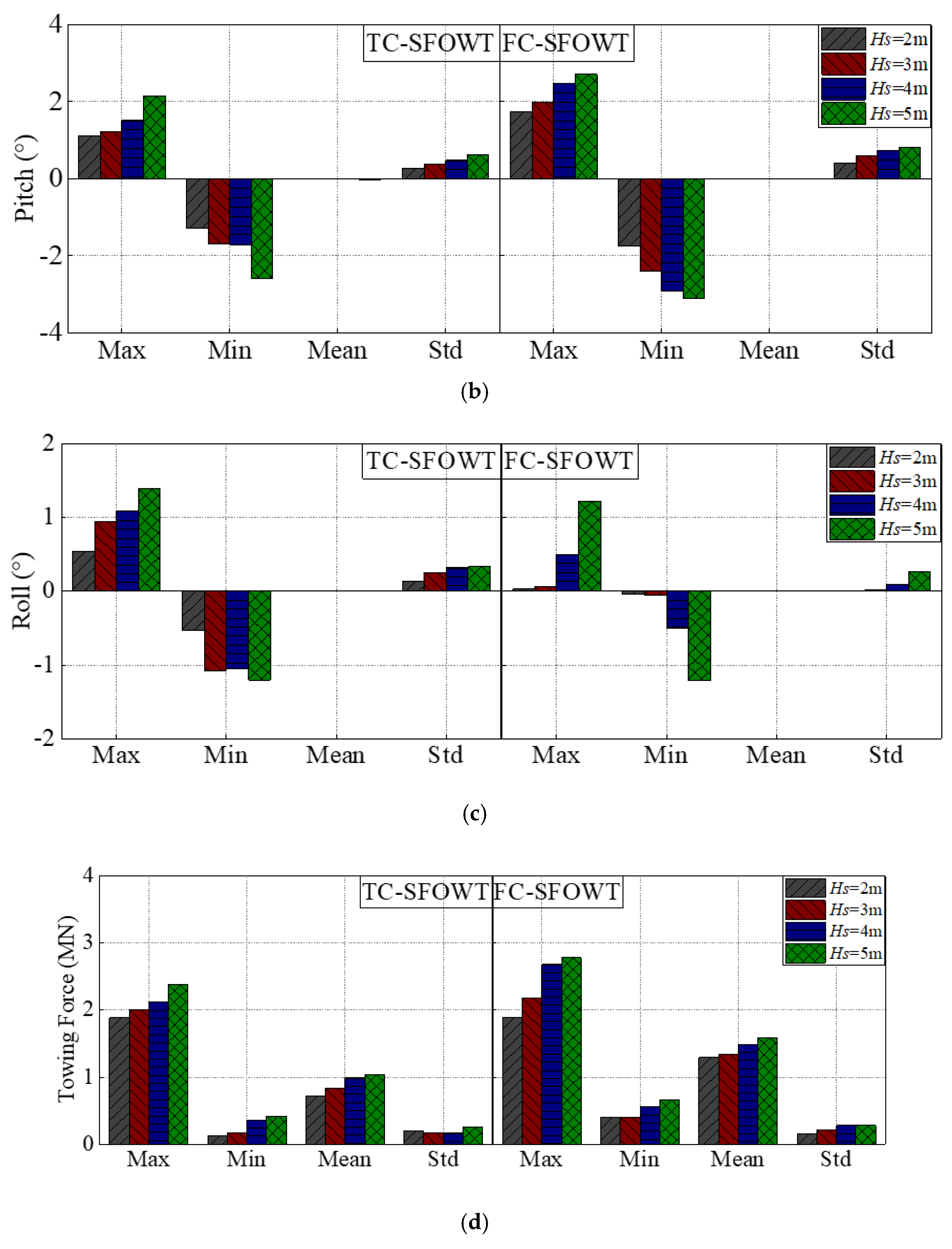
Figure 13.
Statistics of the SFOWTs under different wave height conditions (Tp = 8.9). (a) Heave motion, (b) pitch motion, (c) roll motion, (d) towing force.
Figure 13.
Statistics of the SFOWTs under different wave height conditions (Tp = 8.9). (a) Heave motion, (b) pitch motion, (c) roll motion, (d) towing force.
Figure 14.
Power spectra of the SFOWT motion under different wave height conditions (Tp = 8.9 s). (a) Heave motion, (b) pitch motion, (c) roll motion.
Figure 14.
Power spectra of the SFOWT motion under different wave height conditions (Tp = 8.9 s). (a) Heave motion, (b) pitch motion, (c) roll motion.
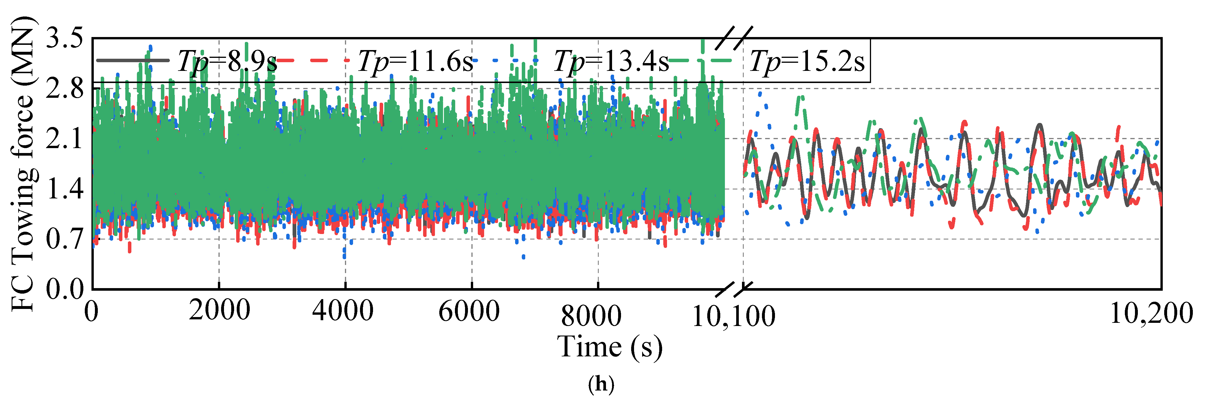
Figure 15.
Time series of the SFOWTs under different wave period conditions (Hs = 5 m). (a) Heave motion of TC-SFOWT, (b) heave motion of FC-SFOWT, (c) pitch motion of TC-SFOWT, (d) pitch motion of FC-SFOWT, (e) roll motion of TC-SFOWT, (f) roll motion of FC-SFOWT, (g) towing force of TC-SFOWT, (h) towing force of FC-SFOWT.
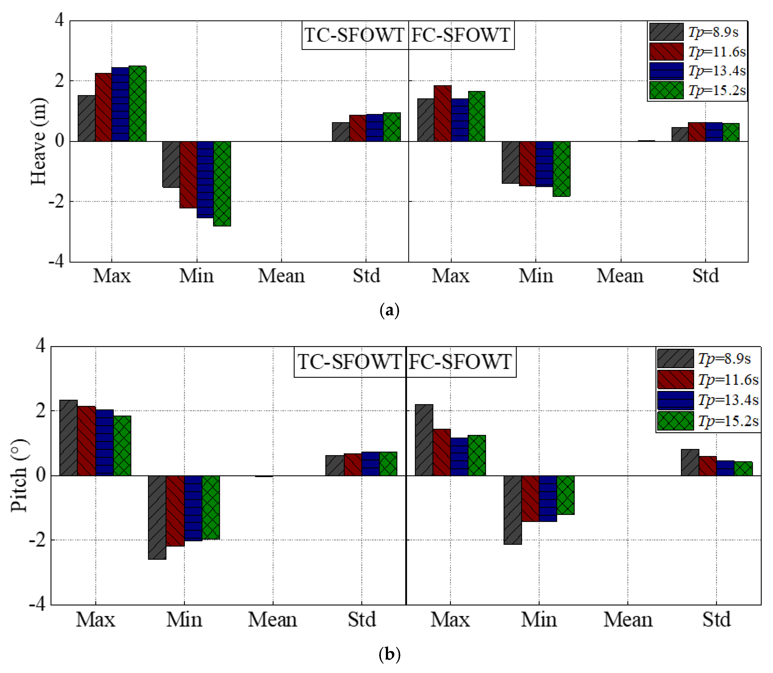
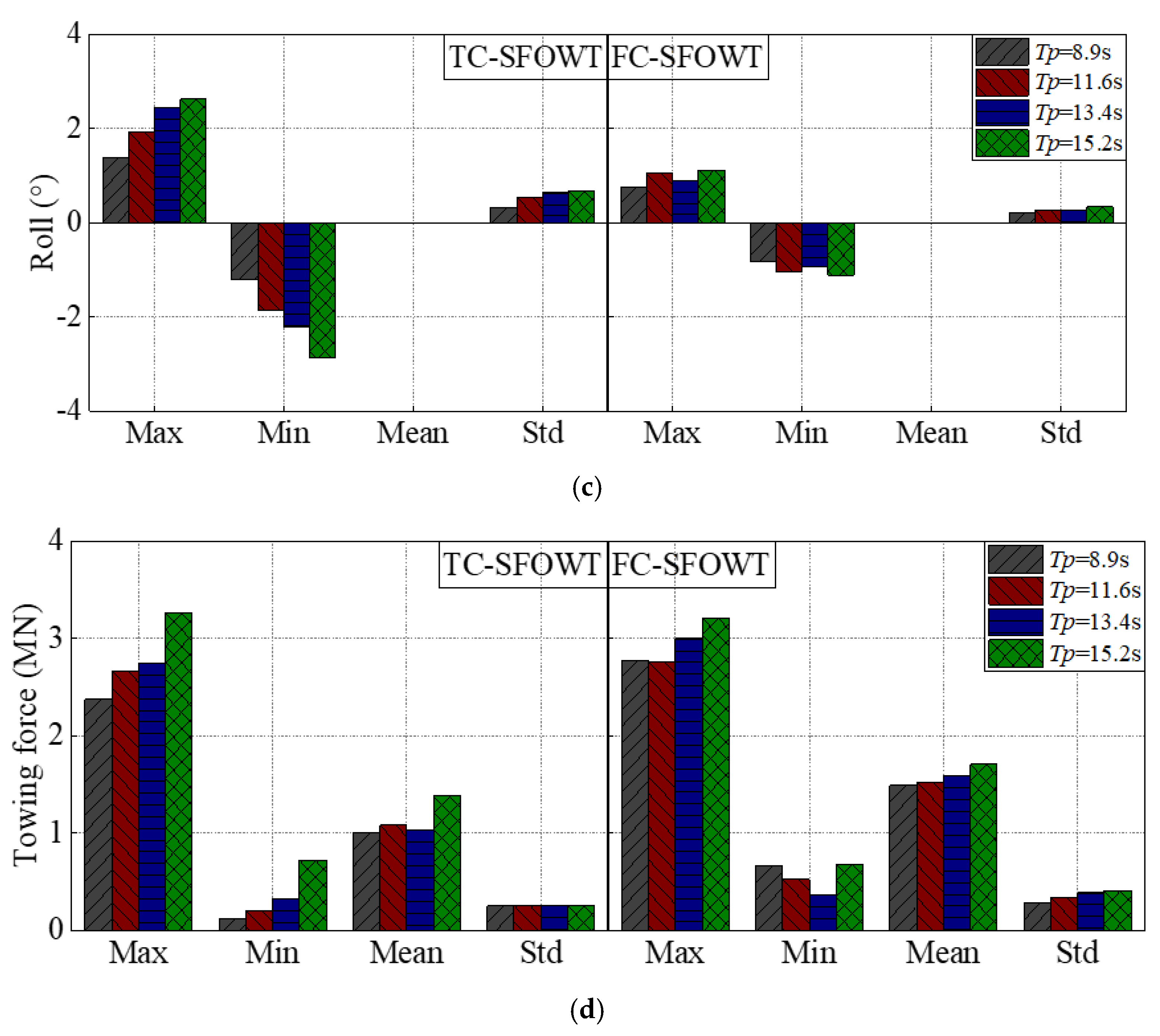
Figure 16.
Statistics of the SFOWTs under different wave period conditions (Hs = 5 m). (a) Heave motion, (b) pitch motion, (c) roll motion, (d) towing force.
Figure 16.
Statistics of the SFOWTs under different wave period conditions (Hs = 5 m). (a) Heave motion, (b) pitch motion, (c) roll motion, (d) towing force.
Figure 17.
Power spectra of the SFOWT motion under different wave period conditions (Hs = 5 m). (a) Heave motion, (b) pitch motion, (c) roll motion.
Figure 17.
Power spectra of the SFOWT motion under different wave period conditions (Hs = 5 m). (a) Heave motion, (b) pitch motion, (c) roll motion.
Table 1.
Main parameters of the DTU 10MW reference wind turbine [
21].
Table 1.
Main parameters of the DTU 10MW reference wind turbine [
21].
| Item | Value |
|---|
| Rated power (MW) | 10 |
| Cut-in, rated, cut-out wind speeds (m/s) | 4, 11.4, 25 |
| Number of blades | 3 |
| Diameter of rotor (m) | 178.3 |
| Blade length (m) | 86.366 |
| Hub height (m) | 119 |
| Mass of impeller, nacelle, tower (kg) | 227,962, 446,036, 628,422 |
| Overall center of gravity (CoG) (m) | (−0.3, 0.0, 85.5) |
Table 2.
Main parameters of the towing system of SFOWTs.
Table 2.
Main parameters of the towing system of SFOWTs.
| Item | TC-SFOWT | FC-SFOWT |
|---|
| Diameter of center column (m) | 8.3 | 8.3 |
| Diameter of vertical pontoon (m) | 12.68 | 11.0 |
| Diameter of side column (m) | 15.0 | 15.0 |
| Distance between side column (m) | 61.24 | 50.0 |
| Width and height of horizontal pontoon (m) | 6.3, 4.4 | 6.6, 4.0 |
| Diameter of diagonal brace (m) | 2.5 | 2.5 |
| Towing speed (knots) | 4 | 4 |
| Draft (m) | 5.2 | 6.0 |
| Angle of towing bridle (°) | 60 | 60 |
| Length of towing line (m) | 100 | 100 |
| Mass of platform (kg) | 4,819,000 | 4,812,000 |
| Mass moment of inertia in roll (kg∙m2) | 1.94 × 10⁹ | 2.31 × 10⁹ |
| Mass moment of inertia in pitch (kg∙m2) | 1.94 × 10⁹ | 2.31 × 10⁹ |
| Mass moment of inertia in yaw (kg∙m2) | 3.41 × 10⁹ | 4.02 × 10⁹ |
Table 3.
Load case for verification of numerical model.
Table 3.
Load case for verification of numerical model.
| Significant Wave Height (m) | Peak Period (s) | Towing Speed (m/s) |
|---|
| Simulation | Experiment | Simulation | Experiment | Simulation | Experiment |
|---|
| 5 | 0.0625 | 8.9 | 1.0 | 2.06 | 0.23 |
Table 4.
Comparison results for model validation in full scale. (Note: Num., Exp., and Max. are the abbreviations for numerical, experimental, and maximum).
Table 4.
Comparison results for model validation in full scale. (Note: Num., Exp., and Max. are the abbreviations for numerical, experimental, and maximum).
| Pitch Motion (°) | Towing Force (N) |
|---|
| TC-SFOWT | FC-SFOWT | TC-SFOWT | FC-SFOWT |
|---|
| Num. Max. | Exp. Max. | Num. Max. | Exp. Max | Num. Mean | Exp. Mean | Num. Mean | Exp. Mean |
|---|
| 2.446 | 2.746 | 2.704 | 2.587 | 1,200,543 | 1,254,400 | 1,771,500 | 1,690,562 |
Table 5.
Viscous damping for SFOWTs.
Table 5.
Viscous damping for SFOWTs.
| DOFs | Inertial Mass (kg) | Added Mass (kg) | Restoring Stiffness (N/m, N/rad) | Viscous Damping
(N/(m/s), N(rad/s)) |
|---|
| Heave | TC-SFOWT | 6.02 × 10⁶ | 6.94 × 10⁶ | 3.78 × 10⁶ | 1.40 × 10⁶ |
| FC-SFOWT | 6.01 × 10⁶ | 1.47 × 10⁷ | 3.78 × 10⁶ | 1.77 × 10⁶ |
| Roll | TC-SFOWT | 2.05 × 10¹⁰ | 2.68 × 10⁹ | 5.78 × 10⁸ | 7.32 × 10⁸ |
| FC-SFOWT | 2.08 × 10¹⁰ | 5.23 × 10⁹ | 6.69 × 10⁸ | 8.34 × 10⁸ |
| Pitch | TC-SFOWT | 2.05 × 10¹⁰ | 2.63 × 10⁹ | 5.78 × 10⁸ | 7.32 × 10⁸ |
| FC-SFOWT | 2.08 × 10¹⁰ | 4.58 × 10⁹ | 6.69 × 10⁸ | 8.25 × 10⁸ |
Table 6.
Natural frequencies in 3 DOFs of the SFOWTs.
Table 6.
Natural frequencies in 3 DOFs of the SFOWTs.
| DOFs | Frequency (Hz) |
|---|
| Heave | TC-SFOWT | 0.070 |
| FC-SFOWT | 0.056 |
| Roll | TC-SFOWT | 0.025 |
| TC-SFOWT | 0.026 |
| Pitch | FC-SFOWT | 0.024 |
| FC-SFOWT | 0.026 |
Table 7.
Typical wave conditions under different wave heights.
Table 7.
Typical wave conditions under different wave heights.
| Wave Conditions | C1 | C2 | C3 | C4 |
|---|
| Significant wave height (Hs) | 2 m | 3 m | 4 m | 5 m |
| Peak period (Tp) | 8.9 s | 8.9 s | 8.9 s | 8.9 s |
Table 8.
Typical wave conditions under different wave periods.
Table 8.
Typical wave conditions under different wave periods.
| Wave Conditions | C5 | C6 | C7 | C8 |
|---|
| Significant wave height (Hs) | 5 m | 5 m | 5 m | 5 m |
| Peak period (Tp) | 8.9 s | 11.6 s | 13.4 s | 15.2 s |


