Article

Multi-Pass Welding Distortion Analysis Using Layered Shell Elements Based on Inherent Strain

1
Department of Naval Architecture and Ocean Engineering, Chonnam National University, Yeosu 59626, Korea
2
Department of Mechanical Engineering, Korea Advanced Institute of Science and Technology, 291 Daehak-ro, Yuseong-gu, Daejeon 34141, Korea
3
Department of Naval Architecture & Ocean Engineering, Chungnam National University, Daejeon 34134, Korea
*
Author to whom correspondence should be addressed.
J. Mar. Sci. Eng. 2021, 9(6), 632; https://doi.org/10.3390/jmse9060632
Submission received: 19 May 2021 / Revised: 30 May 2021 / Accepted: 4 June 2021 / Published: 6 June 2021
(This article belongs to the Special Issue Ship Structures)

Abstract

:
In this article, a layered shell element-based, elastic finite element method for predicting welding distortion in multi-pass welding is developed. The welding distortion generated in each pass can be predicted by employing layer-by-layer equivalent plastic strains as thermal expansion coefficients and using the heat-affected zone (HAZ) width as the mesh size. The final distortion can be expressed as the sum of the distortions for each pass. This study focuses on extraction of the equivalent plastic strain and HAZ width through 3D thermal elastic plastic analysis (TEPA) for each pass. The input variables extracted from each pass can be converted and added to simulate the final distortion of the multi-pass welding. A 10 mm thick, multi-pass butt-welded joint, subjected to three passes, is simulated via the proposed method. The predicted welding distortion is compared with the 3D TEPA results and the measured experimental data. The outcome indicates that good agreement can be obtained.

1. Introduction

Welding distortion inevitably occurs in welded structures. Uneven temperature distribution occurs due to welding, resulting in residual stress and permanent deformation [1,2]. This causes problems such as a decrease in dimensional accuracy and a decrease in productivity. If welding deformation can be predicted through computer simulation, production plans, such as structural changes to reduce welding distortion, can be established [3]. The biggest problem in implementing welding distortion analysis by computer simulation is the fact that welding is a very complex multi-physics phenomenon [4]. Actual welding is a multi-physical phenomenon in which thermal, mechanical, and metallurgical effects occur, and so, the more accurately reflected these are, the longer the calculation time takes exponentially [5,6,7,8,9]. Since the analysis time takes several hours for unit specimens with a welding length of several hundred millimeters, it is practically impossible to apply 3D TEPA to a welded structure with a length of several tens of meters [1].
Therefore, since the 1980s, to overcome this problem of high calculation cost, simplified methods involving reduced computation time, based on inherent strain theory, have been developed [10,11]. Inherent strain refers to the permanent deformation generated in the heat-affected zone (HAZ) [12]. The inherent strain value can be determined by adding the inelastic strain values in the HAZ by using numerical analysis, such as 3D TEPA, and experimental validation [13]. The estimated inherent strain value can be assigned as an elastic load, such as an equivalent nodal load or equivalent thermal strain load to a finite element (FE) model [14]. With regards to the practical application of welding analysis to large welded structures, welding distortion analysis methods based on equivalent thermal strain and shell elements have been proposed [15,16]. In particular, the method developed by Ha [16], which is known as the “strain as direct boundary (SDB) method,” uses the virtual thermal expansion coefficient and virtual temperature distribution in an elastic FEM-based shell model to simulate the plastic deformation that occurs in the HAZ. Unlike conventional shell element-based welding distortion analysis techniques, such as the equivalent load method [17], the SDB method uses scalar input variables for reduced modeling time. Chung et al. [18] also developed a layered shell-based welding distortion analysis method, which can estimate the welding distortion of both the plate and stiffener in fillet welds; this cannot be predicted using the conventional SDB method. Welding distortion analysis methods, based on thermal strain and shell elements, can be effectively used for welding distortion analysis of large welding structures because they use both scalar input variables, to reduce the modeling time, and shell model-based FEM, which can also reduce the computation time effectively. However, most previous research has focused on single-pass welding only. As multi-pass welding is widely used to join thick plates, welding distortion analysis methods based on thermal strain and shell elements should be extended to include multi-pass welding.
In this paper, by exploiting the advantage of the layered shell element-based method, which can provide different thermal strain values per layer, we propose a layered shell element-based elastic FEM for predicting welding distortion in multi-pass welding. We focus on extracting the equivalent strain and HAZ width through 3D TEPA, along with its application to layered, shell element-based elastic FEM. A 10 mm thick, multi-pass butt-welded joint, subjected to three passes, is simulated using the proposed method and the predicted welding distortion is then compared with that obtained from a conventional method and experimentally measured data.

2. SDB Method

The core principle of the SDB method is that the inherent strain can be used as the equivalent thermal strain. In commercial FEM codes, the thermal expansion coefficient can be used as a tool to simulate thermal strain when the temperature variances at specific nodes are given. In the welding distortion analysis method developed by Ha [16], artificial top and bottom temperatures at the nodes, the mesh size at the welding region, and the thermal expansion coefficient are taken as input parameters. The shrinkage can be estimated from the average value obtained from the artificial top and bottom temperatures, whereas the angular deformation can be estimated from the mean difference between the artificial top and bottom temperatures. The model mesh size is equivalent to the maximum width of the inherent strain region [18]. This methodology is based on an experimental case study in which the inherent strain, which was used as the thermal coefficient value, was measured. The artificial temperature values were estimated by analyzing the HAZ shape by conducting 3D TEPA and experimental validation. For more detailed explanations, please refer to Ha [16] and Chung et al. [18].
For multi-pass welding analysis, Ha and Yang [19] extended the conventional SDB method. In the case of multi-pass welding, when the welding of a specific pass is performed, the welding deformation is determined by the thickness up to the stage accumulated in the weld. However, in shell element-based FEM, the bending stiffness (which affects the degree of deformation) is determined by the thickness of the adjacent plate, which is similar to the final thickness following welding completion. Thus, shell element-based welding distortion analysis is performed for a state with considerably higher stiffness than the actual condition encountered in multi-pass welding. Considering these issues, Ha and Yang [19] idealized the problem by employing the following major assumptions:
A.
Each pass has the same cross-sectional area;
B.
All passes are stacked in the layer direction;
C.
The area of the HAZ generated by each pass is ignored, but the bead reinforcement is considered;
D.
The deformation due to the internal residual stress caused by the temperature differences between passes is neglected.
By applying this method, it is possible to implement shell element-based welding distortion analysis in the case of multi-pass welds of the same joint shape, in which the deformation increases with the number of passes. According to a case study by Ha and Yang [19], the proposed method can qualitatively predict that the total amount of angular distortion increases as the number of passes increases, but actual experimental values show an error of 40–50%. This suggests that a limit exists when the idealized assumptions are actually applied, with the main problem being the difficulty in specifying the inherent strain value, which is equal to the thermal expansion coefficient in the SDB method. As the welding passes accumulate, the residual stress and inherent strain values are also influenced by each pass. Ultimately, the inherent strain value generated in each pass is different. Furthermore, it cannot be confidently assumed that the obtained value represents the entire inherent strain region. For a more detailed explanation of this problem, please refer to Ha and Yang [19].

3. Proposed Method

3.1. Layered Shell Element-Based Welding Distortion Analysis Method

Chung et al. [18] introduced a novel approach using layered shell element-based FEM. The main contribution of this method is that composite shell elements can be used for the different thermal expansion coefficients along the joint thickness in fillet welding; hence, it is possible to represent the deformations of both members simultaneously, which cannot be achieved using the conventional SDB method. In the shell element model, the intersecting region at which the base plate and fillet member are attached share the same node; thus, the temperature degree of freedom is shared at the intersection nodes. However, in the composite shell element-based method, different thermal coefficients are employed for each layer representing the inherent region; thus, the HAZ area can be separately modeled for both members, and it is possible to represent the distortions of both members simultaneously.
Reviewing Section 2, it is apparent that the conventional SDB method for multi-pass welding involves major assumptions that may not apply to actual welding conditions, possibly generating prediction errors. Note that assumptions (C) and (D) are critical and may decrease prediction accuracy. First, in the case of V-groove multi-pass butt welding, for which the number of passes is relatively small, it is common to fill in the lateral, rather than layer, direction. This corresponds to adherence to the conventional third assumption, which generates greater angular distortion than the actual state. Second, based on a literature survey [20,21], the temperature difference between passes has a significant effect on the final weld deformation. Thus, following the conventional multi-pass SDB method, it is possible to predict the qualitative results regarding the increase in deformation with an increased number of passes; however, it is difficult to accurately predict the angular distortion. Moreover, in the case of multi-pass welding, it is difficult to specify the inherent strain value (representing the final deformation) based on an experiment. As a substitute method, multi-pass welding analysis can be performed through numerical analysis. Then, the inherent strain value for each layer can be calculated in each pass and directly applied to layered shell element-based welding distortion analysis. As noted above, a previous study on fillet welding [18] focused on modeling the HAZ shapes of both members to simulate their distortions simultaneously. However, in this study, we focus on extraction of the layer-by-layer inherent strain values according to the 3D TEPA results for each pass of the multi-pass welding simulations, followed by accumulation of these distortions to predict the final distortion.

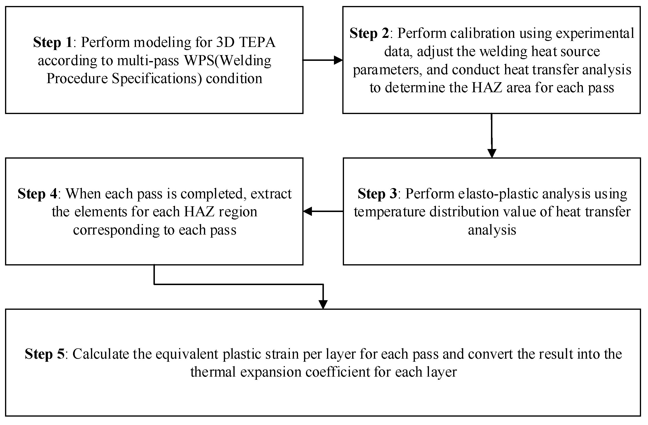
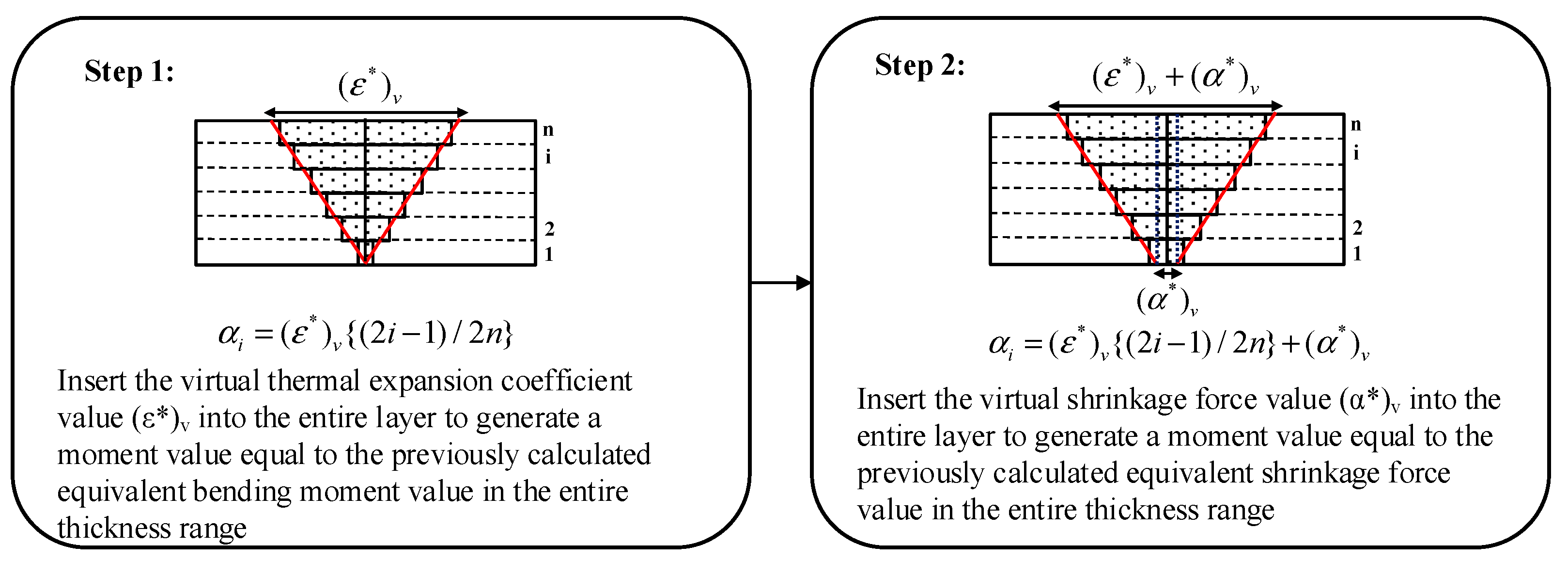
3.2. Proposed Analysis Procedure Based on 3D TEPA Results

As discussed in the previous sections, in order to perform the layered shell element-based welding distortion analysis, definition of the input variables, i.e., the thermal coefficients and mesh size, is required. The thermal coefficients for each layer correspond to the equivalent plastic strain, and the mesh size in the welding region is identical to the equivalent HAZ width. The welding deformation is determined by the thickness up to the stage accumulated in the weld; thus, the element birth and death technique [22] is used for both heat transfer analysis and elasto-plastic mechanical analysis. In the pre-processing stage for the 3D TEPA, the weldment for each pass is modeled following the bead shape and excluding the reinforcement. For the heat transfer analysis, a double ellipsoidal heat source model [23] is used and the heat source parameters are calibrated through comparison with the experimentally measured temperatures. The elasto-plastic analysis is performed next. The heat transfer analysis results, i.e., the time-temperature distribution data, are used for the elasto-plastic analysis. Following each welding pass, the equivalent plastic strains at the HAZ area are extracted. In conventional composite shell element-based welding analysis, the HAZ shape is depicted in order to extract the inherent strain value. In this study, however, we use the element plastic strain value obtained from the elasto-plastic analysis directly when obtaining the equivalent strain value in the HAZ area.
The assumptions employed in the proposed method are as follows:
A.
The deformation occurring in each pass is caused by the inherent strain region occurring below the minimum equivalent thickness accumulated in each pass;
B.
Only the plastic strain in the inherent strain region in the transverse direction is considered;
C.
Reinforcement is neglected;
D.
In the 3D TEPA analysis, the strain of each pass is calculated after cooling for each pass is complete.
The shrinkage generated by the inherent strain distributed in the elements can be replaced by the inherent deformation introduced as the discontinuity of the nodal displacements [24]. As the angular distortion is generated by the transverse shrinkage difference in the thickness direction, we consider an inherent strain region containing nine elements with three layers (Figure 1). Furthermore, we assume that each element has a unique transverse-direction plastic strain following the 3D TEPA. The final deformation of each layer in the inherent strain zone can be presented as the sum of the product of the element size (transverse direction) and the plastic strain, such that:
δ x 1 = a 1 ε x 1 , 1 + a 2 ε x 2 , 1 + a 3 ε x 3 , 1 , δ x 2 = a 1 ε x 1 , 2 + a 2 ε x 2 , 2 + a 3 ε x 3 , 2 , δ x 3 = a 1 ε x 1 , 3 + a 2 ε x 2 , 3 + a 3 ε x 3 , 3 ,
where
δ x i = d i s p l a c e m e n t o f i t h l a y e r i n i n h e r e n t s t r a i n r e g i o n , ε x i , j = p l a s t i c s t r a i n ( x d i r e c t i o n ) o f i t h e l e m e n t o f j t h l a y e r i n i n h e r e n t s t r a i n r e g i o n , a i = e q u i v a l e n t s i z e ( t r a n s v e r s e d i r e c t i o n ) o f i t h e l e m e n t i n e a c h l a y e r .
The 3D elasto-plastic result can be used to determine the transverse-direction displacement according to the thickness in the inherent strain region. It is possible to use this result directly in the composite shell analysis. The thermal coefficients for each layer, which are used as input variables in the composite shell method, are obtained as follows [18]:
α i , 1 = k = 1 n ε k , i , 1 , 1 b k , i , 1 B 1 , α i , j ( j 2 ) = k = 1 n ( ε k , i , j , j ε k , i , j , j 1 ) b k , i , 1 B j ,
where
α i , j = t h e r m a l e x p a n s i o n o f i t h l a y e r o f j t h p a s s , ε k , i , j , l = p l a t i c s t r a i n ( t r a n s v e r s e d i r e c t i o n ) o f k t h e l e m e n t o f i t h l a y e r w i t h i n j t h p a s s s H A Z w i d t h a f t e r l t h p a s s w e l d i n g , b k , i , j = e q u i v a l e n t l e n g t h ( t r a n s v e r s e d i r e c t i o n ) o f k t h e l e m e n t o f i t h l a y e r w i t h i n j t h p a s s s H A Z w i d t h , B j = e q u i v a l e n t H A Z w i d t h o f j t h p a s s .
One additional step added in the approach proposed in this paper is the subtraction of the amount of plastic strain generated in the previous pass for the elements of the overlapping inherent strain region; this additional step is performed for each pass. In this manner, the input variables for the welding deformation induced in each pass can be obtained separately, and the effect of the residual stress generated in each pass can be reflected. The overall procedure for extracting the equivalent plastic strain and equivalent HAZ width for each pass is summarized in Figure 2.
The next step is converting input variables generated by each pass. The process for obtaining the required thermal expansion coefficient values and the HAZ widths through 3D TEPA is described above. These values are used as factors of the equivalent load to simulate the welding deformation. The final deformation is determined from the sum of the equivalent loads, which cause deformation in each pass. According to the FEM theory for layered shell elements, the stress resultants can be obtained by integrating the stress components per layer in the thickness direction, such that:
N x = t / 2 t / 2 σ x d z = t 2 i = 1 n σ x i Δ ζ i , M x = t / 2 t / 2 σ x z d z = t 2 4 i = 1 n σ x i ζ i Δ ζ i ,
where
N x = n o r m a l f o r c e ( x d i r e c t i o n ) r e s u l t a n t s , z = c o o r d i n a t e s i n t h e t h i c k n e s s d i r e c t i o n f r o m t h e n e u t r a l a x i s , σ x = n o r m a l s t r e s s ( x d i r e c t i o n ) r e s u l t a n t s , ζ i = l o c a t i o n o f t h e i t h l a y e r i n t h e n a t u r a l c o o r d i n a t e s y s t e m , Δ ζ i = i n c r e m e n t o f t h e i t h l a y e r i n t h e n a t u r a l c o o r d i n a t e s y s t e m .
Figure 3 shows the layered shell model and stress distribution diagram conforming to Equation (3). Temperature 1 is assigned to the node corresponding to the weld zone and the stress resultant is obtained using the different thermal expansion coefficient of each layer. The equivalent load, which is calculated from the HAZ size obtained from each pass and the thermal expansion coefficient of each layer, can be calculated from:
N x , j = B j E t j 2 i = 1 n α i Δ ζ i , M x , j = B j E t j 2 4 i = 1 n α i ζ i Δ ζ i ,
where
N x , j = n o r m a l f o r c e ( x d i r e c t i o n ) r e s u l t a n t s o f j t h p a s s , M x , j = b e n d i n g m o m e n t ( x d i r e c t i o n ) r e s u l t a n t s o f j t h p a s s , α i = t h e r m a l e x p a n s i o n c o e f f i c i e n t i n t h e i t h l a y e r , B j = e q u i v a l e n t H A Z w i d t h o f j t h p a s s , t j = e q u i v a l e n t t h i c k n e s s o f j t h p a s s .
The final deformation is obtained from the sum of the equivalent loads of each pass. To simulate the final deformation using composite shell-based welding analysis, it must be possible to simulate the sum of these equivalent loads by adjusting the thermal expansion coefficients of each layer. This can be achieved by introducing a virtual thermal expansion coefficient value and a virtual shrinkage force. The first step is to convert the equivalent load calculated, based on the equivalent thickness of each pass, to the final thickness standard. As the bending stiffness of a plate is proportional to the third power of the thickness, the calculated equivalent bending moment should be proportional to the third power of the value obtained by dividing the final thickness by the equivalent thickness of each pass. Further, the shrinkage force should be proportional to the value obtained by dividing the final thickness by the equivalent thickness of each pass. The final equivalent load can be expressed as:
M x , f i n a l = j = 1 n ( t t j ) 3 M x , j , N x , f i n a l = j = 1 n ( t t j ) N x , j ,
where
N x , f i n a l = f i n a l n o r m a l f o r c e ( x d i r e c t i o n ) r e s u l t a n t s , M x , f i n a l = f i n a l b e n d i n g m o m e n t ( x d i r e c t i o n ) r e s u l t a n t s , t = f i n a l t h i c k n e s s .
The next step is to adjust the thermal expansion coefficient to produce the equivalent bending moment and equivalent shrinkage force. The entire process is outlined in Figure 4.
First, the equivalent bending moment value is adjusted by calibrating the virtual thermal expansion coefficient value ((ε*)v). Next, by adding the same virtual shrinkage force value ((α*)v) to the entire layer, it is possible to adjust the equivalent shrinkage force. The equivalent bending moment value is first adjusted, considering the fact that adding the same coefficient of thermal expansion to the entire layer does not affect the calculation of the previously calculated moment value. Using the input variables, composite shell element-based welding distortion analysis can be performed.

4. Verification Using Experimental Models

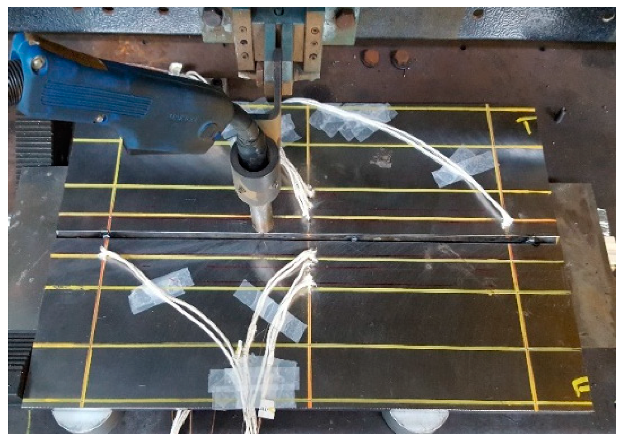
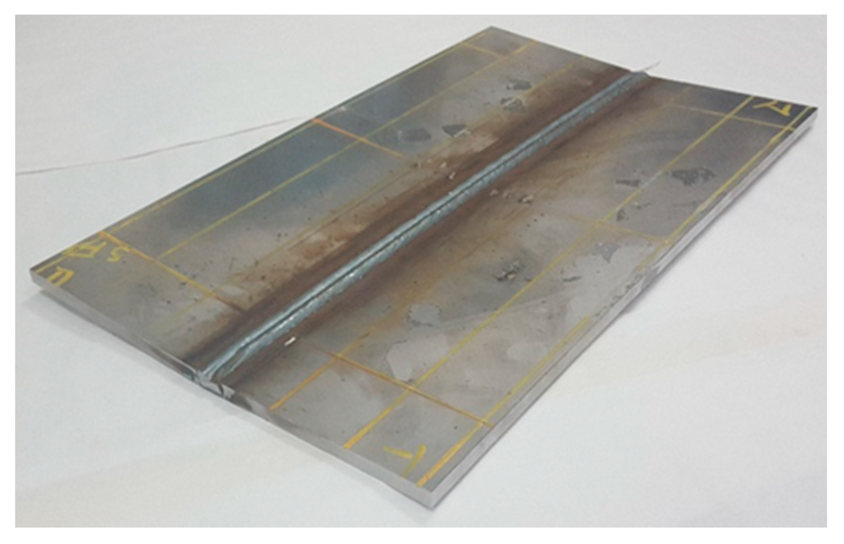
4.1. Experimental Procedure

For validation purposes, multi-pass welding of a butt-joint was conducted. The objective of this experiment was to measure the distortion of the welding specimen and compare the results with the predictions given by the proposed method. For the detailed experiment methods please refer to Perrera [25]. A plate comprised of structural steel SS400 10 mm thick was used for the experiment. The width and length of the plate were 300 and 500 mm, respectively. Figure 5 shows the plate dimensions for the butt-joint.
Three passes were performed. The welding sequence and bead dimensions for the butt-joint are shown in Figure 6. The welding was performed with a programmable machine and at a constant welding speed.
Table 1 lists the welding conditions. A pulsed-gas metal arc welding (P-GMAW) machine was used for welding. A DW-300 OTC Daihan digital inverter (OTC Daihen Inc., Tipp City, OH, USA) [26] was used as the power source. Filler wire was 1.2 mm diameter ER70S-6 mild steel and the wire feeding speed was 6 mm/min. The torch was held perpendicular to the workpiece and the distance from the contact tip to the workpiece was kept at 25 mm with an average extension of 18 mm. The gas flow rate was set to 20 L/min using a composition of Ar and 20% CO2. Figure 7 shows the specimen and equipment for the butt-joint welding.

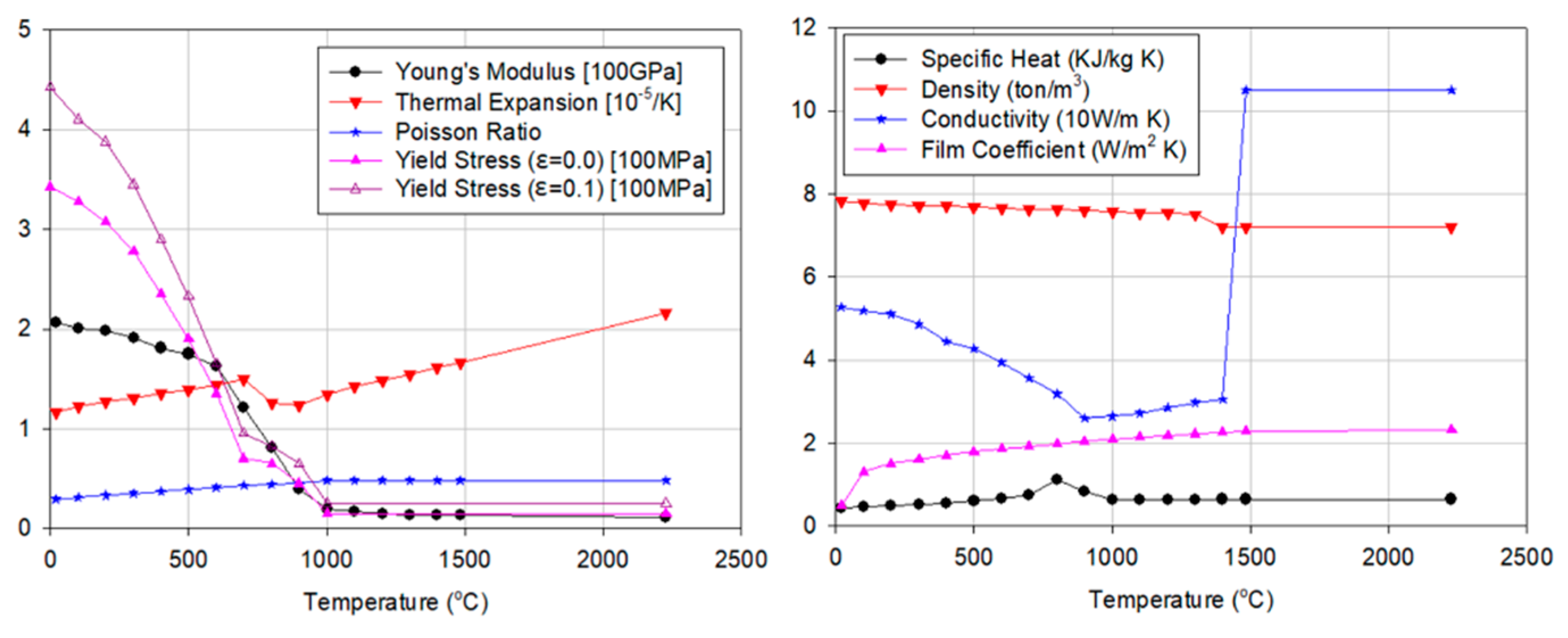
4.2. Numerical Analysis: 3D TEPA

Sequentially coupled 3D TEPA was implemented using Abaqus 6.12 in order to analyze the thermal history of the specimen as well as its welding distortion. The element birth and death technique [19] was used for both heat transfer analysis and elasto-plastic mechanical analysis. First, heat transfer analysis was implemented to obtain the temperature history using a 3D eight-node solid element (DC3D8). The welding heat source was modeled as a double ellipsoidal heat source [20].
The heat intensity distribution of the front and rear half ellipsoids can be expressed as:
q 1 ( x , y , z ) = 6 3 ( f 1 Q ) a b c 1 π π exp ( 3 x 2 a 2 3 y 2 b 2 3 z 2 c 1 2 ) [ W / m 3 ] , q 2 ( x , y , z ) = 6 3 ( f 2 Q ) a b c 2 π π exp ( 3 x 2 a 2 3 y 2 b 2 3 z 2 c 2 2 ) [ W / m 3 ] ,
where a, b, c1, and c2 are the heat flow distribution parameters, f1 and f2 represent the heat input fractions for the front and rear ellipsoids, respectively, and Q is the effective heat input. Here, Q = ηVI, where η, V, and I represent the efficiency, voltage, and current, respectively. Note that η is usually determined empirically. In this study, the heat source parameters were calibrated using experimental results (Table 2). Considering the characteristics of the multi-pass welding procedure, the center of the moving heat source was modified for each pass (Figure 8). The mechanical analysis was performed by importing the transient temperature as a thermal load, with the C3D8R element being applied. The solid mesh system and boundary conditions for the butt-joint are presented in Figure 9.
The arc efficiency was assumed to be 0.85. The heat losses due to radiation and convection were considered together using the constant film coefficient. The latent heat was assumed to be 273,790 W, with the solidus and liquidus temperatures being taken as 1427 °C and 1482 °C, respectively. The emissivity coefficient was taken to be 0.32. The other thermal and mechanical properties [18] used in this analysis are presented in Figure 10.

5. Results and Discussion

5.1. Heat Transfer Analysis Results

The thermal analysis was validated by comparing the simulated cross-sectional profile of each weld pass with the experimental results. In addition, the numerically predicted HAZ was compared with the experimental data. The HAZ is an area of the base metal that has not been melted by the high-temperature heating, but for which the chemical properties are altered. The high temperature from the welding process and the subsequent re-cooling causes these changes from the weld interface to the end of the sensitizing temperature in the metal. To evaluate the width of the HAZ, the phase transformation temperature Ac1 of SS400 was considered as the reference temperature. The isothermal contour of Ac1 temperature is 725 °C [12,15]. It was found that the simulated macro-section HAZ for each weld pass agrees reasonably well with the experimentally obtained HAZ. Further, the modeled sectional profile of the bead is in good agreement with the experimental profile. Figure 11 shows a comparison between the simulated and experimental macro-sections for butt-joint welding. These results establish confidence in the obtained thermal solution, which is used as an input for the mechanical analysis.

5.2. 3D Elasto-Plastic Analysis and Thermal Expansion Values Extraction

By performing elasto-plastic analysis using the temperature distribution of the heat transfer analysis, it is possible to extract the thermal expansion coefficient value for each pass according to the layer in the HAZ region (Figure 12). Through application of Equation (3), the extracted layer-by-layer thermal expansion coefficients are listed in Table 3. Through application of Equation (4), the equivalent loads generated by the inherent strain in each pass are listed in Table 4. Through application of Equation (5), the target moment and target force that generate the final distortion are obtained, as listed in Table 5. The minus direction of the target shrinkage forces means the direction in which the butt-joint shrinks is in the in-plane direction. The minus direction of the target moments means the direction in which the angular distortion occurs is in the upward direction. Next, by introducing (ε*)v and (α*)v, by following the procedure described in the Figure 4, it is possible to extract the input variables that are used for the final distortion prediction (Table 6).

5.3. Comparison of Various Methods

Here, the results from the various numerical and experimental analyses are presented and compared. Figure 13 shows the deformation results from the experiment.
Figure 14 shows the deformation results from the proposed method. For comparison, we also present the results of the multi-pass SDB method (Figure 15). Artificial temperature values were calculated following the procedure of Ha and Yang [16]. The inherent strain value used here was calculated from the equivalent plastic strain values of the elements in the final HAZ region of the 3D TEPA result (Table 7).
Finally, Figure 16 presents a comparison between the existing and proposed methods. It is apparent that the proposed method for the modeling of butt-joint welding can describe the angular deformation precisely. The proposed method is more effective than the existing methods, as the result is closest to the experimental data.

5.4. Discussion

For the existing multi-pass SDB method, although the inherent strain value was extracted from the same 3D TEPA and applied to the shell element-based method, the multi-pass SDB method showed a relatively high difference when compared with the experimental result. It is thought that the accuracy of the result could be improved by supplementing the assumptions of the multi-pass SDB method (i.e., neglect of the effect of the residual stress due to the interpass temperature difference and neglect of the HAZ area for each pass). Nevertheless, the proposed method yielded a difference of approximately 10% from the experiment result. However, this is a limitation of the simplified method. The experiment result showed the difference in each deformation degree depending on the longitudinal bending at each position. However, in the simplified method proposed herein, constant angular distortion could be simulated because of the employed assumptions. At present, only the plastic strain in the transverse direction was considered; thus, the proposed method can be improved by considering a more accurate inherent strain extraction method.

6. Conclusions

In this paper, a layered shell element-based elastic FEM for predicting welding distortions in multi-pass welding was developed. The existing layered shell element-based method depicts the HAZ region and extracts the layer-by-layer thermal strain values. However, in the method proposed in this study, we extracted the layer-by-layer thermal strain values using the element plastic strain values in the HAZ region. Through application of this method, it was possible to consider the influence of the overlapping inherent strain region between each pass. In addition, the influence of the bead shape could also be considered sufficiently. For validation, a 10 mm thick, multi-pass butt-welded joint, subjected to three passes, was simulated using the proposed method; the resultant welding distortion predictions were compared with those given by 3D TEPA and the measured experimental data. The results showed that good agreement can be achieved. Further, compared with the existing method, considerable improvement in accuracy was noted.

Author Contributions

Conceptualization, J.L. and H.C.; methodology, J.L; investigation, D.P.; resources, H.C.; data curation, J.L.; writing—original draft preparation, J.L.; writing—review and editing, J.L. and H.C.; visualization, J.L.; supervision, H.C. All authors have read and agreed to the published version of the manuscript.

Funding

This research was financially supported by the research fund of Chungnam National University.

Institutional Review Board Statement

Not applicable.

Informed Consent Statement

Not applicable.

Data Availability Statement

Not applicable.

Acknowledgments

This article is an addition based on part of J.L.’s doctoral dissertation.

Conflicts of Interest

The authors declare no conflict of interest.

References

  1. Lee, J.M.; Seo, H.D.; Chung, H. Efficient welding distortion analysis method for large welded structures. J. Mater. Process. Technol. 2018, 256, 36–50. [Google Scholar] [CrossRef]
  2. Xin, H.; Correia, J.A.F.O.; Veljkovic, M.; Berto, F.; Manuel, L. Residual stress effects on fatigue life prediction using hardness measurements for butt-welded joints made of high strength steels. Int. J. Fatigue 2021, 147, 106175. [Google Scholar] [CrossRef]
  3. Lee, J.; Chung, H. Modified Equivalent Load Method for Welding Distortion Analysis. J. Mar. Sci. Eng. 2020, 8, 794. [Google Scholar] [CrossRef]
  4. Lindgren, L.E. Numerical modelling of welding. Comput. Methods Appl. Mech. Eng. 2006, 195, 6710–6736. [Google Scholar] [CrossRef]
  5. Lee, J. Development of Efficient Welding Distortion Analysis Method for Large Welded Structure. Ph.D. Dissertation, Korea Advanced Institute of Science and Technology, Daejeon, Korea, 2019. [Google Scholar]
  6. Ding, J. Thermo-Mechanical Analysis of Wire and Arc Additive Manufacturing Process. Ph.D. Dissertation, Cranfield University, Cranfield, UK, 2012. [Google Scholar]
  7. Chen, B.-Q.; Guedes Soares, C. Experimental and numerical investigation on welding simulation of long stiffened steel plate specimen. Mar. Struct. 2021, 75, 102824. [Google Scholar] [CrossRef]
  8. Hammad, A.; Churiaque, C.; Sánchez-Amaya, J.M.; Abdel-Nasser, Y. Experimental and numerical investigation of hybrid laser arc welding process and the influence of welding sequence on the manufacture of stiffened flat panels. J. Manuf. Process. 2021, 61, 527–538. [Google Scholar] [CrossRef]
  9. Perić, M.; Garašić, I.; Nižetić, S.; Dedić-Jandrek, H. Numerical Analysis of Longitudinal Residual Stresses and Deflections in a T-joint Welded Structure Using a Local Preheating Technique. Energies 2018, 11, 3487. [Google Scholar] [CrossRef] [Green Version]
  10. Ueda, Y.; Kim, Y.C.; Yuan, M.G. A predicting method of residual stress using source of residual stress (report I): Characteristics of inherent strain (source of residual stress). Trans. Jpn. Weld. Res. Inst. 1989, 18, 135–141. [Google Scholar]
  11. Ueda, Y.; Yuan, M.G. A predicting method of welding residual stress using source of residual stress (Report II): Determination of standard inherent strain. Trans. Jpn. Weld. Res. Inst. 1989, 18, 143–150. [Google Scholar]
  12. Ueda, Y.; Yuan, M.G. A predicting method of welding residual stress using source of residual stress (Report III): Prediction of residual stresses in T- and I-joints using inherent strains. Trans. Jpn. Weld. Res. Inst. 1993, 22, 157–168. [Google Scholar]
  13. Deng, D.; Murakawa, H.; Ma, N. Predicting welding deformation in thin plate panel structure by means of inherent strain and interface element. Sci. Technol. Weld. Join. 2012, 17, 13–21. [Google Scholar] [CrossRef]
  14. Park, J.; An, G. Prediction of the welding distortion of large steel structure with mechanical restraint using equivalent load methods. Int. J. Naval Archit. Ocean Eng. 2017, 9, 315–325. [Google Scholar] [CrossRef]
  15. Jung, H.; Tsai, C.L. Plasticity-based distortion analysis for fillet welded thin-plate T-joints. Weld. J. 2004, 83, 177–187. [Google Scholar]
  16. Ha, Y.S. Development of thermal distortion analysis method on large shell structure using inherent strain as boundary condition. J. Soc. Nav. Archit. Korea 2008, 45, 93–100. [Google Scholar] [CrossRef]
  17. Park, J.U.; Lee, H.W.; Bang, H.S. Effects of mechanical constraints on angular distortion of welding joints. Sci. Technol. Weld. Join. 2002, 7, 232–239. [Google Scholar] [CrossRef]
  18. Kim, K.; Kang, M.; Chung, H. Simplified welding distortion analysis for fillet welding using composite shell elements. Int. J. Archit. Ocean Eng. 2015, 7, 452–465. [Google Scholar] [CrossRef] [Green Version]
  19. Ha, Y.S.; Yang, J.H. Development of distortion analysis method for multi-pass butt-welding based on shell element. J. Weld. Join. 2010, 28, 54–59. [Google Scholar] [CrossRef]
  20. Ramjaun, T.; Stone, H.J.; Karlsson, L.; Kelleher, J.; Moat, R.J.; Kornmeier, J.R.; Dalaei, K.; Bhadeshia, H.K.D.H. Effect of interpass temperature on residual stresses in multipass welds produced using low transformation temperature filler alloy. Sci. Technol. Weld. Join. 2014, 19, 44–51. [Google Scholar] [CrossRef]
  21. Fu, G.; Lourenço, M.I.; Duan, M.; Estefen, S.F. Effects of Preheat and Interpass Temperature on the Residual Stress and Distortion on the T-Joint Weld. In Proceedings of the ASME 2014 33rd International Conference on Ocean, Offshore and Arctic Engineering, San Francisco, CA, USA, 8–13 June 2014. [Google Scholar]
  22. Fanous, I.F.Z.; Younan, M.Y.A.; Wifi, A.S. 3-D Finite Element Modeling of the Welding Process Using Element Birth and Element Movement Techniques. J. Press. Vessel. Technol. 2003, 125, 144–150. [Google Scholar] [CrossRef]
  23. Goldak, J.; Chakravarti, A.; Bibby, M. A new finite element model for welding heat sources. Metall. Mater. Trans. B 1984, 2, 299–305. [Google Scholar] [CrossRef]
  24. Murakawa, H.; Ma, N.; Ohsuga, Y. Concept of inherent strain, inherent deformation and inherent force for prediction of welding distortion. Trans. Jpn. Weld. Res. Inst. 2011, 39, 103–105. [Google Scholar]
  25. Perrera, D. Simplified Distortion Analysis for Multi-Pass Welding Using Layered Shell Elements Based on Inherent Strain. Masters’s Dissertation, Korea Advanced Institute of Science and Technology, Daejeon, Korea, 2016. [Google Scholar]
  26. OTC Daihen Inc. Available online: http://www.daihen-usa.com (accessed on 10 May 2021).
Figure 1. Inherent strain concept and inherent deformation due to element plastic strain.
Jmse 09 00632 g001
Figure 2. General procedure for extracting input variables in proposed method.
Jmse 09 00632 g002
Figure 3. Layered shell model and stress distribution diagram.
Jmse 09 00632 g003
Figure 4. Procedure for adjusting input variables by introducing virtual thermal expansion coefficient value ((ε*)v) and virtual shrinkage force value ((α*)v).
Jmse 09 00632 g004
Figure 5. Plate dimensions for butt-joint (mm unit).
Jmse 09 00632 g005
Figure 6. Welding sequence and bead dimensions for butt-joint (mm unit).
Jmse 09 00632 g006
Figure 7. Specimen and equipment for butt-joint welding.
Jmse 09 00632 g007
Figure 8. Heat source center modification for each pass (mm unit).
Jmse 09 00632 g008
Figure 9. Solid mesh system and boundary conditions for butt-joint model mechanical analysis.
Jmse 09 00632 g009
Figure 10. Temperature-dependent material properties.
Jmse 09 00632 g010
Figure 11. Comparison of simulated weld profile HAZ with macro-section analysis of butt-joint.
Jmse 09 00632 g011
Figure 12. Equivalent HAZ width and equivalent thickness for each pass.
Jmse 09 00632 g012
Figure 13. Experiment result of multi-pass butt-joint.
Jmse 09 00632 g013
Figure 14. Angular distortion: proposed method (mm unit).
Jmse 09 00632 g014
Figure 15. Angular distortion: multi-pass SDB method (mm unit).
Jmse 09 00632 g015
Figure 16. Comparison of angular deformations yielded by each method with the experimental result.
Jmse 09 00632 g016
Table 1. Welding conditions for multi-pass butt-joint.
Pass NumberCurrent (A)Voltage (V)Traveling Speed (mm/s)Interpass Temperature (°C)
122025.28.3300–350
224027.29.0300–350
324027.29.0300–350
Table 2. Heat source parameters.
1st Pass2nd Pass3rd Pass
a(mm)2.23.53.5
b(mm)6.05.52.5
c1(mm)555
c2(mm)101010
f10.20.20.2
f21.81.81.8
Table 3. Parameters of each pass for layered shell-element welding analysis method.
1st Pass2nd Pass3rd Pass
Equivalent thickness (mm)6710
Equivalent HAZ width (mm)7.9410.3713.04
Thermal expansion in plate (°C−1)−0.0196
−0.0182
−0.0171
−0.0159
−0.0146
−0.0139
−0.0181
−0.0180
−0.0152
−0.0121
−0.0085
−0.0039
0.0010
−0.0258
−0.0239
−0.0208
−0.0187
−0.0154
−0.0127
−0.0098
−0.0065
−0.0003
−0.0007
Table 4. Equivalent load by pass.
1st Pass2nd Pass3rd Pass
Thickness (mm)6710
Moment (N∙mm)−40,067−191,525−634,002
Force (N)−353,794−154,962−353,903
Table 5. Target equivalent loads for final distortion prediction.
Target Moment (N∙mm)Target Force (N)
−1,377,878−1,164,933
Table 6. Converted input variables for final distortion prediction.
ε*−0.05218
α*0.06018
Thickness (mm)10
Equivalent HAZ width (mm)16
Thermal expansion in plate (°C−1)−0.0129
−0.0181
−0.0233
−0.0286
−0.0338
−0.0390
−0.0442
−0.0494
−0.0546
−0.0599
Table 7. Input variables for multi-pass SDB method.
Equivalent HAZ WidthTemperature DistributionInherent Strain Value
16 mmTtop = 1.51
Tbottom = −1.51
−0.0251
Publisher’s Note: MDPI stays neutral with regard to jurisdictional claims in published maps and institutional affiliations.

