
Modular Hardware Architecture for the Development of Underwater Vehicles Based on Systems Engineering


Abstract
1. Introduction
2. Methodology
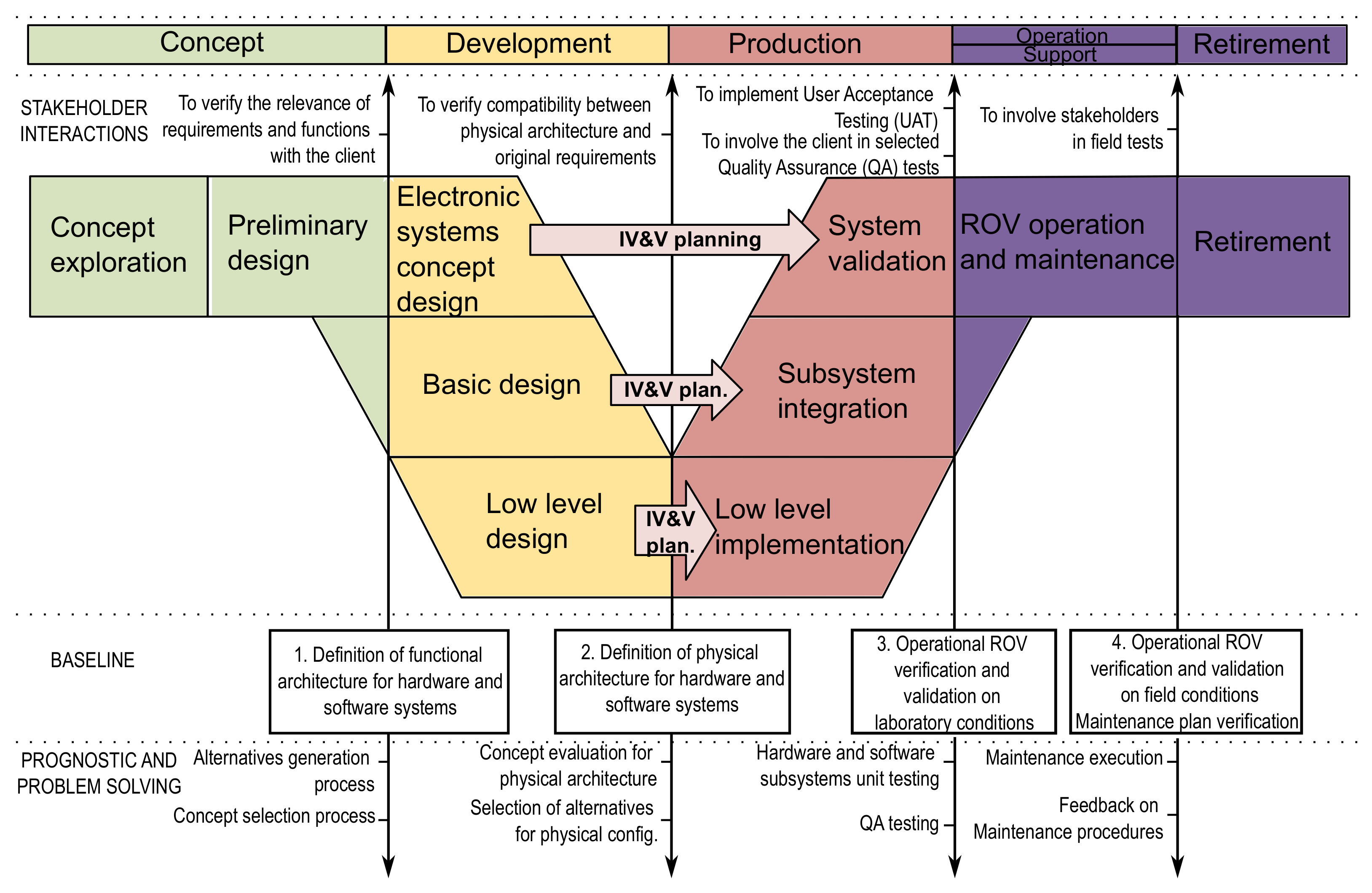
2.1. Vee Model
2.2. Baselines
2.3. Integration, Verification and Validation (IV&V)
3. Conceptual Design
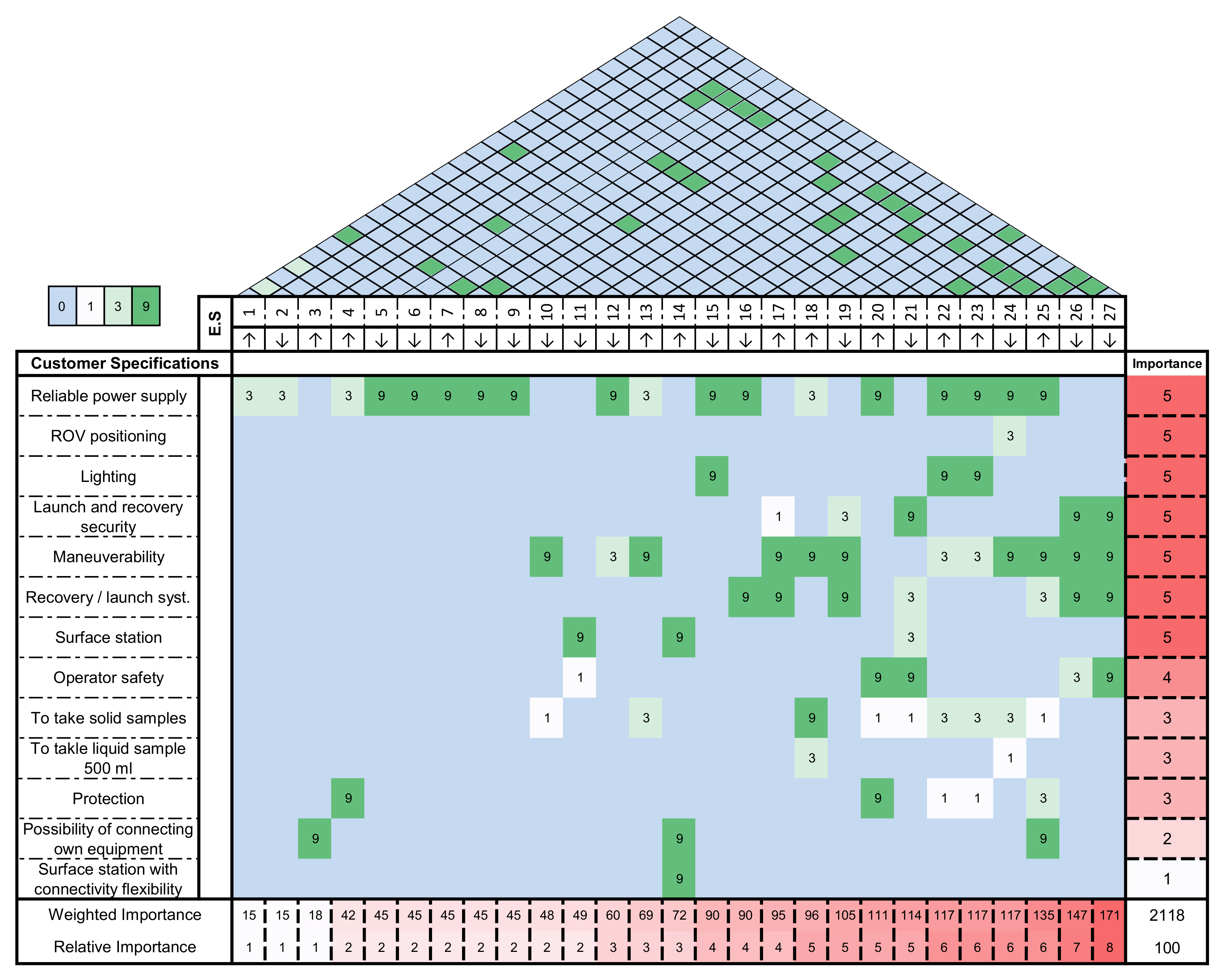
- Power system autonomy time.
- Average current (and range) of electrical power transmission
- Number of additional ports for connecting auxiliary equipment
- Energy storage capacity in the vehicle
- Power consumed by the propulsion system
- Supply voltage
- Maximum consumption current allowed
- Number of devices required for the power supply system
- Nominal power transmission voltage
- Control system response time
- Surface station size
- Average power demanded by the system
- Longitudinal advance thrust
- Additional ports available on the surface for connecting devices
- Power consumed by the lighting system
- Power consumed by the launch/recovery system
- Cable length
- Up/down thrust
- Umbilical cable gauge
- Existence of an electrical protection system
- Number of people needed to operate the system
- Number of lights
- Total illumination intensity
- Total number of thrusters
- Power (capacity/required availability) supply
- Vehicle dimensions
- Vehicle weight in air
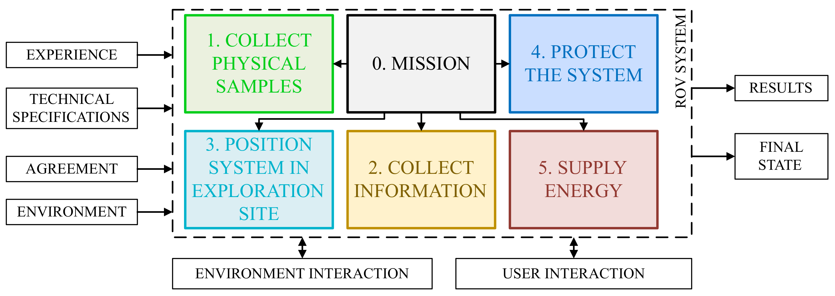
3.1. Functional Architecture
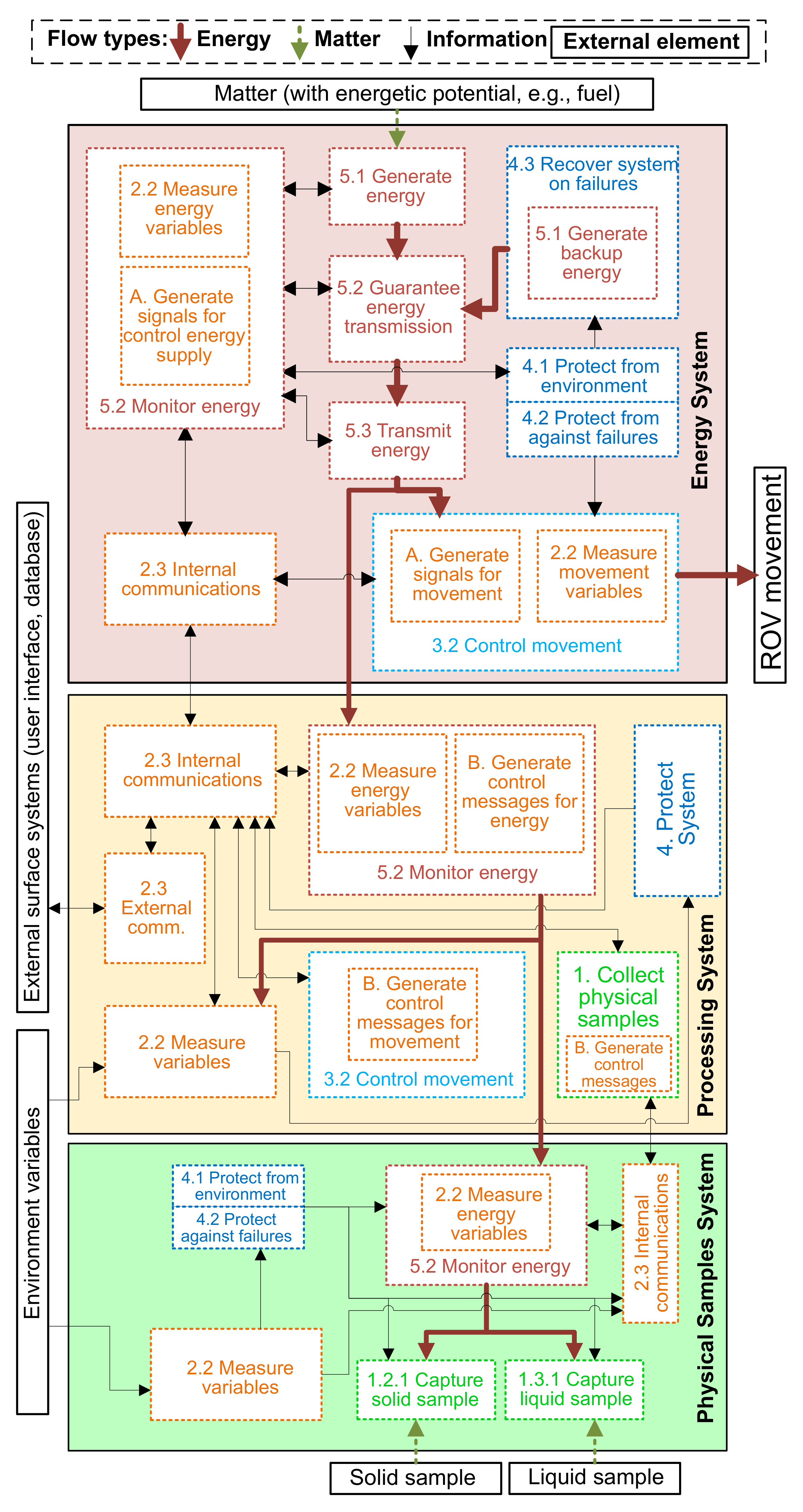
3.2. Hardware Architecture Definition
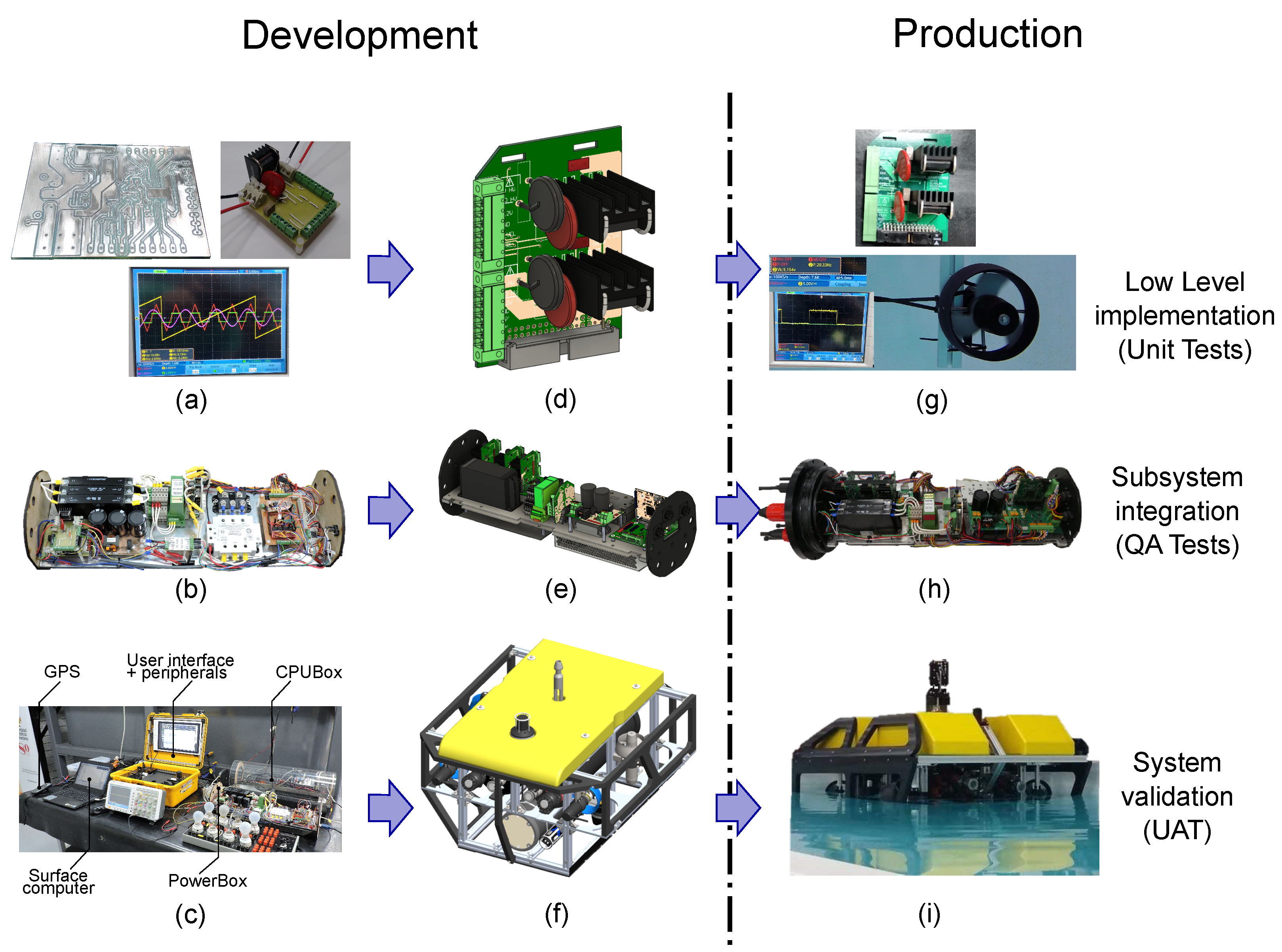
4. Development Stage
4.1. Hardware Architecture
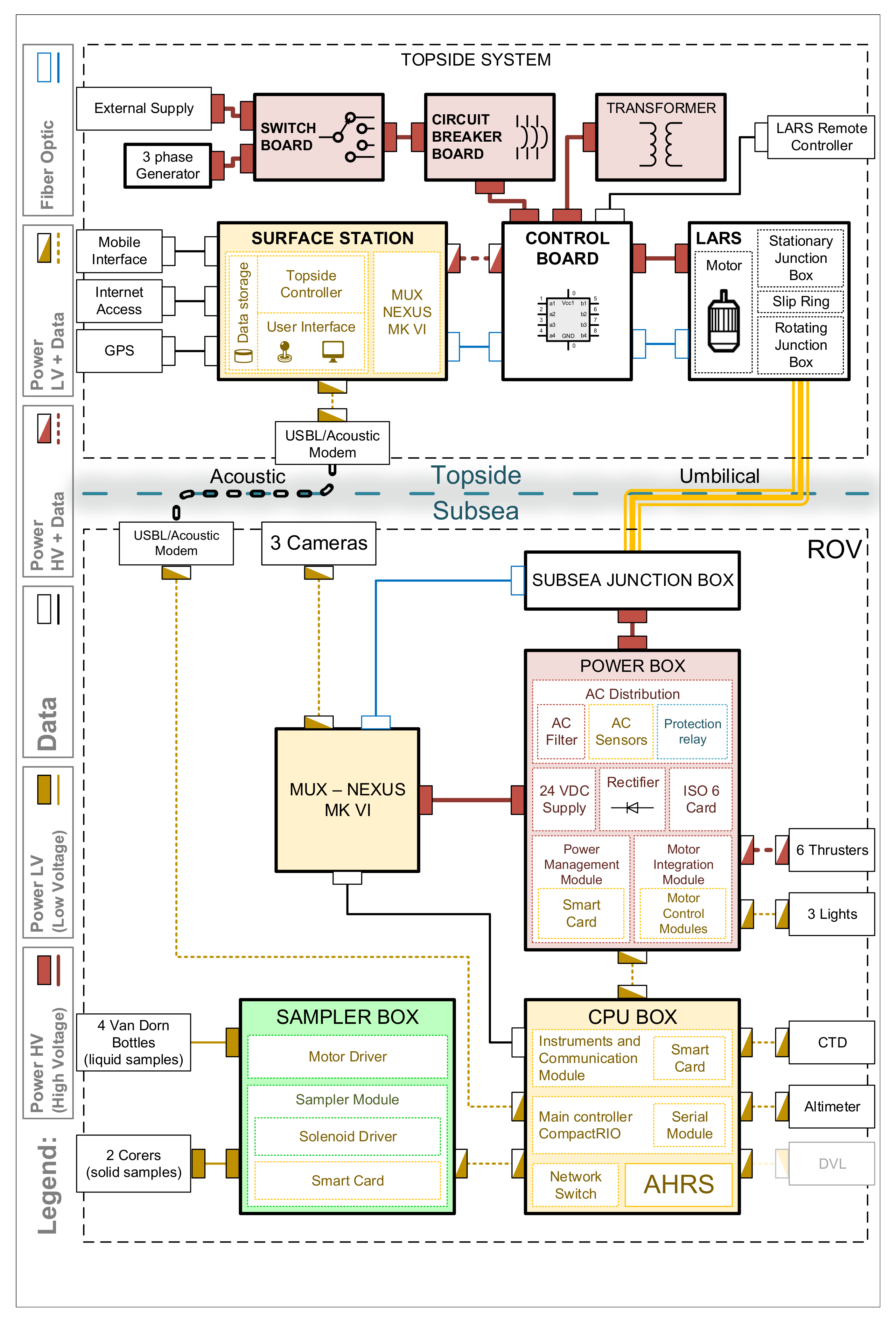
4.1.1. Subsea Systems
- The Power Box implements the Energy System’s functions (Figure 4), serving as a power hub that receives three-phase voltage signals from the Junction Box; then, it regulates, distributes and monitors power signals to other boxes and its own components. The Multiplexer Box is the only one that requires alternating current (AC) signals for operation. Other boxes operate on 24 VDC, such as the CPU Box and the Sampler Box. The Power Box manages low-level control and power signal generation for thrusters and lights. Regarding thrust power requirements, the acquired thrusters for Pionero500 operate on 260 VDC. To obtain this voltage level, three-phase AC voltage is rectified using a full-wave rectifier. Then, a motor integration module distributes it to each thruster. The thrusters are vulnerable to ground loop currents that can damage their internal electronics, so an OEM isolation module (ISO-6) was included to guarantee safe electrical operation conditions. Finally, a power management module was developed for low-voltage power signal monitoring and distribution to the rest of the vehicle.
- Multiplexer Box is an Original Equipment Manufacturer (OEM) device, commercially available from MacArtney. It is in charge of communication through a single fiber-optic cable, transmitting three high-definition video signals, a gigabit Ethernet data link for ROV control and box status signals and sensors.
- CPU Box is the main processing module of the vehicle. It contains a processor with a real-time operating system (RTOS) that communicates with the topside systems using a gigabit Ethernet data link. The software developed for vehicle operation follows the same modularity principle, leveraging the RTOS capabilities to implement every processing requirement of the existing modules, while allowing further functionality to be implemented seamlessly. In this box, instruments integration occurs. Minimal required instruments for the ROV operation include: Attitude and Heading and Reference System (AHRS), Conductivity-Temperature-Depth (CTD), altimeter, and Ultra Short Baseline (USBL).
- The Sampler Box is in charge of operating sediment and liquid samplers for Pionero500. Other boxes can be implemented to add functions to the vehicle, as long as the design complies with power and data interfaces restrictions.
4.1.2. Umbilical
4.1.3. Topside Systems
4.1.4. IV&V Activities
5. Production Stage
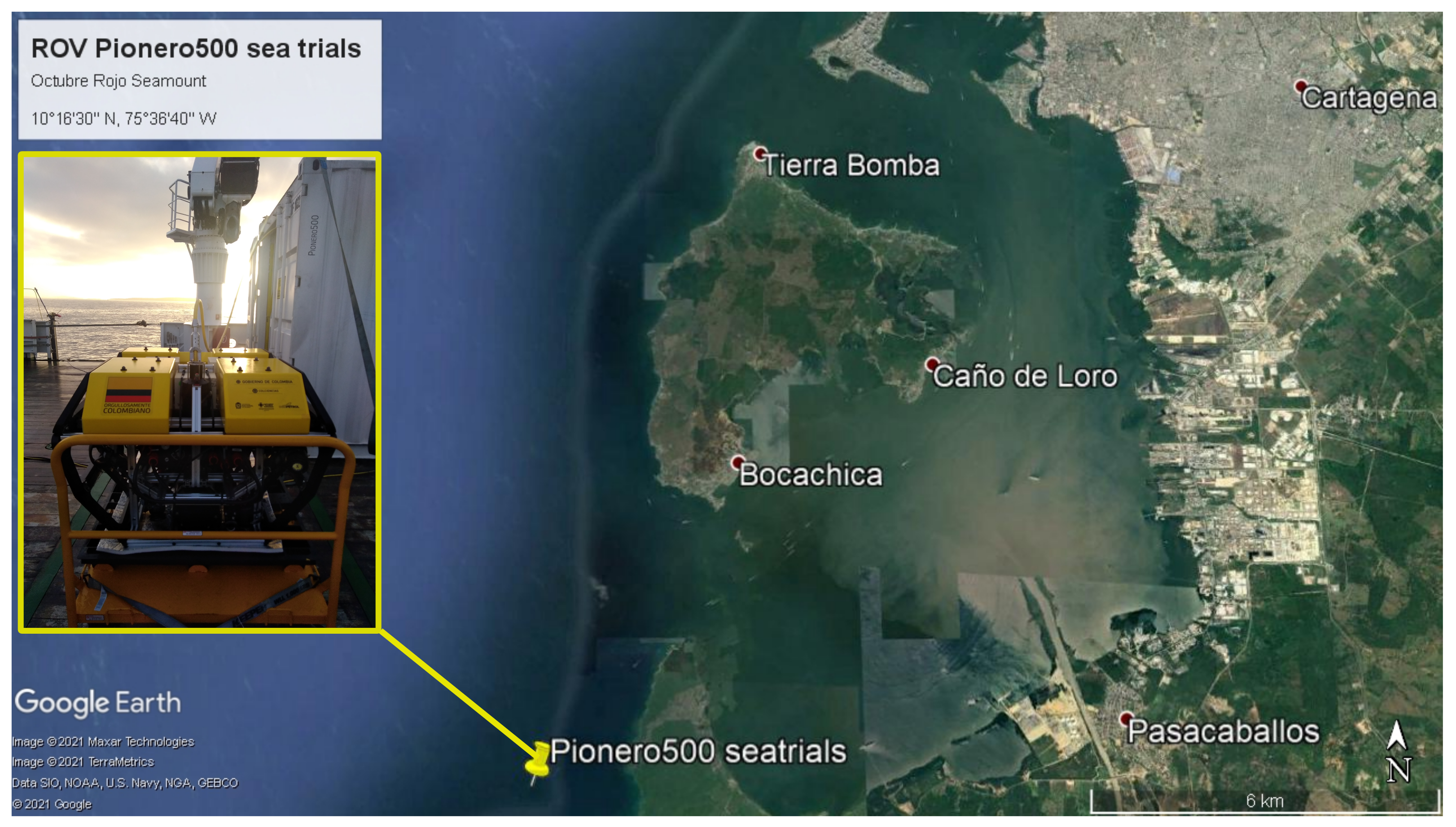
6. Operational Stage
7. Conclusions
Author Contributions
Funding
Institutional Review Board Statement
Informed Consent Statement
Conflicts of Interest
Abbreviations
| AC | Alternating Current |
| AHRS | Attitude and Heading and Reference System |
| AUV | Autonomous Underwater Vehicle |
| CAD | Computer Aided Design |
| CNC | Computer Numerical Control |
| COTS | Commercial Off-The-Shelf |
| CTD | Conductivity-Temperature-Depth |
| DAC | Digital to Analog Converter |
| ES | Engineering Specifications |
| GPS | Global Positioning System |
| GUI | Graphical User Interface |
| HoQ | House of Quality |
| IV&V | Integration, Verification and Validation |
| LARS | Launch and Recovery System |
| QA | Quality Assurance |
| OEM | Original Equipment Manufacturer |
| QFD | Quality Function Deployment |
| ROV | Remotely Operated Vehicle |
| RTOS | Real-time operating system |
| SE | Systems Engineering |
| UAT | User Acceptance Tests |
| UPS | Uninterrumpted Power Supply |
| USBL | Ultra Short Baseline |
| USV | Unmanned Surface Vehicle |
| UUV | Unmanned Underwater Vehicle |
| VDC | Volts of Direct Current |
References
- Macreadie, P.I.; McLean, D.L.; Thomson, P.G.; Partridge, J.C.; Jones, D.O.; Gates, A.R.; Benfield, M.C.; Collin, S.P.; Booth, D.J.; Smith, L.L.; et al. Eyes in the sea: Unlocking the mysteries of the ocean using industrial, remotely operated vehicles (ROVs). Sci. Total. Environ. 2018, 634, 1077–1091. [Google Scholar] [CrossRef]
- Capocci, R.; Dooly, G.; Omerdić, E.; Coleman, J.; Newe, T.; Toal, D. Inspection-Class Remotely Operated Vehicles—A Review. J. Mar. Sci. Eng. 2017, 5, 13. [Google Scholar] [CrossRef]
- Choi, J.; Park, J.; Jung, J.; Lee, Y.; Choi, H.T. Development of an Autonomous Surface Vehicle and Performance Evaluation of Autonomous Navigation Technologies. Int. J. Control. Autom. Syst. 2020, 18, 535–545. [Google Scholar] [CrossRef]
- Ramírez-Macías, J.A.; Vásquez, R.E.; Sørensen, A.J.; Sævik, S. Motion Feasibility Framework for Remotely Operated Vehicles Based on Dynamic Positioning Capability. J. Offshore Mech. Arct. Eng. 2021, 143. [Google Scholar] [CrossRef]
- Yao, H.; Wang, H.; Li, Y.; Wang, Y.; Han, C. Research on Unmanned Underwater Vehicle Threat Assessment. IEEE Access 2019, 7, 11387–11396. [Google Scholar] [CrossRef]
- Braginsky, B.; Baruch, A.; Guterman, H. Development of an Autonomous Surface Vehicle capable of tracking Autonomous Underwater Vehicles. Ocean. Eng. 2020, 197, 106868. [Google Scholar] [CrossRef]
- Smolyaninov, I.; Balzano, Q.; Young, D. Development of Broadband Underwater Radio Communication for Application in Unmanned Underwater Vehicles. J. Mar. Sci. Eng. 2020, 8, 370. [Google Scholar] [CrossRef]
- Zolich, A.; Johansen, T.A.; Cisek, K.; Klausen, K. Unmanned aerial system architecture for maritime missions. design & hardware description. In Proceedings of the 2015 Workshop on Research, Education and Development of Unmanned Aerial Systems (RED-UAS) IEEE, Cancun, Mexico, 23–25 November 2015. [Google Scholar] [CrossRef]
- Sulligoi, G.; Vicenzutti, A.; Menis, R. All-Electric Ship Design: From Electrical Propulsion to Integrated Electrical and Electronic Power Systems. IEEE Trans. Transp. Electrif. 2016, 2, 507–521. [Google Scholar] [CrossRef]
- Hachicha, S.; Zaoui, C.; Dallagi, H.; Nejim, S.; Maalej, A. Innovative design of an underwater cleaning robot with a two arm manipulator for hull cleaning. Ocean Eng. 2019, 181, 303–313. [Google Scholar] [CrossRef]
- Saravanan, K.; Aswini, S.; Kumar, R.; Son, L.H. How to prevent maritime border collision for fisheries?-A design of Real-Time Automatic Identification System. Earth Sci. Inform. 2019, 12, 241–252. [Google Scholar] [CrossRef]
- Ma, T.; Liu, S.; Xiao, H. Location of natural gas leakage sources on offshore platform by a multi-robot system using particle swarm optimization algorithm. J. Nat. Gas Sci. Eng. 2020, 84, 103636. [Google Scholar] [CrossRef]
- Utter, B.; Brown, A. Open-source five degree of freedom motion platform for investigating fish-robot interaction. HardwareX 2020, 7, e00107. [Google Scholar] [CrossRef]
- Ribas, D.; Ridao, P.; Turetta, A.; Melchiorri, C.; Palli, G.; Fernandez, J.J.; Sanz, P.J. I-AUV Mechatronics Integration for the TRIDENT FP7 Project. IEEE/ASME Trans. Mechatron. 2015, 20, 2583–2592. [Google Scholar] [CrossRef]
- Spears, A.; West, M.; Meister, M.; Buffo, J.; Walker, C.; Collins, T.R.; Howard, A.; Schmidt, B. Under Ice in Antarctica: The Icefin Unmanned Underwater Vehicle Development and Deployment. IEEE Robot. Autom. Mag. 2016, 23, 30–41. [Google Scholar] [CrossRef]
- Jiang, C.M.; Wan, L.; Sun, Y.S. Design of motion control system of pipeline detection AUV. J. Cent. South Univ. 2017, 24, 637–646. [Google Scholar] [CrossRef]
- Li, Y.; Guo, S.; Wang, Y. Design and characteristics evaluation of a novel spherical underwater robot. Robot. Auton. Syst. 2017, 94, 61–74. [Google Scholar] [CrossRef]
- Gelli, J.; Meschini, A.; Monni, N.; Pagliai, M.; Ridolfi, A.; Marini, L.; Allotta, B. Development and Design of a Compact Autonomous Underwater Vehicle: Zeno AUV. IFAC-PapersOnLine 2018, 51, 20–25. [Google Scholar] [CrossRef]
- Pugi, L.; Allotta, B.; Pagliai, M. Redundant and reconfigurable propulsion systems to improve motion capability of underwater vehicles. Ocean Eng. 2018, 148, 376–385. [Google Scholar] [CrossRef]
- Hong, S.; Chung, D.; Kim, J.; Kim, Y.; Kim, A.; Yoon, H.K. In-water visual ship hull inspection using a hover-capable underwater vehicle with stereo vision. J. Field Robot. 2018, 36, 531–546. [Google Scholar] [CrossRef]
- Costa, D.; Palmieri, G.; Palpacelli, M.C.; Panebianco, L.; Scaradozzi, D. Design of a Bio-Inspired Autonomous Underwater Robot. J. Intell. Robot. Syst. 2018, 91, 181–192. [Google Scholar] [CrossRef]
- Ignacio, L.C.; Victor, R.R.; Francisco, D.R.R.; Pascoal, A. Optimized design of an autonomous underwater vehicle, for exploration in the Caribbean Sea. Ocean Eng. 2019, 187, 106184. [Google Scholar] [CrossRef]
- Xu, H.; Zhang, G.C.; Sun, Y.S.; Pang, S.; Ran, X.R.; Wang, X.B. Design and Experiment of a Plateau Data-Gathering AUV. J. Mar. Sci. Eng. 2019, 7, 376. [Google Scholar] [CrossRef]
- Cozijn, H.; van der Schaaf, H.; de Kruif, B.; Ypma, E. Design of an Underwater Vehicle for use in Basin Experiments, Development of MARIN’s Modular AUV. IFAC-PapersOnLine 2019, 52, 21–26. [Google Scholar] [CrossRef]
- Pinjare, N.S.; Chaitra, S.; Shraavan, S.; Harshita; Naveen, I.G. Underwater remotely operated vehicle for surveillance and marine study. In Proceedings of the 2017 International Conference on Electrical, Electronics, Communication, Computer, and Optimization Techniques (ICEECCOT) IEEE, Mysuru, India, 15–16 December 2017. [Google Scholar] [CrossRef]
- Capocci, R.; Omerdic, E.; Dooly, G.; Toal, D. Fault-Tolerant Control for ROVs Using Control Reallocation and Power Isolation. J. Mar. Sci. Eng. 2018, 6, 40. [Google Scholar] [CrossRef]
- Rozman, B.Y.; Elkin, A.V.; Kaptsov, A.S.; Ermakov, I.D.; Ermakov, D.I.; Krasnov, V.G.; Kondrashov, L.S. Upgrade of ROV Super GNOME Pro for Underwater Monitoring in the Caspian Sea. Oceanology 2018, 58, 144–147. [Google Scholar] [CrossRef]
- Zhang, Q.; Wang, H.; Li, B.; Cui, S.; Zhao, Y.; Zhu, P.; Sun, B.; Zhang, Z.; Li, Z.; Li, S. Development and Sea Trials of a 6000m Class ROV for Marine Scientific Research. In Proceedings of the 2018 OCEANS - MTS/IEEE Kobe Techno-Oceans (OTO) IEEE, Kobe, Japan, 28–31 May 2018. [Google Scholar] [CrossRef]
- Kadiyam, J.; Mohan, S. Conceptual design of a hybrid propulsion underwater robotic vehicle with different propulsion systems for ocean observations. Ocean Eng. 2019, 182, 112–125. [Google Scholar] [CrossRef]
- Kong, F.; Guo, Y.; Lyu, W. Dynamics Modeling and Motion Control of an New Unmanned Underwater Vehicle. IEEE Access 2020, 8, 30119–30126. [Google Scholar] [CrossRef]
- Madni, A.M.; Sievers, M. Systems Integration: Key Perspectives, Experiences, and Challenges. Syst. Eng. 2013, 17, 37–51. [Google Scholar] [CrossRef]
- Madni, A.M.; Sievers, M. Model-based systems engineering: Motivation, current status, and research opportunities. Syst. Eng. 2018, 21, 172–190. [Google Scholar] [CrossRef]
- NASA. NASA Systems Engineering Handbook: NASA/SP-2016-6105 Rev2 - Full Color Version; 12th Media Services: Washington, DC, USA, 2017.
- Dove, R.; Schindel, B.; Scrapper, C. Agile Systems Engineering Process Features Collective Culture, Consciousness, and Conscience at SSC Pacific Unmanned Systems Group. INCOSE Int. Symp. 2016, 26, 982–1001. [Google Scholar] [CrossRef]
- Eaton, C.; Chong, E.; Maciejewski, A. Multiple-Scenario Unmanned Aerial System Control: A Systems Engineering Approach and Review of Existing Control Methods. Aerospace 2016, 3, 1. [Google Scholar] [CrossRef]
- Hien, N.V.; Truong, V.T.; Bui, N.T. An Object-Oriented Systems Engineering Point of View to Develop Controllers of Quadrotor Unmanned Aerial Vehicles. Int. J. Aerosp. Eng. 2020, 2020, 1–17. [Google Scholar] [CrossRef]
- Weinert, B.; Hahn, A.; Norkus, O. A domain-specific architecture framework for the maritime domain. In Informatik 2016, P-259 ed.; Lecture Notes in Informatics; Heinrich, C., Mayr, M.P., Eds.; Gesellschaft für Informatik: Boon, Germany, 2016. [Google Scholar]
- Freire, L.O.; Oliveira, L.M.; Vale, R.T.; Medeiros, M.; Diana, R.E.; Lopes, R.M.; Pellini, E.L.; de Barros, E.A. Development of an AUV control architecture based on systems engineering concepts. Ocean Eng. 2018, 151, 157–169. [Google Scholar] [CrossRef]
- Huang, P.M.; Darrin, A.G.; Knuth, A.A. Agile hardware and software system engineering for innovation. In Proceedings of the 2012 IEEE Aerospace Conference IEEE, Big Sky, MT, USA, 3–10 March 2012. [Google Scholar] [CrossRef]
- Chennareddy, S.S.R.; Agrawal, A.; Karuppiah, A. Modular Self-Reconfigurable Robotic Systems: A Survey on Hardware Architectures. J. Robot. 2017, 2017, 1–19. [Google Scholar] [CrossRef]
- Zamalloa, I.; Muguruza, I.; Hernández, A.; Kojcev, R.; Mayoral, V. An information model for modular robots: The Hardware Robot Information Model (HRIM). Technical report, Erle Robotics. arXiv 2018, arXiv:1802.01459. [Google Scholar]
- Seo, J.; Paik, J.; Yim, M. Modular Reconfigurable Robotics. Annu. Rev. Control. Robot. Auton. Syst. 2019, 2, 63–88. [Google Scholar] [CrossRef]
- Gharbia, M.; Chang-Richards, A.; Lu, Y.; Zhong, R.Y.; Li, H. Robotic technologies for on-site building construction: A systematic review. J. Build. Eng. 2020, 32, 101584. [Google Scholar] [CrossRef]
- Giordano, F.; Mattei, G.; Parente, C.; Peluso, F.; Santamaria, R. Integrating Sensors into a Marine Drone for Bathymetric 3D Surveys in Shallow Waters. Sensors 2015, 16, 41. [Google Scholar] [CrossRef]
- Sarhadi, P.; Noei, A.R.; Khosravi, A. Model reference adaptive autopilot with anti-windup compensator for an autonomous underwater vehicle: Design and hardware in the loop implementation results. Appl. Ocean. Res. 2017, 62, 27–36. [Google Scholar] [CrossRef]
- Meschini, A.; Ridolfi, A.; Gelli, J.; Pagliai, M.; Rindi, A. Pressure Hull Design Methods for Unmanned Underwater Vehicles. J. Mar. Sci. Eng. 2019, 7, 382. [Google Scholar] [CrossRef]
- Sani, M.I.; Siregar, S.; Kurnia, M.M.; Hasbialloh, D. An electrical power control system for explorer-class remotely operated underwater vehicle (ROV). TELKOMNIKA (Telecommun. Comput. Electron. Control.) 2019, 17, 928. [Google Scholar] [CrossRef]
- Sun, Y.; Ran, X.; Zhang, G.; Wu, F.; Du, C. Distributed control system architecture for deep submergence rescue vehicles. Int. J. Nav. Archit. Ocean. Eng. 2019, 11, 274–284. [Google Scholar] [CrossRef]
- Yu, C.; Xiang, X.; Maurelli, F.; Zhang, Q.; Zhao, R.; Xu, G. Onboard system of hybrid underwater robotic vehicles: Integrated software architecture and control algorithm. Ocean Eng. 2019, 187, 106121. [Google Scholar] [CrossRef]
- Odetti, A.; Bruzzone, G.; Altosole, M.; Viviani, M.; Caccia, M. SWAMP, an Autonomous Surface Vehicle expressly designed for extremely shallow waters. Ocean Eng. 2020, 216, 108205. [Google Scholar] [CrossRef]
- Bae, J.H.; Min, B.C.; Luo, S.; Kannan, S.S.; Singh, Y.; Lee, B.; Voyles, R.M.; Postigo-Malaga, M.; Zenteno, E.G.; Aguilar, L.P.; et al. Development of an Unmanned Surface Vehicle for Remote Sediment Sampling with a Van Veen Grab Sampler. In Proceedings of the OCEANS 2019 MTS/IEEE SEATTLE IEEE, Seattle, WA, USA, 27–31 October 2019. [Google Scholar] [CrossRef]
- Peeters, G.; Baelen, S.V.; Yayla, G.; Catoor, T.; Afzal, M.R.; Christofakis, C.; Louw, R.; Singh, Y.; Vanierschot, M.; Boonen, R.; et al. Decoupled Hydrodynamic Models and Their Outdoor Identification for an Unmanned Inland Cargo Vessel with Embedded Fully Rotatable Thrusters. J. Mar. Sci. Eng. 2020, 8, 889. [Google Scholar] [CrossRef]
- Aristizabal, L.M.; Rua, S.; Zuluaga, C.A.; Posada, N.L.; Vasquez, R.E. Hardware and software development for the navigation, guidance, and control system of a remotely operated vehicle. In Proceedings of the 2017 IEEE 3rd Colombian Conference on Automatic Control (CCAC) IEEE, Cartagena, Colombia, 18–20 October 2017. [Google Scholar] [CrossRef]
- Dieter, G.; Schmidt, L. Engineering Design, 6th ed.; McGraw-Hill Education: New York, NY, USA, 2021. [Google Scholar]
- INCOSE. INCOSE Systems Engineering Handbook: A Guide for System Life Cycle Processes and Activities, 4th ed.; Wiley: Hoboken, NJ, USA, 2015. [Google Scholar]
- Forsberg, K.; Mooz, H.; Cotterman, H. Visualizing Project Management: Models and Frameworks for Mastering Complex Systems, 3rd ed.; J. Wiley: Hoboken, NJ, USA, 2005. [Google Scholar]
- Federal Highway Administration California Division. Systems Engineering Guidebook for Intelligent Transportation Systems, 3rd ed.; US Department of Transportation: Washington, DC, USA, 2009.
- Ullman, D. The Mechanical Design Process, 6th ed.; David Ullman LLC: Independence, OR, USA, 2017. [Google Scholar]
- ISO/IEC/IEEE. 15288-2015 - ISO/IEC/IEEE International Standard - Systems and Software Engineering—System Life Cycle Processes, 1st ed.; IEEE: Piscataway, NJ, USA, 2015. [Google Scholar] [CrossRef]
- Osorio, S.P.; Aristizabal, L.M.; Zuluaga, C.A. Development of a command interface based on handheld devices for remotely operated vehicles. In Proceedings of the 2016 IEEE Colombian Conference on Robotics and Automation (CCRA) IEEE, Bogota, Colombia, 29–30 September 2016. [Google Scholar] [CrossRef]


Publisher’s Note: MDPI stays neutral with regard to jurisdictional claims in published maps and institutional affiliations. |
© 2021 by the authors. Licensee MDPI, Basel, Switzerland. This article is an open access article distributed under the terms and conditions of the Creative Commons Attribution (CC BY) license (https://creativecommons.org/licenses/by/4.0/).
Share and Cite
Aristizábal, L.M.; Zuluaga, C.A.; Rúa, S.; Vásquez, R.E. Modular Hardware Architecture for the Development of Underwater Vehicles Based on Systems Engineering. J. Mar. Sci. Eng. 2021, 9, 516. https://doi.org/10.3390/jmse9050516
Aristizábal LM, Zuluaga CA, Rúa S, Vásquez RE. Modular Hardware Architecture for the Development of Underwater Vehicles Based on Systems Engineering. Journal of Marine Science and Engineering. 2021; 9(5):516. https://doi.org/10.3390/jmse9050516
Chicago/Turabian StyleAristizábal, Luis M., Carlos A. Zuluaga, Santiago Rúa, and Rafael E. Vásquez. 2021. "Modular Hardware Architecture for the Development of Underwater Vehicles Based on Systems Engineering" Journal of Marine Science and Engineering 9, no. 5: 516. https://doi.org/10.3390/jmse9050516
APA StyleAristizábal, L. M., Zuluaga, C. A., Rúa, S., & Vásquez, R. E. (2021). Modular Hardware Architecture for the Development of Underwater Vehicles Based on Systems Engineering. Journal of Marine Science and Engineering, 9(5), 516. https://doi.org/10.3390/jmse9050516