Article

Conformal Mapping-Based Discrete Vortex Method for Simulating 2-D Flows around Arbitrary Cylinders

1
School of Naval Architecture, Dalian University of Technology, Dalian 116024, China
2
State Key Laboratory of Structural Analysis for Industrial Equipment, Dalian 116024, China
*
Author to whom correspondence should be addressed.
J. Mar. Sci. Eng. 2021, 9(12), 1409; https://doi.org/10.3390/jmse9121409
Submission received: 20 November 2021 / Revised: 7 December 2021 / Accepted: 7 December 2021 / Published: 10 December 2021

Abstract

:
A novel technique based on conformal mapping and the circle theorem has been developed to tackle the boundary penetration issue, in which vortex blobs leak into structures in two-dimensional discrete vortex simulations, as an alternative to the traditional method in which the blobs crossing the boundary are simply removed from the fluid field or reflected back to their mirror-image positions outside the structure. The present algorithm introduces an identical vortex blob outside the body using the mapping method to avoid circulation loss caused by the vortex blob penetrating the body. This can keep the body surface streamlined and guarantees that the total circulation will be constant at any time step. The model was validated using cases of viscous incompressible flow passing elliptic cylinders with various thickness-to-chord ratios at Reynolds numbers greater than Re = 1 × 10⁵. The force and velocity fields revealed that this boundary scheme converged, and the resultant time-averaged surface pressure distributions were all in excellent agreement with wind tunnel tests. Furthermore, a flow around a symmetrical Joukowski foil at Reynolds number Re = 4.62 × 10⁴, without considering the trailing cusp, was investigated, and a close agreement with the experimental data was obtained.

1. Introduction

The mesh-free discrete vortex method (DVM) developed by Chorin [1] is generally used to simulate incompressible viscous flows past structures under high Reynolds numbers. This issue is commonly encountered in ocean engineering, such as flows past marine risers, offshore platforms, and propellers, etc. It should be noted that most numerical investigations of flow over bodies are based on the meshing scheme and turbulence model; however, the grid resolution of the volume discretization method is generally not fine enough to capture the flow accurately [2,3]. Moreover, the quality of mesh has a serious influence on computational fluid simulation, especially at high Re. However, the discrete vortex method overcomes the aforementioned limitations of the meshing scheme; in particular, it is commonly useful for solving the flow separation problem of flow past a bluff body [4,5]. As a mesh-free method, particles automatically accumulate near the body surface and local area containing the vortex structures, which results in relatively low computational costs [5]. Investigations on flow around bluff bodies have been extensively carried out [6]—especially flow around circular cylinders, which is accompanied by rich flow phenomena and is commonly regarded as a benchmark case.
Recent progress in the development of discrete vortex methods has particularly concentrated on improvements in the accuracy of numerical results and the high resolution of wake fields [7,8,9,10,11,12,13,14,15,16]. Some of the literature has also focused on the extension of the vortex method, such as solving structural deformations via coupling with the finite element method [17,18,19,20,21]. In vortex methods, vortices already in the fluid can leak into the body owing to random walk, which causes serious damage to the streamlined body surface. Therefore, the boundary method is employed to maintain the no-penetration boundary condition; furthermore, the accuracy of the solution can be enhanced. Several heuristic boundary algorithms have been proposed to tackle this problem. Chorin [1,22] indicated that any particles which cross the body surface can be removed from the calculation, and that lost circulation is regenerated during the next iteration, which guarantees the conservation of all vortex strengths over the entire simulation. A large bulk of literature [23,24,25,26] uses this approach to deal with vortices penetrating the surface. Notice that the above vortex elimination method cannot conserve the total circulation of elements in the fluid domain. As a result, this brings about a reduction in the numerical precision of fluid forces acting on the body. This boundary method has been further investigated by Smith et al. [27,28], where they used an efficient, improved algorithm involving the correction of the vortex strength. Another boundary method has been employed by Chorin [29] and Ghoniem et al. [30], where elements leaking into the structure need to be mapped across the nearest wall to their mirror-image locations in the fluid domain, without changing their strengths. However, this scheme cannot keep the surface streamlined for common bodies with large curvature.
Instead of the algorithms mentioned above, Pang et al. [31,32] have presented instantaneous vorticity conserved boundary conditions (IVCBC) to address elements inside structures using the circle theorem technique [4]. This algorithm ensures that the total circulation of vortex blobs is conserved at any time step, and it can keep the streamlined surface non-destructive. Flows over circular cylinders, based on the vortex method with the IVCBC scheme, have been discussed by Pang [31], who made an effort to improve the precision of the vortex method. However, this improved scheme can only be employed in the specific situation of flows around circular cylinders, due to the employment of the circle theorem. Accordingly, the use of conformal mapping and the circle theorem for simulation of flows around arbitrary cylinders has been considered.
In this paper, a novel algorithm has been developed to handle vortex blobs entering an elliptic cylinder using conformal mapping and the circle theorem. This study provides a detailed description of this new scheme and its numerical implementation. We first calculated the flow past a circular cylinder at Re = 1.4 × 10⁵, based on the IVCBC boundary scheme developed by Pang et al. [31]. Then, we performed simulations of viscous flow around a series of elliptic cylinders with various thickness-to-chord ratios at Reynolds numbers greater than 1 × 10⁵. In particular, the force and velocity fields were obtained. The predicted results coincided well with the experimental data for the time-average surface pressure distribution. Moreover, there was an improvement in the numerical results of fluid forces compared with previous vortex methods. As a natural extension to the research on Joukowski foils, this paper investigated the pressure distribution of a symmetrical Joukowski foil at Re = 4.62 × 10⁴, without regard to the trailing cusp, and a close agreement with the experimental data was also found by using the present boundary scheme. In practice, the present method can be used in flows over arbitrary sectional cylinders, although difficulties will be encountered in the approach when trying to obtain conformal transformations for complicated geometries.

2. Fundamentals of the DVM

2.1. Governing Equation

The problem of flow around elliptic cylinders was solved using the discrete vortex method, which is a pure Lagrangian numerical method for simulating viscous fluid flow [1]. Its governing equations are based on the continuity equation and the Navier–Stokes equation:
u = 0 .
D u D t = f 1 ρ p + ν 2 u
where u represents the velocity vector, f denotes the mass force, ρ is the fluid density, p denotes the pressure, t is the time, and ν represents the fluid kinematic viscosity. Taking the curl on two sides of Equation (2), the vorticity transport equation can be determined in a 2-D framework, that is:
ω t + ( u ) ω = ν 2 ω .
where ω represents the vorticity perpendicular to the 2-D plane, that is:
ω = v x u y .
where u and v denote the velocities in the x and y directions, respectively. The velocity components can be solved by u = ψ / y and v = ψ / x , where ψ represents the stream function. Substituting u and v into Equation (4), the Poisson equation can be obtained:
2 ψ = ω .
The operator splitting technique proposed by Chorin [1] was used to solve the above governing equations. Equation (3) can be divided into two parts:
The convection governing equation is:
ω t = u ω , 2 ψ = ω .
The viscous diffusion equation is:
ω t = ν 2 ω .

2.2. Numerical Implementation

In the DVM, nascent vortex blobs are created near the structural surface. Then, these elements are moved into the wake flow field by convection and diffusion. The boundary is discretized in N segments with the same length Δ s . The i -th vortex blob ( 1 i N ) is generated in the normal direction n i from the midpoint of the i -th segment, where the midpoint is called a control point. The radius σ of nascent vortex blobs is σ = Δ s / 2 π , which is employed by Chorin [1] and Wu [33]. Using a counter-clockwise surface point orientation, a sketch of boundary discretization is depicted in Figure 1.
The solution to Equation (6) was determined by the Biot–Savart law, and a vortex core model proposed by Spalart et al. [23] was used to smooth the velocity function. The convection velocity can be obtained by:
u ( z , t ) = u 1 2 π j = 1 N V z z j × k Γ j z z j 2 + σ 2 .
where u = ( u , 0 ) is the incoming velocity, z j = ( x j , y j ) and Γ j represent the position of the j -th vortex blob and the corresponding circulation, respectively, σ denotes the radius of vortex blobs, N V is the number of vortex blobs in the fluid field, and k is the unit vector in the out-of-plane direction.
The stream function is given by:
ψ = Γ 4 π ln ( z 2 + σ 2 ) .
The ψ for two adjacent control points satisfies the condition of Spalart et al. [34]:
ψ k + 1 ψ k = 0 .
An algebraic equation is determined through Equations (9) and (10) to solve the circulations of the nascent elements, that is:
A Γ = b .
where A is a ( N , N ) matrix, b is a vector, and Γ is the circulation vector; they can be expressed as:
A = a k i , a k i = 1 4 π ln ( x k + 1 x i ) 2 + ( y k + 1 y i ) 2 + σ 2 ( x k x i ) 2 + ( y k y i ) 2 + σ 2 .
b = b k , b k = u ( y k + 1 y k ) 1 4 π j = 1 M Γ j ln ( x k + 1 x j ) 2 + ( y k + 1 y j ) 2 + σ 2 ( x k x j ) 2 + ( y k y j ) 2 + σ 2 .
where the position ( x N + 1 , y N + 1 ) is equal to ( x 1 , y 1 ) , k = 1, 2, ..., N, and i = 1, 2, ..., N. The matrix A is related to the position of the nascent elements. The vector b is, therefore, associated with the elements in the fluid field. In addition, the conservation condition of total circulation [35] is:
i = 1 N Γ i = j = 1 M Γ j .
where i = 1 N Γ i and j = 1 M Γ j are the total circulation of the newly created vortex blobs and the wake elements, respectively. The circulations of nascent vortex blobs can be calculated using a combination of Equations (11) and (14). Therefore, Equation (11) can be converted into:
A Γ = b .
The new matrix A and vector b are given by:
A = a 1 , 1 a 1 , i a 1 , N a 2 , 1 a 2 , i a 2 , N a k , 1 a k , i a k , N a N , 1 a N , i a N , N 1 1 1 ,   b = b 1 b 2 b i b N j = 1 M Γ j .
In this study, the least square method and the Gauss elimination algorithm were employed to solve the over-determined matrix equation above.
Chorin [1] employed the random walk method to simulate viscous diffusion. The random displacements of the i -th vortex blob in both directions are:
Δ x i = 4 ν Δ t ln ( 1 / P i ) cos Q i , Δ y i = 4 ν Δ t ln ( 1 / P i ) sin Q i .
where Δ x i and Δ y i denote the random displacements, Δ t is a time step, P i and Q i are random numbers independently in the ranges ( 0 , 1 ) and ( 0 , 2 π ) , respectively. The above scheme is also called the random vortex method (RVM), and there has emerged several kinds of deterministic vortex method, such as the core spreading method [5], the particle strength exchange method [36,37], and the diffusion velocity method [38], etc.
To reduce the simulation cost, Spalart et al. [23] developed a vortex merging scheme. Two adjacent vortex blobs need to be merged when they are subject to:
Γ i Γ j Γ i + Γ j z i z j 2 ( D 0 + d i ) 3 / 2 ( D 0 + d j ) 3 / 2 < V 0 .
where d i and d j are the distances from z i and z j to the nearest structural surface. It can be found that merging is prone to occur if two weak vortices are close to each other and far from the body. D 0 is a merging governing parameter and V 0 is a tolerance. Spalart et al. [23] suggested that D 0 is around 5% of the characteristic length and V 0 is of the order 10 6 u . The position and strength of the new vortex blob after merging are:
z = z i Γ i + z j Γ j Γ i + Γ j , Γ = Γ i + Γ j .
The wall pressure can be calculated according to the rate of creation of vorticity [23]. We have:
1 ρ p s = 2 Γ s t .
where the left-hand side notation is the derivate of the pressure along the wall, and the right-hand side notation is the rate of creation of circulation per unit length and unit time.
The shear stress can be calculated by:
τ = μ d u s d n .
where μ denotes the dynamic viscosity and u s is the tangent velocity.
The global fluid forces acting on the body surface can be obtained by the integration of the wall pressure and shear force. The drag coefficient C D is expressed by:
C D = F D 1 2 ρ u 2 L .
where F D denotes drag force and L is the characteristic length in the in-line direction.
As discussed in the introduction, vortex blobs could penetrate the body surface following random walk, which can lead to failure to meet the no-penetration boundary condition. Therefore, previous studies [1] have removed vortex blobs leaking into the structure, with the lost circulation being regenerated in the next iteration, which is expressed as Equation (14). However, this strategy would ruin the streamlined surface and result in a large numerical error. Pang et al. [31] presented the IVCBC method to deal with vortex blobs crossing the surface. In this approach, a vortex blob leaking into a solid is mapped onto the fluid domain with the same strength by the circle theorem, rather than by its mirror image, which would lead to a change of position of this element. At each time step, this method can keep the body surface streamlined, and the total circulation is always equal to zero. Hence, the last component of vector b can be expressed as:
j = 1 M Γ j = 0 .
Additionally, the position z = ( x , y ) and circulation Γ of the newly introduced vortex blob can be determined through the circle theorem. These are given by:
x = R 2 x x 2 + y 2 , y = R 2 y x 2 + y 2 .
Γ = Γ .
where z and Γ represent the position and circulation of the corresponding vortex blob leaking into the solid, respectively, and R is the radius of the circular cylinder.

2.3. A Novel Boundary Scheme to Address Flow Past Elliptic Cylinders

As discussed above, some vortex blobs cross the body surface after the convection and random walk at each time step. As a result, the no-penetration condition is broken, due to the circulation lost from vortex blobs leaking into the cylinder. To avoid the loss of simulation accuracy, a new boundary scheme has been developed in this study to handle these vortices using the circle theorem and conformal mapping. The IVCBC method [31] was established using the circle theorem, which exhibits an excellent result in flow around a circular cylinder. Encouragingly, this method can be extended to other bodies of arbitrary shape by employing the conformal mapping technique. In the theory of 2-D potential flow, it is difficult to solve the complex potential using the theoretical approach directly; thus, conformal transformation was developed to overcome this limitation. By choosing an appropriate function, an inconvenient geometry in the physical plane ( z -plane) can be transformed into a corresponding circular cylinder in the auxiliary plane ( ζ -plane). The complex potential of flow past the corresponding circular cylinder can be determined conveniently, and then, the complex potential of flow past the original body can be calculated using inverse transformation. In particular, there exists the Joukowski transformation function for an elliptical cylinder, and thus, a corresponding boundary scheme is presented to deal with vortices crossing the elliptical cylinder surface.
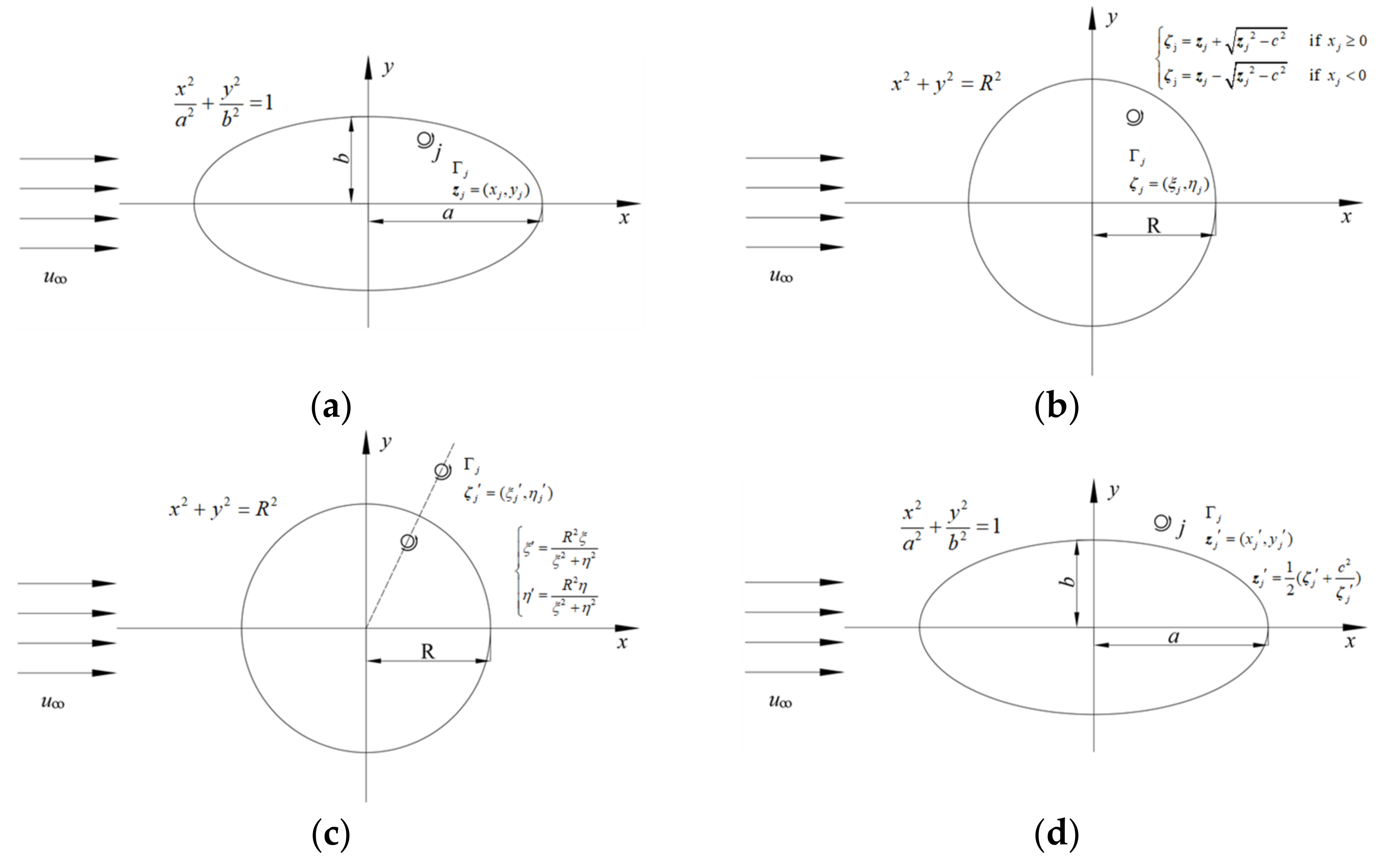
Consider a vortex blob j leaking into an elliptical cylinder at t moment (see Figure 2a); the corresponding position and the circulation are z j = x j + i y j and Γ j , respectively. The expression of an elliptical cylinder is given by:
x 2 a 2 + y 2 b 2 = 1 .
where a and b denote the lengths of the semimajor and semiminor axes of the elliptic cylinder, respectively. The elliptical cylinder can be transformed as a corresponding circular cylinder with a radius of R in the ζ -plane, where the radius can be obtained by:
R = a + b .
As shown in Figure 2b, the vortex blob j is mapped onto a circular cylinder in the auxiliary plane through the use of the inverse function of Joukowski transformation, which can be written as:
ζ j = z j + z j 2 c 2   if   x j 0 , ζ j = z j z j 2 c 2   if   x j < 0 .
where an additional constant c can be obtained by c 2 = a 2 b 2 , and ζ j = ξ + i η denotes the position of the transformed vortex blob in ζ -plane. The determination of the mapped equation depends on the abscissa value of the vortex blob j . The results of the calculation suggest that it can ensure that the vortex blob is located in the same quadrant before and after the mapping based on Equation (28), which is a significant finding in this study. This transformed element is located inside the circular cylinder, and so, we can then carry out a reflection for this element based on the circle theorem (see Figure 2c). It should be noted that the circulation and flow remain unchanged for a closed curve before and after conformal mapping, and thus, the strengths of vortex blobs should be identical after transformation or inverse transformation [4]. According to the core viewpoint of the IVCBC [31], an identical vortex blob is newly generated outside the cylinder, which guarantees that the boundary condition is met and that the total circulation is conserved. According to Equation (24), the position ζ j = ξ + i η of the image element can be given by:
ξ = R 2 ξ ξ 2 + η 2 , η = R 2 η ξ 2 + η 2 .
Furthermore, as depicted in Figure 2d, the image vortex blob outside the circular cylinder in the ζ -plane will be transformed outside the elliptic cylinder in the z -plane using the Joukowski function, which can be expressed as:
z j = 1 2 ( ζ j + c 2 ζ j ) .
Γ j = Γ j .
where z j = x j + i y j denotes the position of the newly introduced vortex blob, which has the same circulation as the original element in the z -plane. Additionally, the vortex blobs moving into the body need to be eliminated in this time step. Therefore, it can be seen that the new scheme implemented a redistribution of elements near the surface at each time step. In this study, only a few vortex blobs leaking into the structure needed to be considered; therefore, the calculation cost was low in employing the above algorithm.
To the best of our knowledge, there exists the same conformal mapping function with the elliptical cylinder as for the Joukowski foil, namely, the Joukowski transformation function. Considering this, we can adopt this novel scheme to simulate flow past a Joukowski foil at a high Reynolds number. It should be noted that the corresponding circular cylinder in the ζ -plane is eccentric.

3. Results and Discussion

Systematic numerical simulations for flow around elliptic cylinders with various thickness-to-chord ratios at high Re were conducted to validate the new boundary scheme of DVM, and the results were compared with wind tunnel experimental data. Additionally, some previous calculations based on DVM were also compared with our simulation to validate its improved effects. We first consider an elliptic cylinder with a thickness-to-chord ratio e = 0.16 (where e is a ratio of the semiminor axis to the semimajor axis, that is, e = b / a ) at the Reynolds number R e = 3 × 10 5 (where R e is given by R e = u L / ν , L is the characteristic dimension of the body parallel to the fluid direction, and L = 2 a for an elliptic cylinder) to investigate the sensitivity of the numerical parameters, including the number of nascent elements and the time-step size. Moreover, the influence of the vortex merging technique on numerical solutions was discussed. Then, a numerical simulation for flow past a circular cylinder at R e = 1.4 × 10 5 was conducted based on the IVCBC method [31]. In fact, the present method can be regarded as an extension of the IVCBC method. Furthermore, extensive simulations with various elliptic cylinders were conducted and compared with the results of the wind tunnel tests. At last, the flow past a symmetrical Joukowski foil at an angle of attack of 0° with R e = 4.62 × 10 4 was simulated. When solving the time-averaging forces, a normalized time t = t u / L was employed. It should be noted that the length L is the chord length for the Joukowski foil.

3.1. Sensitivity Analysis of Numerical Parameters

We first discuss the influence on the accuracy of the solution of the time step and the number of nascent vortex blobs, where the latter is equal to the number of segments N . In the previous literature, the determination of the time step Δ t generally depended on the empirical value. For instance, Spalart et al. [23] employed Δ t = 0.015 L / u to calculate flow past bluff bodies, and Wang et al. [26] took the time step of Δ t = 0.01 L / u for simulating flow around an elliptic foil. Additionally, Chorin [1] and Smith et al. [39] determined time steps through a wide range of repeated numerical simulations. It should be noted that the time step has a significant impact on results [23], and thus, we need to find a way to determine the size of the time step. In this study, we found that there may exist a relationship between the time step and the number of segments, which can be expressed by:
Δ t = k S N u .
where S denotes the length of the body boundary and k is an empirical coefficient. A similar approach to determine the timestep can be also found in recent literature [11].
Suppose that the cylinder is discretized in N segments with the same length Δ s , and that we have Δ s = S / N . Therefore, Equation (32) can be interpreted as such that the displacement of a vortex blob in one time step cannot exceed the length of the segments, which is similar to the CFL condition in the meshing method. In all subsequent calculations presented, we can obtain the time step in terms of configurations of the free stream velocity and the number of segments, and then the size of the time step may need to be modified slightly according to the convergence of the result.
In this paper, we first considered a numerical simulation of flow past an elliptic cylinder with e = 0.16 at R e = 3 × 10 5 , and the corresponding experimental data was provided by Kwon [40]. There were three settings with various segments, including N = 120 , N = 180 and N = 240 . The configuration and the mean drag coefficient of each set are listed in Table 1, and the corresponding mean surface pressure coefficients are shown in Figure 3, where the pressure coefficient C p can be calculated by:
C p = p 1 2 ρ u 2 .
As mentioned above, the drag coefficient is calculated from the pressure distribution. For all subsequent results presented, the average values from t = 5 to t = 10 were taken to conduct comparisons. As shown in Table 1, the mean drag coefficient C ¯ D was gradually improved with the increase of the number of segments. The mean drag coefficient of the calculation was 0.0258 when the number of segments was 240, and the deviation between the results of the numerical simulation and experiment was caused by the inaccuracies of the cylinder tail pressure due to the complicated flow characteristics of the afterbody, which is difficult to predict using numerical methods. As depicted in Figure 3, all cases following this trend were well consistent with the wind tunnel tests [40]; however, there existed conspicuous errors in the pressures at the trailing edge of the elliptic cylinder. It could be found that the calculation results became more difficult to keep smooth with the further augmentation of nascent vortices. Therefore, better results and a finer description of the flow field may not be obtained by simply using more nascent vortices.
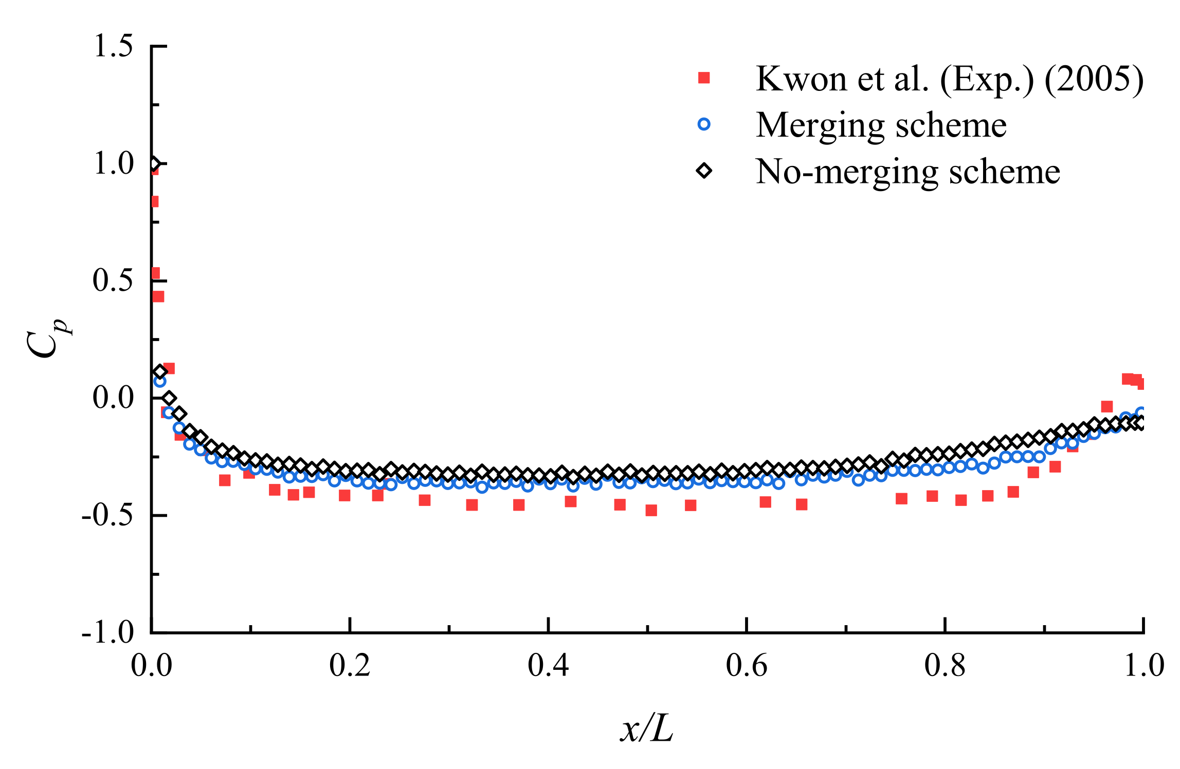
The vortex merging device (see Equation (18)) was introduced by Spalart et al. [23,34] to decrease computing costs by reducing the number of vortex blobs in the wake field. At the same time, this technique may bring about errors in the vorticity distribution, and there has been a lack of discussion in the previous literature about the influence of the vortex merging device on the results. In this paper, a comparison of the time-averaged surface pressure for flow past an elliptic cylinder between the merging and the non-merging algorithm was carried out, as is shown in Figure 4. It turns out that there was little difference between the two algorithms, and that they both showed good agreement with the experimental data. Besides this, the mean drag coefficients of the merging and non-merging scheme were 0.0288 and 0.0278, respectively, when the number of segments was 180. There was not a striking difference between them. Thus, it is feasible to employ this vortex merging scheme to accelerate computing speed.
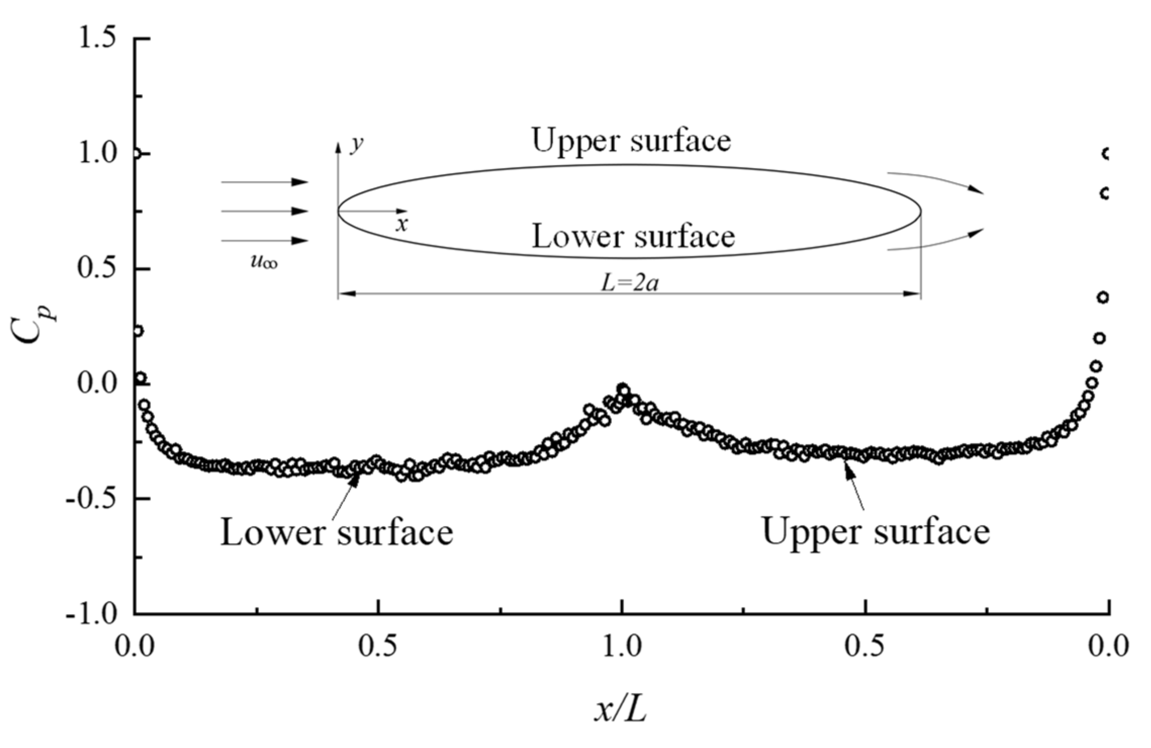
The pressure distributions on the lower and upper surface of the elliptic cylinder mentioned above are shown in Figure 5. It can be observed that the pressure actually returned to its original value when integration around the surface had been completed. Stansby et al. [2] once suggested that it is difficult to make the pressure acting on the last control point consistent with the original value. Encouragingly, the present scheme was able to overcome this deficiency owing to the total circulation of the nascent vortices being equal to zero at each time step rather than the value of the lost circulation.

3.2. Flow Past a Circular Cylinder

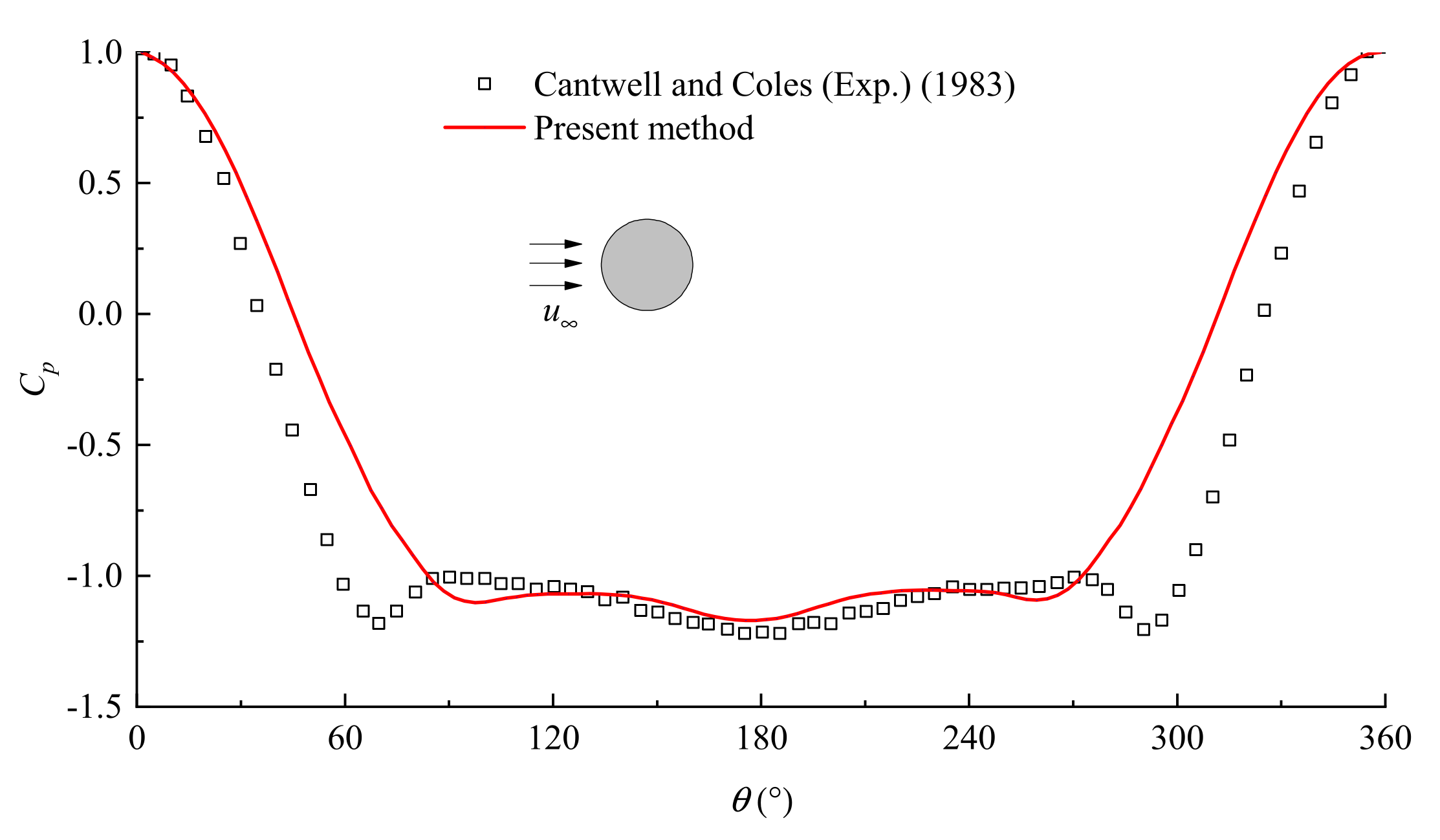
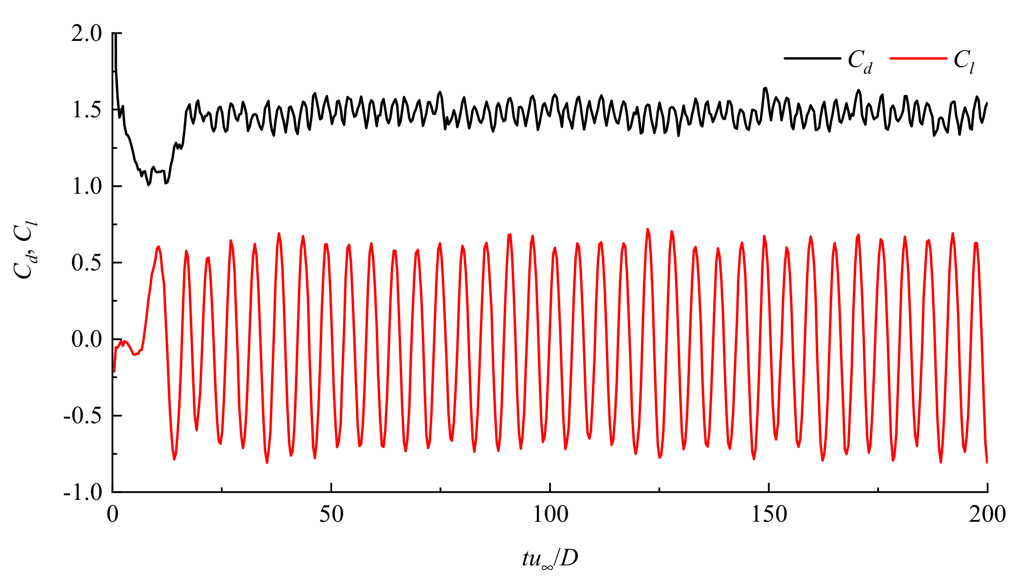
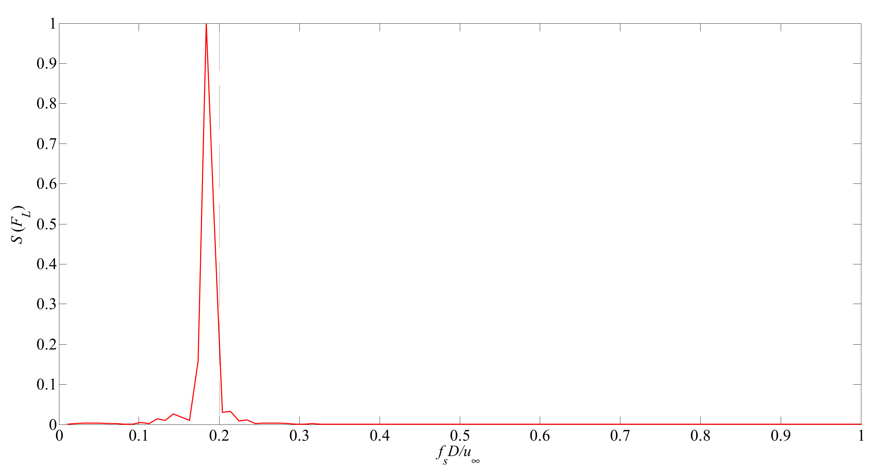
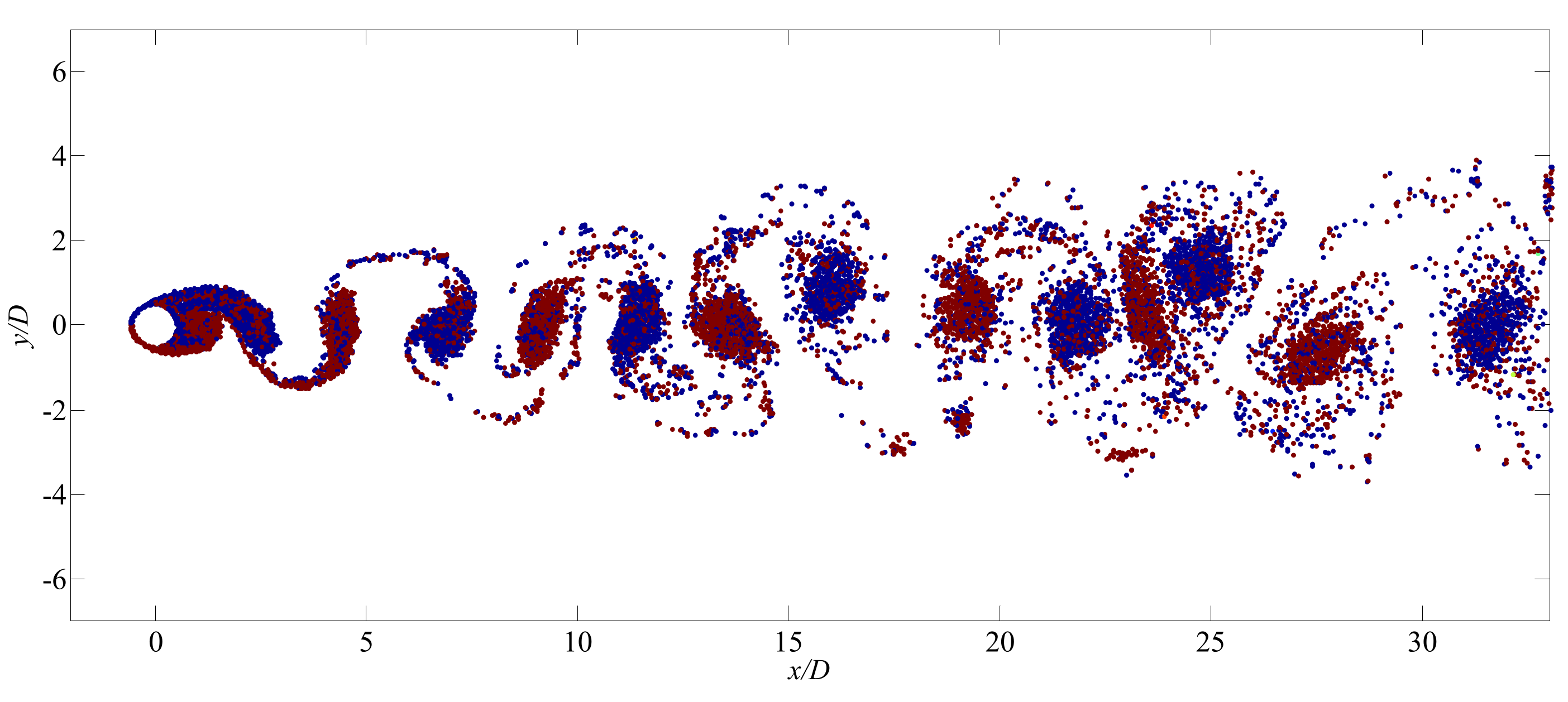
It should be noted that the present simulation can be regarded as an extension of the IVCBC method proposed by Pang et al. [31]. Therefore, we first employ this boundary scheme to calculate the flow past a rigid circular cylinder at R e = 1.4 × 10 5 . The corresponding experimental results were provided by Cantwell and Coles [41]. The mean pressure coefficients calculated by the present vortex method are depicted in Figure 6. Relatively good agreement was obtained between the current results and the available experimental data, while the pressure distribution before the separation point was not predicted well. The time histories of the drag and lift coefficients are shown in Figure 7, where non-dimensional time was employed. It can be observed that the calculated results based on the IVCBC method were smooth. The predicted mean drag coefficient was 1.48 in this case. Based on the fast Fourier transformation (FFT) technique, spectral analysis was carried out to determine the vortex shedding frequency, as shown in Figure 8. The dotted line represents the S t = 0.2 , and the parameter f s denotes the vortex shedding frequency. The vortex shedding for flow past a circular cylinder occurred at S t 0.2 within the subcritical Reynold number region [42,43]. In this case, the calculated Strouhal number ( S t = f s u / D ,where D is the diameter of a circular cylinder) was 0.1837, which is close to 0.2. Furthermore, the vortex pattern in the wake field is depicted in Figure 9, where the red and blue particles represent the positive and negative circulations of the corresponding vortex blobs, respectively. However, we still cannot obtain higher resolution wake fields such as the numerical results calculated by the vortex method provided by Dynnikova [9], especially for the layer boundary region. We can conjecture that the rough representation of the boundary layer brings about unsatisfactory results using the traditional random vortex method.

3.3. Flow Past Elliptic Cylinders with Various Thickness-to-Chord Ratios

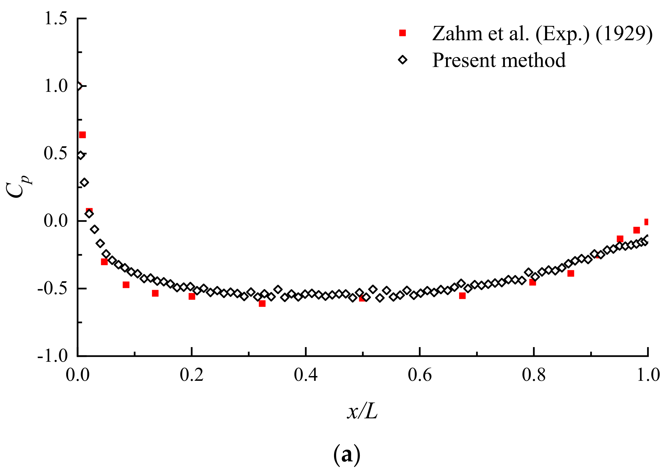
In order to further validate the present method, a series of cases of flow around elliptic cylinders with various thickness-to-chord ratios were carried out. The mean pressure distributions of different cylinders are displayed in Figure 10, including e = 0.25 , e = 0.6 , and e = 0.8 . All of them were in close agreement with the corresponding experimental tests provided by the previous literature [44,45,46,47], where Smith et al. [46] and Carreiro et al. [47] also employed the discrete vortex method to calculate the surface pressure distributions around elliptic cylinders. Figure 11 illustrates the velocity field of all the cases discussed above, where alternate wake vortex structures could be observed. In addition, we provide a table to compare our numerical results for the drag coefficients to other experimental and numerical results available in previous works [40,44,47,48,49,50], as shown in Table 2. This demonstrates that the new scheme performs better than other DVM algorithms in terms of the prediction of fluid forces.

3.4. Flow Past a Joukowski Foil

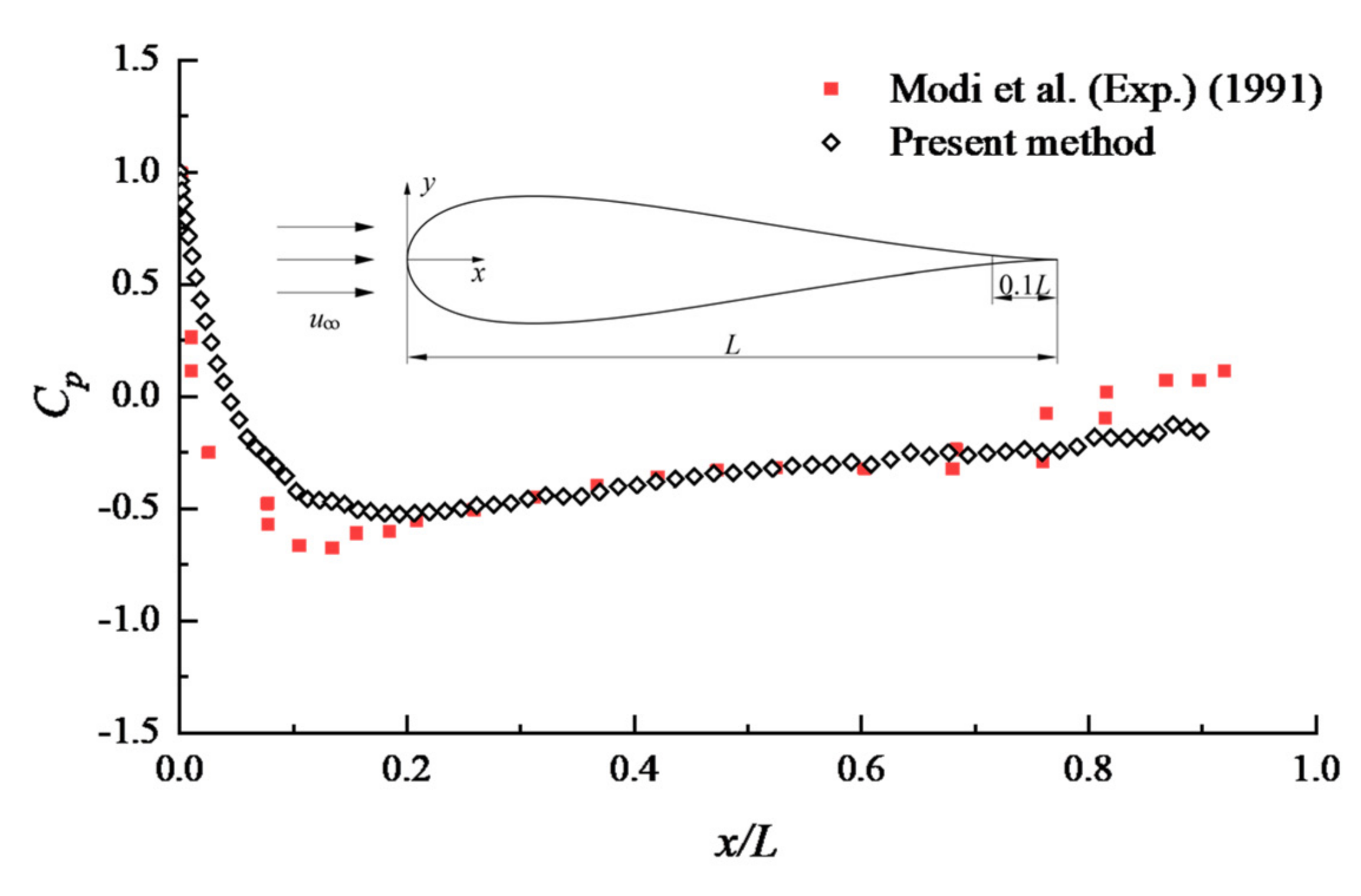
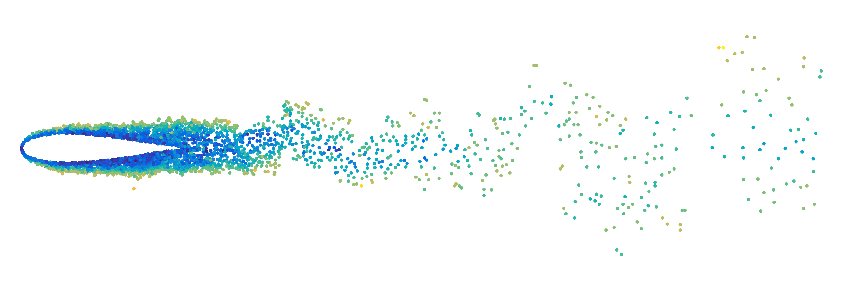
It is well known that the conformal mapping of a Joukowski foil has the same transformation function as an elliptic cylinder; therefore, it is feasible to calculate the flow over a Joukowski foil based on the present scheme. Notice that the only difference is that the circle of the auxiliary plane corresponding to the foil is eccentric. Accordingly, we conduct a simulation of flow past a Joukowski foil with a 0° angle of attack at R e = 4.62 × 10 4 , and the corresponding experimental data was provided by Modi et al. [51]. It should be noted that there existed a sharp corner at the end of the foil, that would eventually lead to an inaccurate solution. Therefore, it is reasonable to just focus on the pressure distribution in the range of up to 0.9-times chord length, ignoring the trailing cusp. A close agreement was still obtained for the time-averaged pressure distribution by using the new vortex scheme, as is shown in Figure 12. However, there were relatively large deviations at the end of the foil, which were similar to the flow past the elliptic cylinder with a thickness-to-chord ratio of 0.16. It can be observed that it is difficult to predict the force performance for a slender body due to the complicated flow characteristics of the afterbody. In addition, the wake field of flow past a Joukowski foil is depicted in Figure 13.

4. Conclusions

In this paper, the conformal mapping method was exploited to address the vortex blob penetration issue for the 2-D discrete vortex method. We first numerically simulated the flow past a circular cylinder based on the IVCBC method. Then, we presented an extension of the IVCBC method to solve flows around arbitrary structures through the conformal mapping technique and the circle theorem. Additionally, systematic simulations were carried out to validate this new algorithm, including flows past elliptic cylinders and a Joukowski foil. It can thus be concluded as follows:
(1)
Instead of traditional boundary treatment in DVM, where any vortex blobs which cross the body surface are removed or reflected back to their mirror image positions, a novel boundary scheme is presented to handle vortices entering into the elliptic cylinder using conformal mapping and the circle theorem. Consider a vortex blob entering the elliptic cylinder; an identical vortex blob is introduced using Joukowski transformation which is located outside the cylinder. Thus, the sum of the circulation of all the vortex blobs is conserved at each time step. In general, the present scheme conducts a redistribution of vortex blobs to keep the structural surface smooth.
(2)
The sensitivity of numerical parameters was discussed, including the time step and the number of segments. It was found that there exists a relationship between them; that is, the determination of the time step needs to consider the number of segments. An equation to estimate the time step size was used that is similar to the CFL criterion in the meshing method. Additionally, it was observed that the influence of vortex merging on the calculation of accuracy can be ignored in DVM.
(3)
The predicted results all show good agreement with the corresponding experimental data for flows over elliptic cylinders with various thickness-to-chord ratios at Reynolds number greater than 1 × 10⁵. Furthermore, the flow past a symmetrical Joukowski foil, without regard to the trailing cusp, was performed, and the mean pressure distributions coincided well with experimental data.
However, it should be noted that the conformal mapping function is not readily available for arbitrary geometry shapes, and thus the present algorithm may become complicated if we tackle flow around various structural cross-sections.

Author Contributions

Methodology, G.J., Z.Z.; software, G.J.; validation, G.J.; investigation, G.J., Z.S. and L.Z.; writing—original draft preparation, G.J. and L.Z.; writing—review and editing, Z.S., Z.Z. and Y.H.; supervision, L.Z.; project administration, L.Z.; funding acquisition, L.Z. All authors have read and agreed to the published version of the manuscript.

Funding

The present work is supported by National Key Research and Development Program of China (2019YFC0312402), (2019YFC0312400). National Natural Science Foundation of China (52071056). The authors would like to thank them for their support.

Institutional Review Board Statement

Not applicable.

Informed Consent Statement

Not applicable.

Data Availability Statement

Not applicable.

Conflicts of Interest

The authors declare no conflict of interest.

References

  1. Chorin, A.J. Numerical Study of Slightly Viscous Flow. J. Fluid Mech. 1973, 57, 785–796. [Google Scholar] [CrossRef]
  2. Stansby, P.K.; Dixon, A.G. Simulation of Flows around Cylinders by a Lagrangian Vortex Scheme. Appl. Ocean Res. 1983, 5, 167–178. [Google Scholar] [CrossRef]
  3. Liao, S. Development and Applications of the Free-Surface Random Vortex Method (FSRVM). Ph.D. Thesis, University of California, Berkeley, CA, USA, 2000. [Google Scholar]
  4. Wu, W. Fluid Mechanics; Beijing University Press: Beijing, China, 1983. [Google Scholar]
  5. Leonard, A. Vortex Methods for Flow Simulation. J. Comput. Phys. 1980, 37, 289–335. [Google Scholar] [CrossRef]
  6. Cheer, A.Y.L. A Study of Incompressible 2-D Vortex Flow Past a Circular Cylinder; University of California: Berkeley, CA, USA, 1979. [Google Scholar]
  7. Dynnikova, G.Y. The Lagrangian Approach to Solving the Time-Dependent Navier-Stokes Equations. Dokl. Phys. 2004, 49, 648–652. [Google Scholar] [CrossRef]
  8. Guvernyuk, S.V.; Dynnikova, G.Y. Modeling the Flow Past an Oscillating Airfoil by the Method of Viscous Vortex Domains. Fluid Dyn. 2007, 42, 1–11. [Google Scholar] [CrossRef]
  9. Dynnikova, G.Y. Calculation of Flow around a Circular Cylinder on the Basis of Two-Dimensional Navier-Stokes Equations at Large Reynolds Numbers with High Resolution in a Boundary Layer. Dokl. Phys. 2008, 53, 544–547. [Google Scholar] [CrossRef]
  10. Dynnikov, Y.A.; Dynnikova, G.Y. Numerical Stability and Numerical Viscosity in Certain Meshless Vortex Methods as Applied to the Navier-Stokes and Heat Equations. Comput. Math. Math. Phys. 2011, 51, 1792–1804. [Google Scholar] [CrossRef]
  11. Giannopoulou, O.; Colagrossi, A.; Di Mascio, A.; Mascia, C. Chorin’s Approaches Revisited: Vortex Particle Method vs Finite Volume Method. Eng. Anal. Bound. Elem. 2019, 106, 371–388. [Google Scholar] [CrossRef]
  12. Rossi, E.; Colagrossi, A.; Bouscasse, B.; Graziani, G. The Diffused Vortex Hydrodynamics Method. Commun. Comput. Phys. 2015, 18, 351–379. [Google Scholar] [CrossRef]
  13. Colagrossi, A.; Rossi, E.; Marrone, S.; Touzé, D.L. Particle Methods for Viscous Flows: Analogies and Differences between the SPH and DVH Methods. Commun. Comput. Phys. 2016, 20, 660–688. [Google Scholar] [CrossRef]
  14. Rossi, E.; Colagrossi, A.; Durante, D.; Graziani, G. Simulating 2D Viscous Flow around Geometries with Vertices through the Diffused Vortex Hydrodynamics Method. Comput. Methods Appl. Mech. Eng. 2016, 302, 147–169. [Google Scholar] [CrossRef]
  15. Rossi, E.; Colagrossi, A.; Graziani, G. Numerical Simulation of 2D-Vorticity Dynamics Using Particle Methods. Comput. Math. Appl. 2015, 69, 1484–1503. [Google Scholar] [CrossRef]
  16. Jin, G.; Zou, L.; Jiang, Y.; Zong, Z.; Sun, Z. A Circle Theorem Technique to Handle 2-D Flows around Arbitrary Cylinders in Discrete Vortex Method. J. Wind Eng. Ind. Aerodyn. 2021, 209, 104496. [Google Scholar] [CrossRef]
  17. Chawdhury, S.; Morgenthal, G. An Extension of Pseudo-3D Vortex Particle Methods for Aeroelastic Interactions of Thin-Walled Structures. J. Wind Eng. Ind. Aerodyn. 2020, 208, 104391. [Google Scholar] [CrossRef]
  18. Chawdhury, S.; Morgenthal, G. Flow Reproduction Using Vortex Particle Methods for Simulating Wake Buffeting Response of Bluff Structures. J. Wind Eng. Ind. Aerodyn. 2016, 151, 122–136. [Google Scholar] [CrossRef]
  19. Lin, K.; Wang, J. Numerical Simulation of Vortex-Induced Vibration of Long Flexible Risers Using a SDVM-FEM Coupled Method. Ocean Eng. 2019, 172, 468–486. [Google Scholar] [CrossRef]
  20. Lin, K.; Wang, J.; Fan, D.; Triantafyllou, M.S. Flow-Induced Cross-Flow Vibrations of Long Flexible Cylinder with an Upstream Wake Interference. Phys. Fluids 2021, 33, 065104. [Google Scholar] [CrossRef]
  21. Pang, J.; Zhu, B.; Zong, Z. A Numerical Simulation Model for the Vortex Induced Vibration of Flexible Risers Using Dynamic Stiffness Matrices. Ocean Eng. 2019, 178, 306–320. [Google Scholar] [CrossRef]
  22. Chorin, A.J. Vortex Models and Boundary Layer Instability. SIAM J. Sci. Stat. Comput. 1980, 1, 1–21. [Google Scholar] [CrossRef] [Green Version]
  23. Spalart, P.R.; Leonard, A.; Baganoff, D. Numerical Simulation of Separated Flows; NASA: Washington, DC, USA, 1983; p. 166. [Google Scholar]
  24. Walther, J.H. Discrete Vortex Method for Two-Dimensional Flow Past Bodies of Arbitrary Shape Undergoing Prescribed Rotary and Translational Motion. Ph.D. Thesis, Technical University of Denmark, Lyngby, Denmark, 1994. [Google Scholar]
  25. Mustto, A.A.; Hirata, M.H.; Bodstein, G. Discrete Vortex Method Simulation of the Flow around a Circular Cylinder with and without Rotation. In Proceedings of the 16th AIAA Applied Aerodynamics Conference, Albuquerque, NM, USA, 15–18 June 1998. [Google Scholar]
  26. Wang, L.; Yeung, R.W. Investigation of Full and Partial Ground Effects on a Flapping Foil Hovering above a Finite-Sized Platform. Phys. Fluids 2016, 28, 071902. [Google Scholar] [CrossRef]
  27. Smith, P.A.; Stansby, P.K. An Efficient Surface Algorithm for Random-Particle Simulation of Vorticity and Heat Transport. J. Comput. Phys. 1989, 81, 349–371. [Google Scholar] [CrossRef]
  28. Smith, P.A.; Stansby, P.K. Viscous Oscillatory Flows around Cylindrical Bodies at Low Keulegan-Carpenter Numbers Using the Vortex Method. J. Fluids Struct. 1991, 5, 339–361. [Google Scholar] [CrossRef]
  29. Chorin, A.J. Vortex Sheet Approximation of Boundary Layers. J. Comput. Phys. 1978, 27, 428–442. [Google Scholar] [CrossRef] [Green Version]
  30. Ghoniem, A.F.; Sherman, F.S. Grid-Free Simulation of Diffusion Using Random Walk Methods. J. Comput. Phys. 1985, 61, 1–37. [Google Scholar] [CrossRef]
  31. Pang, J.H.; Zong, Z.; Zou, L.; Wang, Z. A Novel Vortex Scheme with Instantaneous Vorticity Conserved Boundary Conditions. Eur. J. Mech. BFluids 2016, 59, 219–228. [Google Scholar] [CrossRef]
  32. Pang, J.H.; Zong, Z.; Zou, L.; Wang, Z. Numerical Simulation of the Flow around Two Side-by-Side Circular Cylinders by IVCBC Vortex Method. Ocean Eng. 2016, 119, 86–100. [Google Scholar] [CrossRef]
  33. Wu, J.Z.; Ma, H.Y.; Zhou, M.D. Vorticity and Vortex Dynamics; High Education Press: Beijing, China, 1993. [Google Scholar]
  34. Spalart, P.R.; Leonard, A. Computation of Separated Flows by a Vortex Tracing Algorithm. In Proceedings of the 14th Fluid and Plasma Dynamics Conference, Palo Alto, CA, USA, 23–25 June 1981. [Google Scholar]
  35. Spalart, P.R. Vortex Methods for Separated Flows; NASA: Washington, DC, USA, 1988; p. 66. [Google Scholar]
  36. Degond, P.; Mas-Gallic, S. The Weighted Particle Method for Convection-Diffusion Equations. Part 1: The Case of an Isotropic Viscosity. Math. Comput. 1989, 53, 485–507. [Google Scholar] [CrossRef]
  37. Degond, P.; Mas-Gallic, S. The Weighted Particle Method for Convection-Diffusion Equations Part 2: The Anisotropie Case. Math. Comput. 1989, 53, 509–525. [Google Scholar] [CrossRef]
  38. Ogami, Y.; Akamatsu, T. Viscous Flow Simulation Using the Discrete Vortex Model—the Diffusion Velocity Method. Comput. Fluids 1991, 19, 433–441. [Google Scholar] [CrossRef]
  39. Smith, P.A.; Stansby, P.K. Impulsively Started Flow around a Circular Cylinder by the Vortex Method. J. Fluid Mech. 1988, 194, 45–77. [Google Scholar] [CrossRef]
  40. Kwon, K.; Park, S.O. Aerodynamic Characteristics of an Elliptic Airfoil at Low Reynolds Number. J. Aircr. 2005, 42, 1642–1644. [Google Scholar] [CrossRef]
  41. Cantwell, B.; Coles, D. An Experimental Study of Entrainment and Transport in the Turbulent near Wake of a Circular Cylinder. J. Fluid Mech. 1983, 136, 321. [Google Scholar] [CrossRef] [Green Version]
  42. Blevins, R.D. Flow-Induced Vibration, 2nd ed.; Krieger: Malabar, FL, USA, 2001; ISBN 978-1-57524-183-8. [Google Scholar]
  43. Norberg, C. Flow around a Circular Cylinder: Aspects of Fluctuating Lift Flow. J. Fluids Struct. 2001, 15, 459–469. [Google Scholar] [CrossRef]
  44. Zahm, A.F.; Smith, R.H.; Louden, F.A. Forces on Elliptic Cylinders in Uniform Air Stream; United States Government Printing Office: Washington, DC, USA, 1929. [Google Scholar]
  45. Modi, V.J.; Wiland, E. Unsteady Aerodynamics of Stationary Elliptic Cylinders in Subcritical Flow. AIAA J. 1970, 8, 1814–1821. [Google Scholar] [CrossRef] [Green Version]
  46. Smith, P.A.; Stansby, P.K. Generalized Discrete Vortex Method for Cylinders without Sharp Edges. AIAA J. 1987, 25, 199–200. [Google Scholar] [CrossRef]
  47. Dos Reis Carreiro, F.; Bodstein, G.C.R. Simulação Numérica Do Escoamento Não-Permanente Em Torno de Cilindros Elípticos via Transformação de Joukowsky. In Proceedings of the 9th Brazilian Congress of Thermal Engineering and Sciences, Caxambu, Brazil, 15–18 October 2002. [Google Scholar]
  48. Guedes, V.; Pereira, R.; Magalhaes, C.; Cesar Rachid Bodstein, G. Numerical Simulation of the Two-Dimensional Incompressible Flow around Elliptic Cylinders Using the Vortex Method. In Proceedings of the 17th Brazilian Congress of Thermal Sciences and Engineering, Aguas de Lindoia, Brazil, 25–28 November 2018. [Google Scholar]
  49. Lindsey, W.F. Drag of Cylinders of Simple Shapes; National Advisory Committee for Aeronautics: Washington, DC, USA, 1938; pp. 169–176. [Google Scholar]
  50. Delany, N.K.; Sorensen, N.E. Low-Speed Drag of Cylinders of Various Shapes; National Advisory Committee for Aeronautics: Washington, DC, USA, 1953. [Google Scholar]
  51. Modi, V.J.; Mokhtarian, F.; Fernando, M.S.U.K.; Yokomizo, T. Moving Surface Boundary-Layer Control as Applied to Two-Dimensional Airfoils. J. Aircr. 1991, 28, 104–112. [Google Scholar] [CrossRef]
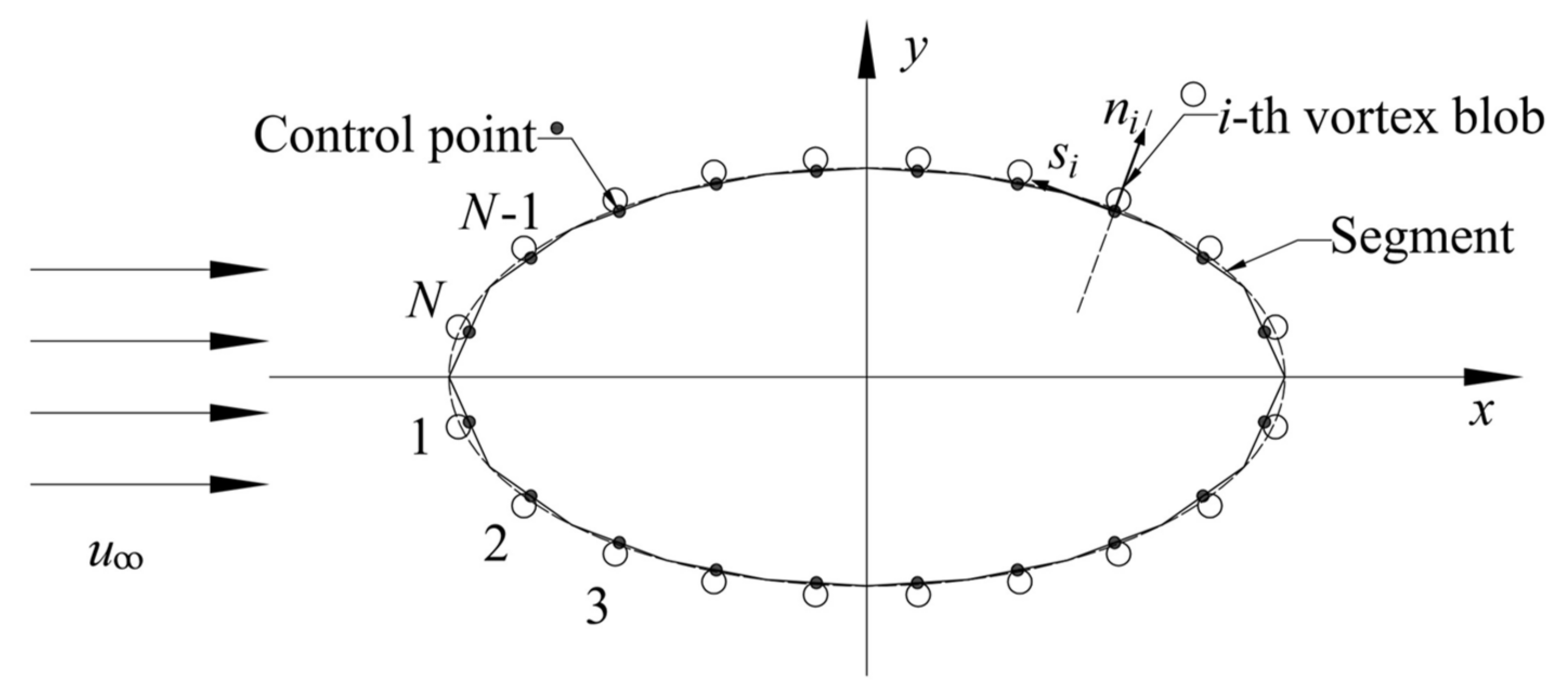
Figure 1. Sketch of body surface discretization and vortex blob generation.
Jmse 09 01409 g001
Figure 2. A novel boundary scheme for dealing with vortex blobs entering an elliptic cylinder based on conformal mapping and the circle theorem: (a) A vortex blob walks across the surface of an elliptical cylinder in the z -plane. (b) A vortex blob entering into the elliptical cylinder is mapped onto the ζ -plane by the inverse function of the Joukowski transformation. (c) The introduced vortex blob outside the circular cylinder in the ζ -plane is obtained by the IVCBC method. (d) The introduced vortex blob, which has the same circulation magnitude and direction outside the elliptic cylinder in the z -plane, can be determined through the Joukowski function.
Jmse 09 01409 g002
Figure 3. Comparison of the mean surface pressure coefficients between various numbers of segments around an elliptic cylinder.
Jmse 09 01409 g003
Figure 4. Comparison of the mean surface pressure coefficient distributions between the merging and non-merging algorithms around an elliptic cylinder.
Jmse 09 01409 g004
Figure 5. Distributions of the mean pressure coefficient on the lower and upper surface of flow past an elliptic cylinder.
Jmse 09 01409 g005
Figure 6. Mean surface pressure coefficients for flow past a circular cylinder.
Jmse 09 01409 g006
Figure 7. Time histories of drag and lift coefficients.
Jmse 09 01409 g007
Figure 8. Spectral analysis of vortex shedding.
Jmse 09 01409 g008
Figure 9. Vortex pattern in the wake field.
Jmse 09 01409 g009
Figure 10. Mean surface pressure coefficients for flow past elliptic cylinders with various thickness-to-chord ratios. (a) e = 0.25 , R e = 2 × 10 5 ; (b) e = 0.6 , R e = 1 × 10 5 ; (c) e = 0.8 , R e = 1 × 10 5 .
Jmse 09 01409 g010aJmse 09 01409 g010b
Figure 11. Velocity fields for flow past elliptic cylinders with various thickness-to-chord ratios. (a) e = 0.25 , R e = 2 × 10 5 ; (b) e = 0.6 , R e = 1 × 10 5 ; (c) e = 0.8 , R e = 1 × 10 5 .
Jmse 09 01409 g011aJmse 09 01409 g011b
Figure 12. Distribution of the mean surface pressure around a Joukowski foil.
Jmse 09 01409 g012
Figure 13. Velocity field for flow past a Joukowski foil at R e = 4.62 × 10 4 .
Jmse 09 01409 g013
Table 1. Comparison of the mean drag coefficient with experimental data.
Case N Δ t R e C ¯ D
Kwon et al., (2005) (Exp.) [40]--3 × 1050.021
Case 11200.153 × 1050.035
Case 21800.13 × 1050.0288
Case 32400.0753 × 1050.0258
Table 2. Comparison of the mean drag coefficient with other numerical and experimental results.
Case e R e C ¯ D
Kwon et al., (2005) (Exp.) [40]0.163 × 1050.021
Present method0.163 × 1050.0258
Lindsey (Exp.) (1938) [49]0.252 × 1050.0576
Zahm et al., (Exp.) (1929) [44]0.252 × 1050.0466
Present method0.252 × 1050.0495
Lindsey (Exp.) (1938) [49]0.251 × 1050.08
Carreiro et al., (DVM) (2002) [47]0.251 × 1040.21
Guedes et al., (DVM) (2018) [48]0.251 × 1050.12
Present method0.251 × 1050.0654
Delany et al., (Exp.) (1953) [50]0.51 × 1050.30
Carreiro et al., (DVM) (2002) [47]0.51 × 1040.49
Guedes et al., (DVM) (2018) [48]0.51 × 1050.35
Present method0.51 × 1050.256
Publisher’s Note: MDPI stays neutral with regard to jurisdictional claims in published maps and institutional affiliations.