Abstract
Knowledge from historical earthquake events indicates that a submarine tunnel crossing active strike-slip faults is prone to be damaged in an earthquake. Previous studies have demonstrated that the flexible joints are an effective measure for a submarine tunnel crossing a strike-slip fault. The background project of this paper is the second submarine tunnel of Jiaozhou bay. In this work, model tests and numerical simulations are conducted to investigate the deformation and failure mechanism of a submarine tunnel with flexible joints under a strike-slip fault dislocation. The influence of strike-slip faults on a tunnel with flexible joints has been investigated by examining the deformation of rock mass surface, analyzing lining stains, and crack propagation from model tests. Numerical simulations are conducted to study the effects of the design parameters of a tunnel with flexible joints on the mechanical response of the lining. The results showed that the ‘articulated design’ measure can improve the ability of the tunnel to resist the strike-slip faults. In terms of the mechanism of design parameters of a tunnel with flexible joints, this paper finds that increasing the lining thickness, decreasing the lining segment length, and decreasing the tunnel diameter to a reasonable extent could effectively improve the performance of this faulting resistance measure for a tunnel under the strike-slip fault zone dislocation. Compared with the horseshoe tunnel cross-section, the circular tunnel cross-section can improve the ability of the faulting resistance of a tunnel with flexible joints, while the optimal angle of the tunnel crossing the fault zone is 90º. It is concluded that the wider fault zone, smaller flexible joint width, and less stiffness of the flexible joint could make lining safer under a strike-slip fault dislocation. The above research results can serve as a necessary theoretical reference and technical support for the design of reinforcement measures for a submarine tunnel with flexible joints under strike-slip fault dislocation.
1. Introduction
Tunnels in high seismic risk regions inevitably cross active faults and thus are threatened by their movement. Historical records from past earthquake events show that due to poor geological conditions or abrupt geological changes, a tunnel near active fault zones would suffer severe damage. For example, in the 1999 Mw 7.6 Chi-chi earthquake, Wang et al. [1] found that tunnels suffered some degree of damage in sections crossing active faults. In the 1906 Mw 8.3 San Francisco earthquake, the Wright railroad tunnel crossing the San Andreas fault suffered severe damage, with a maximum fault dislocation of 1.5 m [2]. The Sichuan-Tibet railway crosses more than 10 deep and large active fault zones. The dislocation of those faults would cause adverse influences on the railway [3].
By the movement mode, faults can be divided into three types: normal, reverse, and strike-slip faults. Abundant literature exists for the dislocation problem of normal and reverse faults [4,5,6,7,8,9,10]. However, strike-slip faults account for a considerable proportion of active faults in areas such as Japan and southeastern China. Therefore, it is of great practical significance to study the deformation and failure mechanism of a submarine tunnel with flexible joints subjected to strike-slip fault dislocation. In the design work for a submarine tunnel crossing active faults, it is important to adopt proper tunnel cross-section type and specific reinforcement measures.
Many scholars have studied the issue of tunnels crossing active strike-slip faults with numerical simulations and model tests [11,12,13,14,15,16]. For numerical simulation studies, Jalali [17] describes a novel approach for seismic reinforcement of segmental tunnels located in active fault zones, which is termed the sequential joints method. In this method, a flexible joint is located between each segment to avoid the overall failure of the tunnel structure. Zhong et al. [18] proposed two quantitative damage indices, namely the overall structural damage index and the concrete lining crack width, to study the structural integrity and availability of the water conveyance tunnel under fault movements. An et al. [19] proposed a two-level design method to be applied to shallow urban tunnels under fault dislocation. The results show that the two-level design content during fault dislocation is consistent with that of seismic design. Meanwhile, for experimental model test studies, Liu et al. [20] studied the effects of fault dip angle on the internal force, deformation, and damage characteristics of tunnel structures crossing faults by model tests. Kiani et al. [21] carried out a study on the effect of fault dip angle and the thickness of the overburden layer of the tunnel on the damage characteristics and the damage range of a shallow shield tunnel under a normal fault dislocation. Sabagh et al. [22] investigated the effect of a normal fault of dislocation of 60° dip angle on the tunnel through with the ng-model test. The damage location and damage mechanism of the model tunnel were evaluated. Yao et al. [23] investigated the active length of stainless-steel pipes and concrete tunnels under the action of reverse faults by centrifugal and numerical simulations.
According to the experience of tunnel projects through active faults, the faulting resistance measure of a tunnel with flexible joints crossing faults is divided into two categories, i.e., ‘over-excavation design’ and ‘articulated design’ [24,25,26,27,28]. Historical records of tunnel projects crossing faults indicate that ‘articulated design’ is a common faulting resistance measure. Specifically, this measure refers to a flexible joint with low stiffness compared to the lining that is adopted between lining segments. Cui et al. [29] studied the effect of faulting resistance measures of a tunnel under a normal fault dislocation with model tests. Shahidi and Vafaeian [30] adopted plastic concrete to reduce the stiffness of flexible joints between lining sections in the Koohrang-III water conveyance tunnel crossing the Zarab active fault. Zhao et al. [31] proposed a new type of plastic concrete, which was adopted in the Xianglushan tunnel. Furthermore, the effectiveness of this concrete was verified by laboratory tests and numerical simulations, and the mechanical properties of this new fiber-plastic concrete were determined. Yan et al. [32] investigated the response and damage pattern of a tunnel with flexible joints under the normal fault dislocation by numerical simulations and model tests. Wen et al. [33] presented the tunnel structure influence range and lining segment setting method through numerical simulation and model testing.
The above research results may provide some design reference for a submarine tunnel crossing strike-slip fault. Although many tunnel projects have taken certain measures to resist the strike-slip fault, a systematic study has not been conducted for faulting resistance measures and calculation methods on this issue. Especially in the physical model test, insufficient effort has been put into the study of the damage mechanism of a submarine tunnel with flexible joints under strike-slip fault dislocation. Furthermore, in terms of the mechanism of the design parameters for a tunnel with flexible joints to resist faulting, the effect of these design parameters requires further investigation. In addition, it is difficult for some design parameters to be studied by model tests due to the complex environment.
In this work, model tests and numerical simulations are conducted to investigate the deformation and failure mechanism of a submarine tunnel with flexible joints under the strike-slip fault dislocation. The influence of strike-slip faults on a tunnel with flexible joints has been investigated by examining the deformation of a rock mass surface, analyzing lining stains, and crack propagation from model tests. Meanwhile, the effects of parameters of ‘articulated design’ are investigated, such as lining segment length, lining thickness, tunnel diameter, the angle between tunnel and fault zone, and tunnel cross-section type. Based on the results of the model tests, the verification of numerical models is performed to ensure that they can produce reasonable predictions. Numerical simulations are conducted to study the effects of the design parameters of a tunnel with flexible joints on the mechanical response of linings, such as fault width, flexible joint width, and flexible joint stiffness.
2. Model Tests
The model test is considered to be a credible method to study the response mechanism of lining structures and also the basis of numerical simulation and theoretical analysis. In this paper, multiple small-scaled model tests are used to research the failure mechanism and effects of design parameters for submarine tunnels with flexible joints under strike-slip fault dislocation. The verification of numerical models is performed to ensure that they can produce reasonable predictions.
2.1. Experimental Apparatus
The test is conducted with a self-developed experimental apparatus, as shown in Figure 1. The model box is divided into the active side and fixed side. The active side achieves horizontal movements with a hydraulic jack. The maximum horizontal move distance of the shear box is 10 cm, and the horizontal move velocity is 0.125 mm/s. As shown in Figure 1b, the dimensions of the box are 72 × 50 × 40 cm (L × W × H). The length of the active side (LH) is 42 cm, and the length of the fixed side (LF) is 30 cm. The model box could not realize the width of the fault model calculated by the similarity ratio and the prototype width of the fault. Meanwhile, this paper mainly researches the effects of ‘articulated design’ parameters on the ability of a submarine tunnel with flexible joints to resist strike-slip faults. Thus, the width of the fault zone in model (Wf) tests is set to 10 cm.
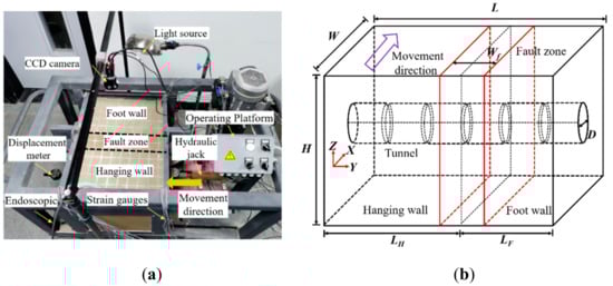
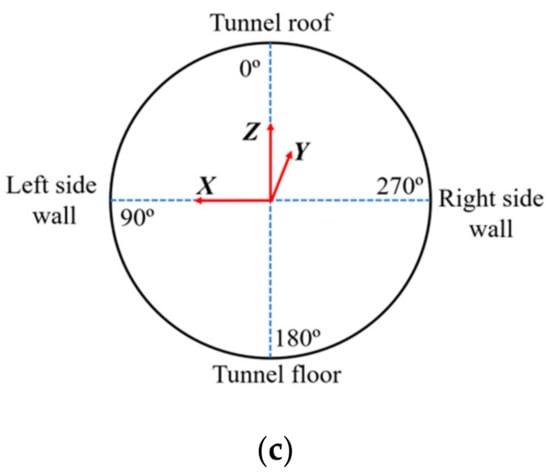
Figure 1.
Equipment for experiment (a) apparatus; (b) model dimension; (c) cross-section of lining.
2.2. Model Preparation
This paper intends to carry out a comprehensive study on a submarine tunnel with flexible joints to resist strike-slip fault dislocation. As the large-scale model test is costly and difficult to perform, a smaller similarity ratio is adopted in this work; this means that the physical model test takes a geometric similarity ratio of = 100. It is difficult to consider the gravity effect using the artificial mass method due to the small size of the tunnel model. Therefore, the density similarity ratio is = 2.4. Based on the similarity principle, the similarity ratios of physical and mechanical parameters are listed in Table 1.

Table 1.
Physical Parameters and Similarity Ratio.
Through model material proportioning tests, the quality ratio of the rock mass model in the hanging wall and footwall was adopted for 1:0.6:0.1:0.1 (river sand:barite powder:water glass:water), and the fault zone model adopted river sand. Furthermore, gypsum, water, barite powder, and diatomite were used to simulate the lining model with a quality ratio of 1:1.2:0.6:0.25. Table 2 shows the mechanical parameters of the model.
Table 2.
Mechanical Parameters of the Model.
The design of the flexible joints of a tunnel is the most difficult issue of the model tests. In this work, the steel wire and flexible rubber are conducted to make flexible joints. This design can efficiently simulate the movement of the flexible joint during strike-slip fault dislocation. Specifically, the width of the flexible joint is 2 cm, and the width of the flexible rubber is 5 cm. The flexible joint model is illustrated in Figure 2. The lining is equipped with a single layer of steel wire mesh, and the lining reinforcement rate is calculated following the simplified equal strength principle [34]. Finally, ∅ 0.6 mm steel wires were used for the lining, and the distance between the two wires is 8 mm.
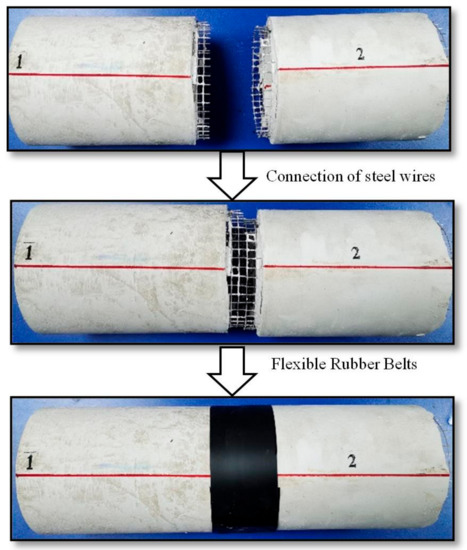
Figure 2.
Flexible joints model.
2.3. Measuring Instruments
The experimental measurement instruments are shown in Figure 3, which includes: (a) CCD camera to record the deformation of rock mass surface and the crack propagation of a shear zone; (b) Endoscope to record the deformation and damage characteristics of the inside surfaces of the tunnel; (c) Strain gauges to record the strain evolution in the lining.
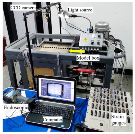
Figure 3.
Measuring instruments of model test.
According to the results of the numerical simulation, the tunnel model size and the experimental conditions, the strain monitoring sections, and measurement points on the lining are reasonably arranged. Details of strain gauges on a tunnel with flexible joints are shown in Figure 4. The LZ, RZ, TZ, and FZ indicate the longitudinal strains in the left wall, right wall, roof, and floor of a tunnel, while the LH, RH, TH, and FH indicate the circumferential strains in the left wall, right wall, roof, and floor of a tunnel.
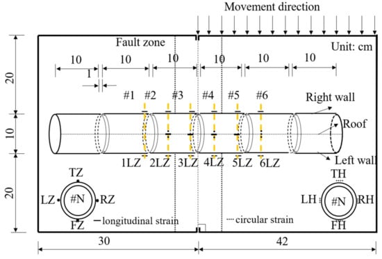
Figure 4.
Strain gauges arrangement in a tunnel with flexible joints.
3. Model Test Results
3.1. Comparison between a Lining with Joints and a Lining without Joints
To study the deformation and damage mechanisms of a submarine tunnel with flexible joints under the strike-slip fault dislocation, several comparisons of experimental results between lining with joints and lining without joints are obtained from the observations of deformation of rock mass surface, analyzing tunnel stain and crack propagation in this study. The cases of tunnel models are shown in Table 3, where the length of the lining without joints is 60 cm. Both linings with joints and linings without joints models are shown in Figure 5.
Table 3.
Cases of Model Tests.
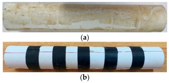
Figure 5.
Tunnel models. (a) lining without joints; (b) lining with joints.
3.1.1. Deformation of Rock Mass Surface
The deformation pattern of the rock mass surface in case 0 is given in Figure 6a. First, the surface of the rock mass appeared a shear crack at the fault zone. As the fault displacement reached 30 mm, several cracks of the surface appeared at the boundary between the fault zone and the two plates. The cracks of the rock mass surface are basically distributed in the fault zone under the dislocation of a strike-slip fault. Meanwhile, Figure 6b gives the deformation pattern of the rock mass surface in case 1. When the fault displacement is 20 mm, two shear cracks are generated on the rock mass surface in the fault zone. This vertical crack through the fault zone as the fault moves is 50 mm, while six oblique cracks appear on the fault zone.
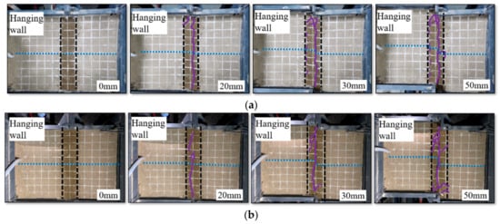
Figure 6.
Deformation of rock mass for tunnel models. (a) lining without joints; (b) lining with joints.
3.1.2. Damage Pattern of the Tunnel Structure
As shown in Figure 7 and Figure 8, there are many differences in lining deformation and damage pattern between lining without joints and lining with joints. It should be noted that Figure 7a shows the status of a tunnel without flexible joints at 50 mm fault zone displacement, and Figure 7b shows the status of a tunnel with flexible joints at 80 mm fault zone displacement. For a tunnel without flexible joints, the tunnel structure is seriously damaged when subjected to strike-slip fault dislocation. The deformation in the lining is mainly focused on the fault zone. Multiple longitudinal and circular cracks are observed on the lining. The tunnel circular cross-section became an oval shape due to the extrusion of the rock mass. Additionally, the tunnel’s tendency to collapse was obvious through the observation of the endoscope. On the other hand, for a tunnel with flexible joints, the lining damage pattern was mainly exhibited with the failure of the flexible joints in the fault zone. Under the compression-shear effect of the fault zone, notable rotation occurs between the lining segments. There are no obvious cracks found on this tunnel lining structure. Meanwhile, the deformation of the tunnel is S-shaped after a strike-slip fault dislocation. The flexible rubber belt was detached between lining segments #2 and #3.
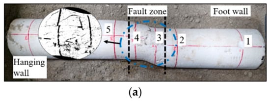
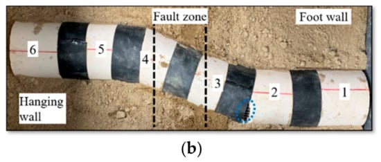
Figure 7.
Damage pattern of the tunnel. (a) lining without joints; (b) lining with joints.
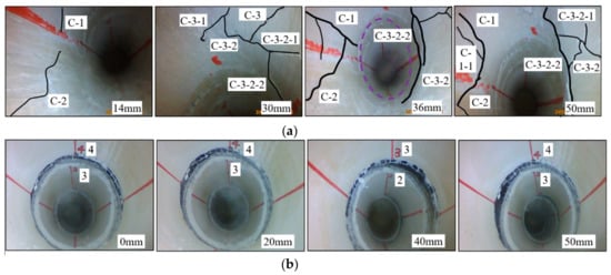
Figure 8.
Deformation and cracking of the tunnel after fault dislocation. (a) lining without joints; (b) lining with joints.
The lining cracks distribution of both cases 0 and 1 were plotted in Figure 9. For a tunnel without flexible joints in case 0, the cracks of the lining are mainly focused on cross-sections #2 and #3. These cracks include longitudinal cracks, circular cracks, and oblique cracks. The damage pattern in lining without joints is the combination of shear and bending damage, and the lining damage is concentrated in the fault zone. The tunnel damage range is 4 Wf in case 0. For a tunnel with flexible joints in case 1, the lining cracks mainly appear on the lining segment #3. Therefore, lining segment #3 in the fault zone suffers serious damage. The tunnel damage range is 2.1 Wf in case 1, and the damage range in lining with flexible joints is reduced by 48% compared to the damage range in the lining without joints.
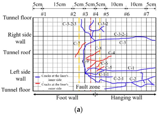
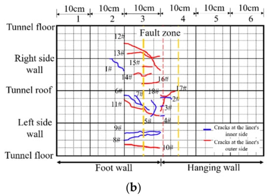
Figure 9.
Distribution of cracks. (a) lining without joints; (b) lining with joints.
3.1.3. Longitudinal Strains
The variation of longitudinal strains in the lining of both cases 0 and 1 are shown in Figure 10, where positive values are tensile strains, and negative values are compressive strains.
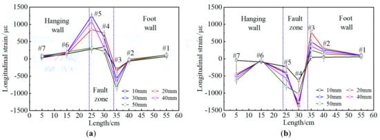
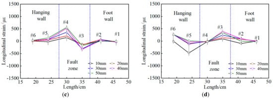
Figure 10.
Longitudinal strain of a tunnel under different fault displacements. (a) lining without joints, left wall; (b) lining without joints, right wall; (c) lining with joints, left wall; (d) lining with joints, right wall.
The longitudinal strains of the side wall in cross-sections #1, #2, and #6 of tunnels without joints keep the constant state with the increase of a strike-slip fault movement. Moreover, the maximum longitudinal tensile strain of the side wall is 1244 με in cross-section #5, and the maximum compressive strain of the side wall is −1427 με in cross-section #4. For a tunnel with flexible joints in case 1, the longitudinal strains of the side wall gradually increase in cross-sections #3 and #4, but lining structures would not reach the yield state. Meanwhile, the maximum longitudinal tensile strain of the side wall is 544 με in cross-section #4, and the maximum compressive strain of the side wall is −474 με in cross-section #5. Both cross-sections are located in the fault zone. It can be found that the lining strain of the tunnel far from the fault zone is small and hardly affected by the strike-slip fault dislocation. Conversely, the lining strains near the fault zone are large and prone to failure. Compared with the tunnel without flexible joints, the maximum longitudinal tensile strain in the side walls of a tunnel with flexible joints is reduced by 56%, and the maximum longitudinal compressive strain is reduced by 68%. This suggests that the ‘articulated design’ measure can improve the ability of the tunnel to resist the strike-slip faults.
3.2. Analysis for Design Parameters of a Tunnel with Flexible Joints
The previous model tests verified that the ‘articulated design’ measure is an effective measure for submarine tunnels crossing strike-slip faults to resist fault rupture. However, the mechanism of design parameters of a tunnel with flexible joints is still in need of further investigation on the deformation and damage mechanism under strike-slip fault movements, such as lining segment length and lining thickness, tunnel diameter, and so on. Therefore, a series of small-scale model experiments were performed to analyze the effects of design parameters of ‘articulated design’, such as lining segment length, lining thickness, tunnel diameter, the angle between tunnel and fault zone, and tunnel cross-section type. These cases of a tunnel with flexible joints model are shown in Table 4.
Table 4.
Cases of Model Tests for ‘Articulated Design’.
3.2.1. Distribution of Longitudinal Strains in the Tunnel
Figure 11 illustrates the longitudinal strain curves of the side walls of a tunnel with flexible joints of each case. The maximum longitudinal strains in the lining of each case subjected to the strike-slip fault movement are shown in Table 5. It is known that concrete easily fails under tension, so this paper focuses on the analysis of the maximum tensile strain in the lining’s side walls. Compared with case 1, the increment of the maximum tensile strain of the lining in case 2 is 152%, which is the highest of all cases; the increment of the maximum tensile strain of the lining in case 6 is 4.8%, which is the least of all cases.
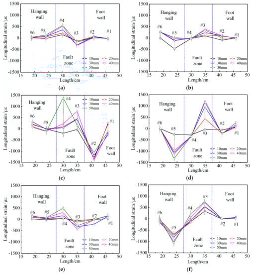
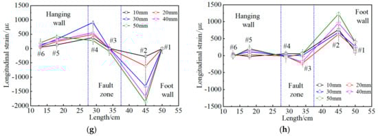
Figure 11.
The longitudinal strain of a tunnel with flexible joints under different fault displacements. (a) Case 1, left wall; (b) Case 1, right wall; (c) Case 2, left wall; (d) Case 2, right wall; (e) Case 3, left wall; (f) Case 3, right wall; (g) Case 4, left wall; (h) Case 4, right wall.
Table 5.
The Maximum Longitudinal Strain of Lining.
Figure 12 shows the strain response of the lining side walls under fault misalignment. Under the effect of the strike-slip fault movement, the longitudinal strains in lining far away from the fault zones are very small. Thus, the lining far away from the fault zones is hardly affected by the strike-slip fault. On the contrary, the longitudinal strains in lining near fault zones is larger, so it could be prone to yield failure. From the strain response of the lining structure, large deformation occurs in the lining of the hanging wall due to the extrusion of the rock mass caused by horizontal movements of the active side. Meanwhile, the left wall in lining is in a tensile state, and the right wall’s lining presents a compressed state around the fault zones. Lining in the foot wall is basically stationary. In the foot wall, the left wall’s lining is in a compressed state, and the right wall’s lining is in a tensile state at the boundary of the two plates and the fault zone.
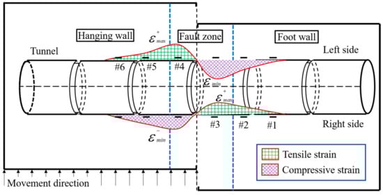
Figure 12.
Schematic diagram of strain response of the lining under strike-slip fault dislocation.
3.2.2. Deformation and Damage Pattern of the Tunnel Structure
The deformation and failure of a tunnel with flexible joints subjected to the strike-slip fault zone for each case are shown in Figure 13 and Figure 14.
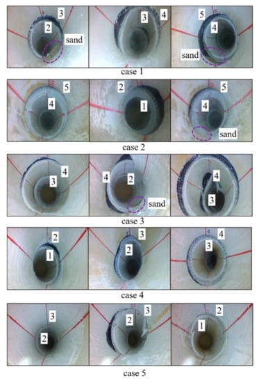
Figure 13.
Damage pattern of the lining segments of each case.
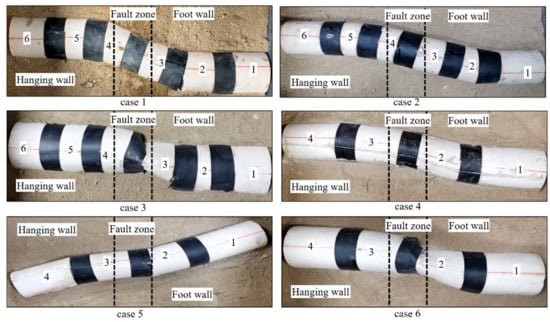
Figure 14.
Deformation of lining structure of each case.
The lining damage pattern for each case is the failure of flexible joints in the fault zone, rotation between the lining segments, and S-shaped lining deformation. However, the flexible rubber bands between segments 2 and 3 and between segments 4 and 5 were disconnected in case 1, resulting in sand materials collapsing into the tunnel. The tunnel cross-section in case 2 has no obvious deformation, and it has the lowest damage level among all cases. The lining with flexible joints of case 3 has large rotation and movements, and it has the most severe damage level among all cases. It can be concluded that a thicker lining could reduce the degree and range of the damage in lining structure. Meanwhile, the lining segments 3 and 4 have large elliptical deformation.
In terms of the mechanism of design parameters of a tunnel with flexible joints, this paper finds that increasing the lining thickness, decreasing the lining segment length, and decreasing the tunnel diameter to a reasonable extent could effectively improve the performance of this faulting resistance measure for a tunnel under strike-slip fault zone dislocation. Compared with the horseshoe tunnel cross-section, the circular tunnel cross-section can improve the ability of the faulting resistance of a tunnel with flexible joints, while the optimal angle of the tunnel crossing the fault zone is 90°.
4. Verification
Many design parameters of a tunnel with flexible joints cannot be analyzed by model tests in this work. Therefore, it is necessary to analyze the mechanism of design parameters of a tunnel with flexible joints through numerical simulation, such as fault zone width, flexible joint width, and flexible joint stiffness. Verification of numerical models is performed to ensure that numerical simulations can produce reasonable predictions. In addition, large-scale numerical models utilize the calibrated numerical modeling approach to make the numerical simulation results more credible.
Based on the physical model test of case 1, a small-scale numerical calculation model is established, as shown in Figure 15. The material of rock mass adopts the M-C model, and the material of both lining and flexible joints adopts the elastic model. The width of the flexible joint is 1 cm, and the length of the lining segment is 10 cm in this numerical model.
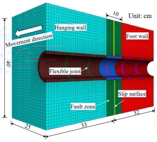
Figure 15.
Rock mass-tunnel model.
Figure 16 and Figure 17 show the comparison of numerical results and model experiment results under 50 mm of fault movement. The value of the longitudinal strain in each lining segment of the model test and the numerical simulation shows some deviations due to the accuracy of measuring instruments in model tests and the elastic behavior model of the lining in the numerical simulation and so on. However, it is basically comparable for longitudinal strain distribution of lining on the numerical simulation and model tests, and the maximum strain of the lining of both numerical simulation and model test is concentrated in the fault zone. Meanwhile, the lining deformation and damage pattern in the numerical simulation is consistent with the results of the model test. Thus, the small-scale numerical simulation is consistent with the results of the model test, and this numerical model can provide a model basis for the calculation of large-scale tunnel projects in this paper.
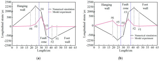
Figure 16.
Longitudinally strained side walls of the tunnel in the numerical and model experiments. (a) left wall; (b) right wall.
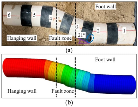
Figure 17.
Failure pattern of the tunnel for numerical and model experiments. (a) model experiment; (b) numerical simulation.
5. Numerical Model Test
5.1. Numerical Model
Numerical simulations are conducted by Flac3D to study the effects of design parameters of a submarine tunnel with flexible joints on the internal force and moment response of linings, such as fault width, flexible joint width, and flexible joint stiffness. The stiffness of the flexible joint material is determined by the ratio of Young’s modulus of flexible joints to Young’s modulus of the lining [35]. The background project of this paper is the second submarine tunnel of Jiaozhou bay.
The model was established as shown in Figure 18; Table 6 shows the mechanical parameters of the numerical model. A very refined mesh was performed to ensure the accuracy of the numerical simulation on critical parts of the numerical model [36,37,38,39], such as the lining and the boundary of the rock mass and fault zones. The interface between the tunnel and the rock mass was called the ‘T-R interface ‘. All boundaries of the foot wall and the upper, lower boundaries of the hanging wall are fixed. To simulate the strike-slip fault dislocation, displacement along the fault movement direction is applied at the front and rear boundaries of the hanging wall. The calculation scheme is shown in Table 7. The longitudinal internal force and moment response in the lining with flexible joints includes the equivalent axial force, moment, and shear, due to the tunnel lining being considered as an elastic beam.
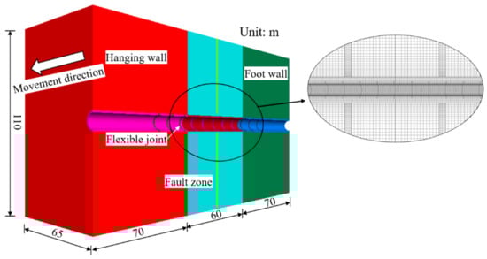
Figure 18.
Calculation model.
Table 6.
Mechanical Parameters of the Numerical Model.
Table 7.
Calculation Schemes.
5.2. Effects of Fault Width
The longitudinal internal force and moment distribution curve of a tunnel with flexible joints under the influence of different fault widths are shown in Figure 19. When the fault width increases from 40 to 80 m, the maximum liner equivalent axial force decreases from 10.68 to 4.80 MN, with a decrease of 55.1%, and the maximum liner moment decreases from 276.52 to 114.90 MN·m, with a decrease of 58.4%, while the maximum liner shear decreases from 42.56 to 24.83 MN, with a decrease of 41.6%. Furthermore, the average decrease of linear internal force and moment is 51.7%. In summary, the influence of the fault width is mainly expressed in the internal force and moment response; specifically, if the fault zone became wider, the internal force and moment of lining would be distributed in a larger area under the same strike-slip fault zone displacement; thus, the internal force and moment will be reduced, and the lining structure will be safer.
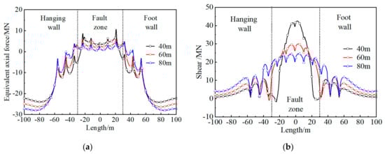
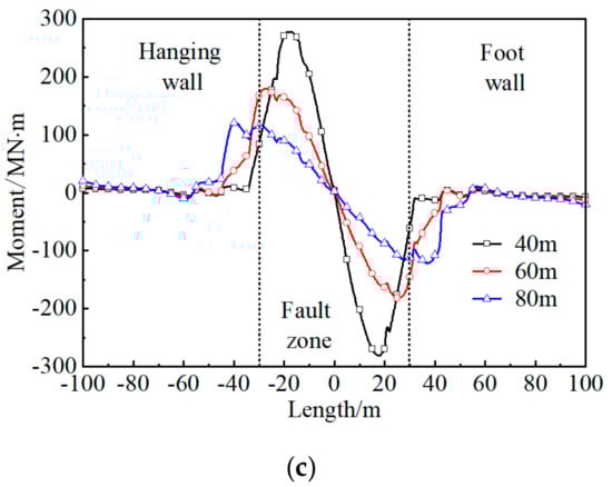
Figure 19.
Distribution of internal force and moment for a tunnel under different fault widths. (a) equivalent axial force; (b) shear; (c) moment.
5.3. Effects of Flexible Joint Width
The longitudinal internal force and moment distribution curve of a tunnel with flexible joints under the influence of different flexible joint widths are shown in Figure 20. When the flexible joint width increases from 0.25 to 1 m, the maximum liner equivalent axial force increases from 3.41 to 6.16 MN, with an increase of 80.6%, and the maximum liner moment increases from 108.80 to 178.64 MN·m, with an increase of 64.2%, while the maximum liner shear increases from 11.22 to 29.54 MN, with an increase of 163%. Furthermore, the average increase of liner internal force and moment is 101.2%. In summary, it is beneficial to adopt a smaller flexible joint width to improve the ability of a tunnel with flexible joints to resist strike-slip fault dislocation.
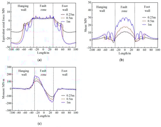
Figure 20.
Distribution of internal force and moment for a tunnel under different joint widths. (a) equivalent axial force; (b) shear; (c) moment.
5.4. Effects of Flexible Joint Stiffness
The longitudinal internal force and moment distribution curve of a tunnel with flexible joints under the influence of different flexible joint stiffness is shown in Figure 21. When the flexible joint stiffness increases from 1/200 to 1/50, the maximum liner equivalent axial force increases from 4.2 to 9.43 MN, with an increase of 124%, and the maximum liner moment increases from 110.51 to 291.78 MN·m, with an increase of 164%, while the maximum liner shear increases from 25.47 to 36.87 MN, with an increase of 44.5%. Furthermore, the average increase of liner internal force and moment is 110.8%. It is useful for the flexible joints to use less stiffness to improve the capability of a tunnel to resist strike-slip fault zones dislocation.
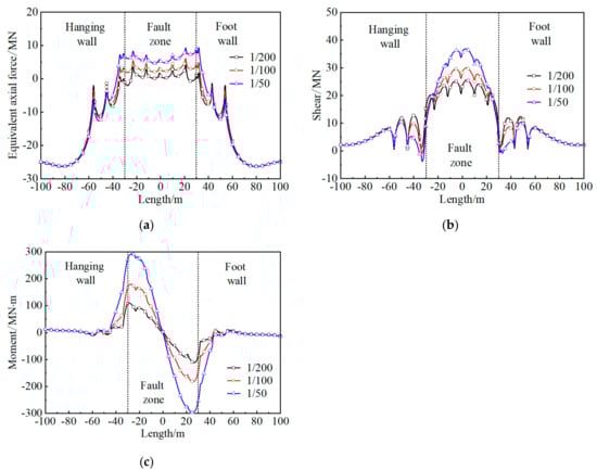
Figure 21.
Distribution of internal force and moment for a tunnel under different flexible joint stiffness. (a) equivalent axial force; (b) shear; (c) moment.
The numerical simulation results show that the lining internal force and moment in the fault zone appears to be sawtooth variation, while there is an obvious drop at the flexible joints. To be specific, the equivalent axial force of the lining is negative in the hanging wall and foot wall; on the contrary, it is positive in the fault zone. The moment in the lining is symmetrical to the lining, and the position of the maximum moment is found at the boundary of the rock mass and the fault zone. Meanwhile, the maximum shear force in lining occurs in the central of the fault zone. It is concluded that the wider fault zone, smaller flexible joint width, and less stiffness of the flexible joint could make the lining safer under a strike-slip fault dislocation. Moreover, the stiffness of the flexible joint has the greatest degree of influence on the internal force and moment of the lining with flexible joint, followed by the width of the flexible joints, and the width of the fault zone has the least degree of influence.
6. Conclusions
In this study, the deformation and failure mechanism of a submarine tunnel are investigated with model tests and numerical simulations due to the strike-slip fault dislocation. The influence of strike-slip faults on a tunnel with flexible joints has been investigated by examining the deformation of rock mass surface, analyzing lining stains, and crack propagation from model tests. Based on the results of model tests, numerical simulations were conducted to study the effects of the design parameters of a tunnel with flexible joints on the mechanical response of the lining. The following conclusions can be drawn from this investigation:
- (1)
- For a tunnel without flexible joints, the tunnel structure is seriously damaged when subjected to strike-slip fault dislocation. The deformation in the lining is mainly focused on the fault zone. The tunnel circular cross-section became an oval shape due to the extrusion of the rock mass. The damage pattern in lining without joints is the combination of shear and bending damage.
- (2)
- For a tunnel with flexible joints, the lining damage pattern was mainly exhibited with the failure of the flexible joints in the fault zone. The notable rotation occurs between the lining segments. There are no obvious cracks found on this tunnel lining structure. Meanwhile, the deformation of the tunnel is S-shaped. Compared to the lining damage and strain of a tunnel without joints, the ‘articulated design’ measure can improve the ability of the tunnel to resist the strike-slip faults.
- (3)
- Large deformation occurs in the lining at the hanging wall due to the extrusion of the rock mass caused by horizontal movements of the active side. Meanwhile, the left wall in the lining is in a tensile state, and the right wall in the lining presents a compressed state around the fault zones. In the foot wall, the left wall of the lining is in a compressed state, and the right wall of the lining is in a tensile state at the boundary of the two plates and the fault zone.
- (4)
- This paper finds that increasing the lining thickness, decreasing the lining segment length, and decreasing the tunnel diameter to a reasonable extent could effectively improve the performance of this faulting resistance measure for a tunnel under strike-slip fault zone dislocation. Compared with the horseshoe tunnel cross-section, the circular tunnel cross-section can improve the faulting resistance ability of a tunnel with flexible joints, while the optimal angle of the tunnel crossing the fault zone is 90°.
- (5)
- The lining internal force and moment in the fault zone appears to have sawtooth variation, while there is an obvious drop at the flexible joints. The moment in the lining is symmetrical to the lining, and the position of the maximum moment is found at the boundary of the rock mass and the fault zone. Meanwhile, the maximum shear force in the lining occurs in the center of the fault zone. It is concluded that the wider the fault zone, the smaller the flexible joint width, and less stiffness of the flexible joint could make lining safer under a strike-slip fault dislocation.
Author Contributions
The paper was written by G.Z. under the guidance of Q.S. and Z.C. The pre-literature research and study design were carried out by G.Z. and Z.C. The physical model tests were carried out by G.Z. under the help of T.W. The Numerical model was proposed by G.Z. and Z.C. The data analysis of model tests was carried out G.Z. under the help of Y.M. All authors have read and agreed to the published version of the manuscript.
Funding
This work was supported by the National Natural Science Foundation of China (no. 51779253 and no. 52079133), the Key Laboratory for Geo-Mechanics and Deep Underground Engineering, China University of Mining & Technology (no. SKLGDUEK1912), CRSRI Open Research Program (program SN: CKWV2019746/KY), and MOE Key Lab of major Disaster Forecast and Control in Engineering, Jinan University (no. 20200904002).
Data Availability Statement
The data presented in this study are available on request from the corresponding author upon reasonable request.
Conflicts of Interest
The authors declare that they have no conflict of interest.
Abbreviations
| M-C Model | Mohr-Coulomb Model |
|---|---|
| Wf | Fault Zone Width |
| LH | Active Side Length |
| LF | Fixed Side Length |
| L | Model Box Length |
| W | Model Box Width |
| H | Model Box Height |
References
- Wang, W.; Wang, T.; Su, J.; Lin, C.; Seng, C.; Huang, T. Assessment of damage in mountain tunnels due to the Taiwan Chi-Chi Earthquake. Tunn. Undergr. Space Technol. 2001, 16, 133–150. [Google Scholar] [CrossRef]
- Kontogianni, V.A.; Stiros, S.C. Earthquakes and seismic faulting: Effects on tunnels. Turk. J. Earth Sci. 2003, 12, 153–156. [Google Scholar]
- Peng, J.B.; Cui, P.; Zhuang, J.Q. Challenges to engineering geology of Sichuan—Tibet railway. Chin. J. Rock Mech. Eng. 2020, 39, 2377–2389. (In Chinese) [Google Scholar]
- Baziar, M.H.; Nabizadeh, A.; Lee, C.J.; Hung, W.Y. Centrifuge modeling of interaction between reverse faulting and tunnel. Soil Dyn. Earthq. Eng. 2014, 65, 151–164. [Google Scholar] [CrossRef]
- Ding, X.L.; Zhang, Y.T.; Zhang, C.J.; Yan, T.Y.; Huang, S.L. Review on countermeasures and their adaptability evaluation to tunnels crossing active faults. Hazard Control. Tunn. Undergr. Eng. 2019, 1, 20–35. [Google Scholar]
- Cai, Q.; Peng, J.; Ng, C.W.; Shi, J.; Chen, X. Centrifuge and numerical modelling of tunnel intersected by normal fault rupture in sand. Comput. Geotech. 2019, 111, 137–146. [Google Scholar] [CrossRef]
- Demirci, H.E.; Bhattacharya, S.; Karamitros, D.; Alexander, N. Experimental and numerical modelling of buried pipelines crossing reverse faults. Soil Dyn. Earthq. Eng. 2018, 114, 198–214. [Google Scholar] [CrossRef] [Green Version]
- Ranjbarnia, M.; Zaheri, M.; Dias, D. Three-dimensional finite difference analysis of shallow sprayed concrete tunnels crossing a reverse fault or a normal fault: A parametric study. Front. Struct. Civ. Eng. 2020, 14, 998–1011. [Google Scholar] [CrossRef]
- Tsinidis, G.; Silva, F.; Anastasopoulos, I.; Bilotta, E.; Bobet, A.; Hashash, Y.M.A.; He, C.; Kampas, G.; Knappett, J.; Madabhushi, G.; et al. Seismic behaviour of tunnels: From experiments to analysis. Tunn. Undergr. Space Technol. 2020, 99, 103334. [Google Scholar] [CrossRef]
- Zhao, B.M.; Zhao, T.C.; Zhou, Y.S. Study on the influence of dislocation unevenness of fault plane on ground co-seismic deformation. Chin. J. Rock Mech. Eng. 2020, 39, 2517–2529. (In Chinese) [Google Scholar]
- Lin, M.-L.; Chung, C.-F.; Jeng, F.-S.; Yao, T.-C. The deformation of overburden soil induced by thrust faulting and its impact on underground tunnels. Eng. Geol. 2007, 92, 110–132. [Google Scholar] [CrossRef]
- Vazouras, P.; Karamanos, S.A.; Dakoulas, P. Finite element analysis of buried steel pipelines under strike-slip fault displacements. Soil Dyn. Earthq. Eng. 2010, 30, 1361–1376. [Google Scholar] [CrossRef]
- Baziar, M.H.; Nabizadeh, A.; Mehrabi, R.; Lee, C.J.; Hung, W.Y. Evaluation of underground tunnel response to reverse fault rupture using numerical approach. Soil Dyn. Earthq. Eng. 2016, 83, 1–17. [Google Scholar] [CrossRef]
- Wu, H.-N.; Shen, S.-L.; Yang, J.; Zhou, A. Soil-tunnel interaction modelling for shield tunnels considering shearing dislocation in longitudinal joints. Tunn. Undergr. Space Technol. 2018, 78, 168–177. [Google Scholar] [CrossRef]
- Azizkandi, A.S.; Ghavami, S.; Baziar, M.H.; Hasanaklou, S.H. Assessment of damages in fault rupture–shallow foundation interaction due to the existence of underground structures. Tunn. Undergr. Space Technol. 2019, 89, 222–237. [Google Scholar] [CrossRef]
- Zeng, G.; Geng, P.; Guo, X.; Li, P.; Wang, Q.; Ding, T. An anti-fault study of basalt fiber reinforced concrete in tunnels crossing a stick-slip fault. Soil Dyn. Earthq. Eng. 2021, 148, 106687. [Google Scholar] [CrossRef]
- Jalali, M. Tunnel Rehabilitation in Fault Zone Using Sequential Joints Method—Case Study: Karaj Water Conveyance Tunnel. Int. J. Min. Geo Eng. 2018, 52, 87–94. [Google Scholar]
- Zhong, Z.; Wang, Z.; Zhao, M.; Du, X. Structural damage assessment of mountain tunnels in fault fracture zone subjected to multiple strike-slip fault movement. Tunn. Undergr. Space Technol. 2020, 104, 103527. [Google Scholar] [CrossRef]
- An, S.; Tao, L.J.; Han, X.C.; Zhang, Y. Application of two-level design method on subway tunnel crossing ac-tive fault: A case study on Urumqi subway tunnel intersected by reverse fault dislocation. Bull. Eng. Geol. Environ. 2021, 80, 3871–3884. [Google Scholar] [CrossRef]
- Liu, X.; Li, X.; Sang, Y.; Lin, L. Experimental study on normal fault rupture propagation in loose strata and its impact on mountain tunnels. Tunn. Undergr. Space Technol. 2015, 49, 417–425. [Google Scholar] [CrossRef]
- Kiani, M.; Akhlaghi, T.; Ghalandarzadeh, A. Experimental modeling of segmental shallow tunnels in alluvial affected by normal faults. Tunn. Undergr. Space Technol. 2016, 51, 108–119. [Google Scholar] [CrossRef]
- Sabagh, M.; Ghalandarzadeh, A. Centrifugal modeling of continuous shallow tunnels at active normal faults intersection. Transp. Geotech. 2020, 22, 100325. [Google Scholar] [CrossRef]
- Yao, C.F.; He, C.; Takemura, J.R.; Feng, K.; Guo, D.P.; Huang, X. Active length of a continuous pipe or tunnel subjected to reverse faulting. Soil Dyn. Earthq. Eng. 2021, 148, 106825. [Google Scholar] [CrossRef]
- Ha, D.; Abdoun, T.H.; Rourke, M.J.; Symans, M.D.; Rourke, T.D.; Palmer, M.C.; Stewart, H. Buried high-density polyethylene pipelines subjected to normal and strike-slip faulting-a centrifuge investigation. Can. Geotech. J. 2008, 45, 1733–1742. [Google Scholar] [CrossRef]
- Sun, F.; Zhang, Z.Q.; Yi, Z.W. Model experimental study of the influence of normal fault with stick-slip dislocation on subway tunnel structure. Rock Soil Mech. 2019, 40, 3037–3053. (In Chinese) [Google Scholar]
- Zaheri, M.; Ranjbarnia, M.; Dias, D.; Oreste, P. Performance of segmental and shotcrete linings in shallow tunnels crossing a transverse strike-slip faulting. Transp. Geotech. 2020, 23, 100333. [Google Scholar] [CrossRef]
- Shen, Y.; Wang, Z.; Yu, J.; Zhang, X.; Gao, B. Shaking table test on flexible joints of mountain tunnels passing through normal fault. Tunn. Undergr. Space Technol. 2020, 98, 103299. [Google Scholar] [CrossRef]
- Zaheri, M.; Ranjbarnia, M.; Dias, D. 3D numerical investigation of segmental tunnels performance crossing a dip-slip fault. Geomech. Eng. 2020, 23, 341–364. [Google Scholar]
- Cui, G.Y.; Wang, M.N.; Yu, L.; Lin, J.G. Model test study of shock absorption joint damping technology of crossing stick-slip fracture tunnel. Chin. J. Geotech. Eng. 2013, 32, 1603–1609. (In Chinese) [Google Scholar]
- Shahidi, A.R.; Vafaeian, M. Analysis of longitudinal profile of the tunnels in the active faulted zone and designing the flexible lining (for Koohrang-III tunnel). Tunn. Undergr. Space Technol. 2005, 20, 213–221. [Google Scholar] [CrossRef]
- Zhao, K.; Chen, W.Z.; Yang, D.S.; Zhao, W.S.; Wang, S.Y.; Song, W.P. Mechanical tests and engineering applicability of fibre plastic concrete used in tunnel design in active fault zones. Tunn. Undergr. Space Technol. 2019, 88, 200–208. [Google Scholar] [CrossRef]
- Yan, G.; Shen, Y.; Gao, B.; Zheng, Q.; Fan, K.; Huang, H. Damage evolution of tunnel lining with steel reinforced rubber joints under normal faulting: An experimental and numerical investigation. Tunn. Undergr. Space Technol. 2020, 97, 103223. [Google Scholar] [CrossRef]
- Wen, Y.; Xin, C.; Shen, Y.; Huang, Z.; Gao, B. The seismic response mechanisms of segmental lining structures applied in fault-crossing mountain tunnel: The numerical investigation and experimental validation. Soil Dyn. Earthq. Eng. 2021, 151, 107001. [Google Scholar] [CrossRef]
- Fan, W.; Deng, L.S.; Peng, J.B.; Huang, Q.B.; Cao, Y.B. Research on physical model experiment of metro tunnel crossing ground fissure belt. Chin. J. Rock Mech. Eng. 2008, 9, 1917–1923. (In Chinese) [Google Scholar]
- Zhao, K.; Chen, W.Z.; Zhao, W.S.; Yang, D.S.; Song, W.P. Study on parameters of articulated design of tunnel lining under reverse fault dislocation. Chin. J. Rock Mech. Eng. 2018, 37 (Suppl. S1), 3411–3421. (In Chinese) [Google Scholar]
- Zanjani, M.M.; Soroush, A. Numerical modeling of reverse fault rupture propagation through clayey embankments. Int. J. Civ. Eng. 2013, 11, 122–132. [Google Scholar]
- Garcia, F.E.; Bray, J.D. Distinct element simulations of earthquake fault rupture through materials of var-ying density. Soils Found. 2018, 58, 986–1000. [Google Scholar] [CrossRef]
- Ni, P.; Moore, I.D.; Take, W.A. Numerical modeling of normal fault-pipeline interaction and comparison with centrifuge tests. Soil Dyn. Earthq. Eng. 2018, 105, 127–138. [Google Scholar] [CrossRef]
- Azizkandi, A.S.; Baziar, M.H.; Ghavami, S.; Hasanaklou, S.H. Use of Vertical and Inclined Walls to Mitigate the Interaction of Reverse Faulting and Shallow Foundations: Centrifuge Tests and Numerical Simula-tion. J. Geotech. Geoenviron. Eng. 2021, 147, 04020155. [Google Scholar] [CrossRef]
Publisher’s Note: MDPI stays neutral with regard to jurisdictional claims in published maps and institutional affiliations. |
© 2021 by the authors. Licensee MDPI, Basel, Switzerland. This article is an open access article distributed under the terms and conditions of the Creative Commons Attribution (CC BY) license (https://creativecommons.org/licenses/by/4.0/).