1. Introduction
The urgent task of reducing negative impacts on the environment requires economical vehicles with minimal emissions of carbon dioxide and toxic substances. In particular, many ships burn dirty fuels. In particular, in was estimated in [
1] that ships cause up to 40% of the air pollution in coastal towns around the Mediterranean. A report of the French environment ministry [
1] states that shipping pollution causes approximately 6000 premature deaths around the Mediterranean each year.
Croatian tourism is continuously growing. Each year, protected areas (e.g., national parks, the Plitvice Lakes, Krka and Kornati) attract more visitors. Cruising and nautical tourism are the fastest-growing types of tourism, and require efforts to protect the marine environment [
2]. The relatively small number of COVID-19 cases in Croatia gives hope for a rapid recovery of the tourism business.
To reduce ships’ contribution to global warming, using fossil fuels must be stopped in the next few decades [
1]. Norway and China are already using electric ships [
3,
4]. Recreation yachts and ferries are a perfect place to start. since they travel only short distances and stay for relatively long periods of time at ports, where they can be charged and use battery packs [
3,
4].
The delay in the electrification of maritime transport (in comparison with automobiles or railways) is probably connected with the occurrence of higher drag in water, due to its much higher density. To overcome this drag much more powerful engines are necessary. As such, the problem of drag reduction is very important for maritime transport in general, and especially as regards its electrification. The low drag of vehicles allows for the increasing of their commercial efficiency [
5] and range with the use of one charge.
To have all-season ships, their seakeeping characteristics must be improved. In particular, SWATH (Small Waterplane Area Twin Hull) technology uses underwater hulls and allows the vehicle to move smoothly at rather high waves [
6,
7,
8,
9]. Improving the underwater shape of these hulls grounds the possibility of having comfortable low-drag ships with electrical or even solar propulsion.
Vehicles or animals that ensure a laminar attached flow pattern are expected to be the most effective, since separation and turbulence cause intensive vortexes in the flow, increase drag and produce noise. The high swimming velocities of dolphins and other aquatic animals continue to attract the interest of researchers [
10,
11,
12,
13,
14,
15]. From the point of view of biomechanics, the body shape of good swimmers ensures the associated flow patterns. To prove this fact, testing of rigid bodies similar to animal shapes was carried out, with Reynolds number values close to real ones [
16]. Observations of gliding dolphins indicated that a flow pattern without boundary layer separation [
17] explains the fact of the low drag of very good shapes only. Thus, from the point of view of this research, the absence of separation on the bodies of good swimmers is a reason of their low drag.
On the other hand, most researchers believe that the minimum level pressure is located near the midline of the body, so separation is inevitable downstream from the cross section of the maximum area [
18,
19]. Nevertheless, theoretical investigations have shown that pressure decrease is possible near the tail of some specially shaped axisymmetric bodies (e.g., [
20,
21,
22]). Examples of such hulls were also manufactured and tested in wind tunnels [
23,
24]. Unfortunately, a negative pressure gradient downstream of the maximum thickness section is not enough to preclude separation. For example, the attached flow pattern was achieved with the specially shaped Goldschmied’s body [
23], but boundary layer suction was used. A short survey of the theoretical and experimental results concerning these specially shaped bodies of revolution are presented in
Section 2 of this paper. The commercial efficiency of hulls preventing boundary layer separation and their possible areas of application will be discussed in other Sections.
2. Special Shaped Underwater Hulls
In the case of the attached flow pattern, slender bodies of revolution ensure low pressure drag, and can delay laminar–turbulent transitions on their surfaces [
22,
25,
26]. Therefore, the skin friction drag and total drag can be reduced on such bodies. Rigid bodies with a laminar attached have been investigated at the Institute of Hydromechanics (IHM) of National Academy of Sciences, Kyiv, Ukraine [
24]. In particular, a UA-2c shape similar to the dolphin body was calculated (see
Figure 1).
Some support tubes are necessary in order to fix models in wind or water tunnels. An example of such an unclosed shape—UA-2—was tested at IHM and at the Institut für Strömungsmechanik (ISM) at Technische Universität Braunschweig, Germany [
28]. A good agreement between theoretical and experimental pressure distributions and unseparated and laminar flow patterns was obtained [
28]. In comparison, on the Goldschmied’s body the separation was precluded only with the use of boundary layer suction [
23].
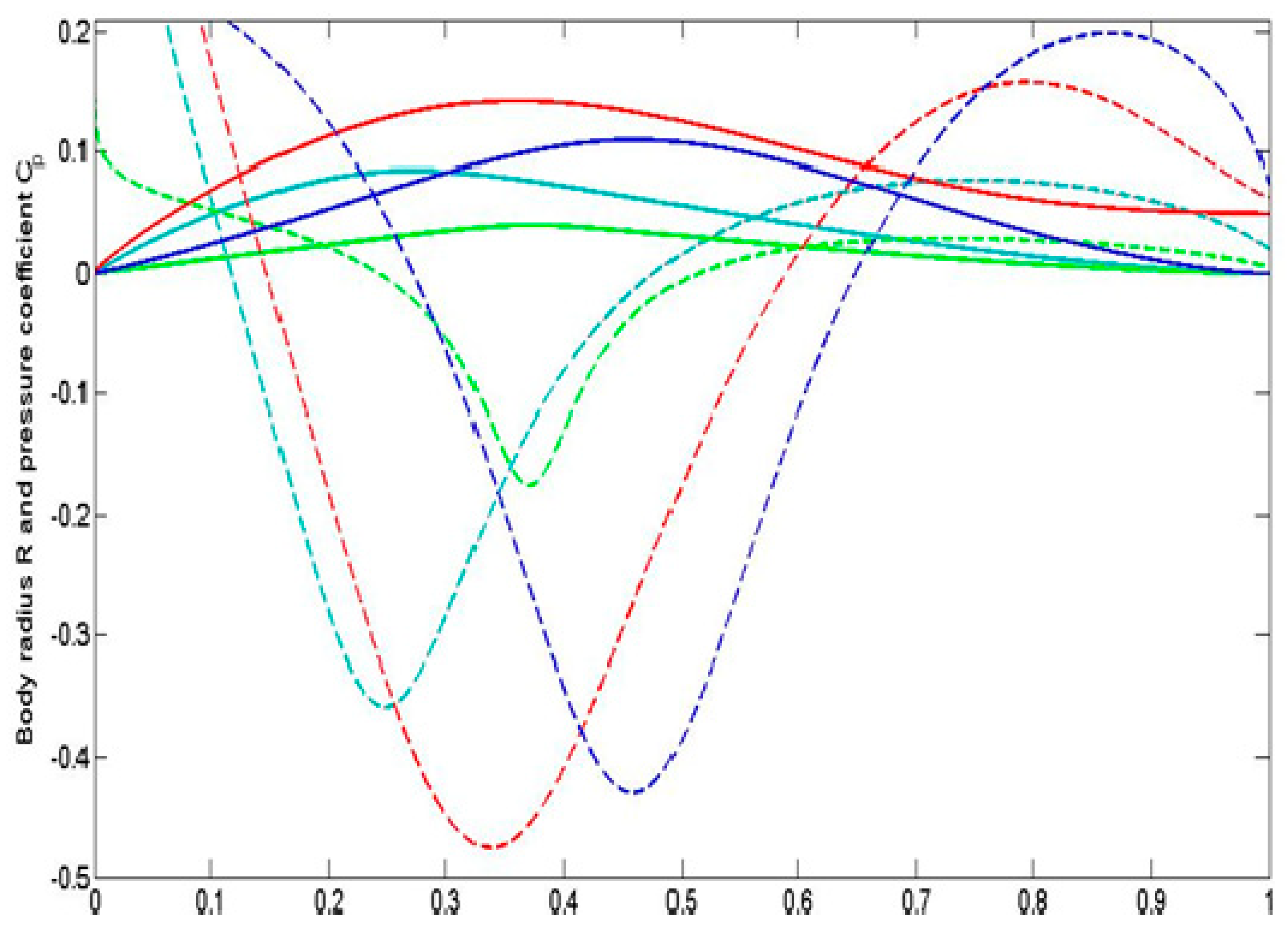
The method of calculation of shapes UA-2 and UA-2c was applied to obtain other bodies of revolution (with different thickness ratios,
D/L, and positions of their maximum thickness point;
D is the maximum diameter of the body,
L is its length) and 2D profiles as well [
22,
24,
27]. Some examples are shown in
Figure 2. The separation behavior of these shapes needs further experimental investigation, but their similarities to the bodies of aquatic animals allows us to expect an attached boundary layer, as was shown in the experiments with the rigid copies of different fish [
16]. It must be noted that all the bodies have concave tails. The shape corresponding to the smallest thickness ratio
= 0.1 also has a concave front body part (see
Figure 2) similar to the shapes of some fast-swimming fish (e.g., the Mediterranean spearfish, Indo-Pacific sailfish, black marlin or swordfish).
The attached flow pattern allows us to delay the boundary layer’s turbulent motion (see [
26,
27]) and reduce the friction drag (the pressure drag is close to zero due to the D’Alembert paradox). Then the total drag on such a body of revolution can be estimated via the following formula [
27,
29]:
where
is the kinematic viscosity coefficient of water. Equation (1) is in good agreement with the Hoerner formula [
30] for the laminar drag on the standard elongated bodies of revolution:
where the term 0.11
(D/L)2 (connected with separation) can be neglected. The body surface area
S and the Reynolds number
can be connected with the body volume V and the volumetric Reynolds number
by the empirical Hoerner equations [
30],
(see also [
22],
Figure 2).
In order to have a laminar boundary layer on the entire hull surface, the speed, length and volume of such hulls are related by the following inequality [
25,
26]:
To estimate possible drag reduction, an axisymmetric shape similar to the body of Dolphinus delphis ponticus Barab. (
L/D = 4.76) [
16] was taken to calculate the critical Reynolds number according to relationship (2). If
, the boundary layer is laminar on the entire body surface, and its drag can be estimated by (1) (see laminar curve in
Figure 3). With increasing the Reynolds number, the turbulent boundary layer zone near the tail expands and leads to the drag increasing. Simple estimations of the turbulent drag in this zone can be done with the flat plate concept [
30], and are also shown in
Figure 3. A comparison with the experimental drag measurements on the Hansen and Hoyt body [
31] shows that specially shaped hulls can ensure almost twofold lower drag.
3. Estimations of Commercial Efficiency of Neutrally Buoyant Vehicles
An estimation of the commercial efficiency of vehicles is the drag-to-weight ratio
. The minimal value of this parameter yields the maximum of tons × kilometers that can be transported by the vehicle per unit of time [
5]. With the fixed fuel (or another energy) capacity onboard, a vehicle with the maximum value of
has the maximum range. The drag-to-weight ratio can also be treated as the cost of motion, i.e., how much energy is used to move 1N of weight the distance of 1m. Usually in the literature this characteristic is related to 1 kg of mass or weight—
(see e.g., [
32]). By dividing the values in
by 9.8 (the value of gravity acceleration
g), we obtain the dimensionless criterion, coinciding with
.
For example, the mass
m of a SWATH yacht is related to the volume of an underwater hull
V by the simple formula
, where
is the water density. Taking into account that the total drag of such a vehicle is approximately two times higher than the drag
X of each underwater hull and the volumetric drag coefficient
, we can obtain the formula
where the volumetric Froude number is related to the standard one,
(based on the vehicle length
L and speed
), by the following equation:
Putting (1) and (2) into (3) allows us to obtain [
16]:
Estimation (5) can be treated as the lowest possible value of the drag–weight ratio not only for the vehicles with underwater hulls, since the drag of those with floating hulls is greater, due to the wave resistance. Equation (5) shows that the easiest means of reducing the energetic needs and pollution is to reduce the speed, to increase the volume and to use specially shaped hulls with the attached laminar flow pattern.
Equation (2) yields the limitations for the maximal mass of the neutrally buoyant vehicles with such hulls. The results of corresponding estimations are shown in
Figure 4 for water and air. According to the results shown in
Figure 4, it is possible to have a variety of fully laminar airships with very high commercial efficiency. For example, a stratospheric airship with
L/D = 20 operating at an altitude of 20 km can achieve the velocity
, and its mass can be approximately 6 t. At the attitude of 10 km, the commercial effective laminar airships are not so fast, but can be much larger. For example, an airship with
L/D = 20 can have a velocity
, and a mass of approximately 40 t. To increase the velocity of the airship, its
L/D must be higher. For example, for
, it is possible to have an effective laminar airship at
with a mass of approximately 15 t.
Airships operating at small attitudes can also be rather fast and large. For example, an airship with L/D = 20 can have the velocity and a mass of approximately 9 t. To increase the mass of the commercial effective airship, we need to decrease its velocity. For example, at L/D = 20 and velocity 5 m/s, the mass is approximately 500 t.
4. Wave Drag and Critical Froude Number
The neutrally buoyant vehicles are efficient at a small Froude number only. The estimation of the critical value of the Froude number (based on the hull length) can be found in [
25]. In particular, for a hull with a laminar attached boundary layer,
where
is the aerodynamic efficiency for airplanes or planning ships (lift-to-drag ratio). Usually,
cannot exceed the value 60 (and is much smaller for planning boats). Thus, we can use the estimation
At smaller values of the Froude number, the commercial efficiency of the neutrally buoyant vehicles (in particular, SWATH yachts) is higher than that of vehicles with dynamical weight support (like high speed planing boats).
Estimation (6) exceeds another critical Froude number, , which corresponds to the drastic increase in the wave drag on floating ships at supercritical Froude numbers. SWATH technology uses underwater hulls, and therefore this increase can be neglected, and faster yachts can be made more efficient in comparison with the standard floating boats.
5. Some Suggestions of Low Drag Swath Vehicles
The specially shaped bodies of revolution can be applied both for the underwater hulls of SWATH vehicles and for the hulls located above water. It is also possible to have a vehicle with high commercial efficiency at supercritical Froude numbers . We will give two schematic examples of SWATH ships without discussion of strength, stability and immersion. We will illustrate only the relationship between the speed and the size of vehicles with laminar underwater hulls, which provide a high commercial efficiency and the possibility of electrification.
As an example, we propose to use this technology for a fast SWATH ship (speed up to 50 m/s, weight up to 30 t). Its speed is almost two times higher in comparison with the existing SWATH vehicles (e.g., Sea Fighter FSF-1 and Francisco High-Speed Ferry). In addition, its weight-to-drag ratio is expected to be around 20. The sketch of a 1:4 model is shown in
Figure 5. Air propulsion and specially shaped hulls with the laminar-attached boundary-layer both in water and in air can be used. This concept can be employed for both small and middle-sized fast economy ferries and special ships for all seasonal operations (in particular, for high speed and seakeeping ferries and patrol ships). The use of shapes with minimal possible drag allows the reduction of the capacity of engines and their negative impact on the environment.
In the case of recreation yachts, the velocity demand is not very high, and it is possible to achieve very small values of
, provided separation could be precluded for the underwater hulls. For example, assuming the laminar flow of the entire underwater hulls and neglecting the wave drag, the value of
k could be estimated as 165 at
= 10 m/s and
V = 2 m
3. This figure is approximately three times higher than the lift-to-drag ratio of the Solar Impulse 2 plane [
19], which the rounded globe with the use of solar energy only. Such yachts can be electric, using solar cells to charge the batteries, and therefore reduce pollution. The main characteristics of the yacht are as follows:
= 10 m/s;
V = 2 m
3; weight 4 t; length 9.2 m; two underwater hulls with maximal diameter 0.92 m (
L/D = 10), with two electrical engines, propellers located on their tails and batteries; and one overwater hull of the same length, maximal diameter 2.6 m and volume 30 m
3 (see
Figure 6). It must be noted that there is no need to use very slender hulls, and there are no problems with their strength and stability.
The proposed technology could have a huge area of application, since it is economically efficient, green and comfortable (due to the high seakeeping). The Froude number is approximately 1.05, and is much higher than the critical value for the conventional ships. This means that conventional yachts of the same speed must be at least 4 times longer in order to avoid a huge increase in wave drag.


