Abstract
The propulsive performance of a bio-inspired autonomous underwater glider (AUG) with active twin undulatory wings undergoing undulatory motion was investigated by numerically solving the viscous incompressible Navier–Stokes equations, coupled with the immersed boundary method. The aspect ratio (AR) effects of the undulatory wings were studied. The simulation results showed that with the increase of AR, the thrust force generated by the active twin undulatory wings showed a linear growth, while the propulsion efficiency of the AUG increased to the peak and then decreased. The optimum magnitude of AR around 2 was obtained in the current study. The vortex structures in the wake of the active twin wings are also presented and discussed. The conclusions acquired here could provide guidance for the new conceptual design of bio-inspired AUGs.
1. Introduction
Autonomous underwater glider (AUG) is a novel type of autonomous underwater vehicle (AUV), without additional propulsion device [1]. The driving force needed by conventional AUG is mainly from regulation of net buoyancy, i.e., difference between buoyancy force and gravity force, and internal ballast block’s axial movement and rotation [2,3,4]. Contrasted with conventional AUV, AUG has extraordinary advantages, such as long range and endurance, and good maneuverability. Since the conceptual design of AUG was first proposed by Stommel [3], various types of AUG were developed and widely used in both military and civil utilizations [5,6]. However, it still faces certain challenges in the design of new conceptual AUGs. In particular, AUG usually maintains in low advancing speed, due to its nature of passive or semi-passive propulsion. It might deviate from the originally planned route through an external disturbance of strong current, failing to finish its specific mission [7,8].
Numerous efforts have been devoted to extend the capacity of AUG, by incorporating an advanced control algorithm [9], or equipping it with an additional control unit, such as an external propeller [10,11,12], inclined hydro-wings [13], etc. Recently, the authors proposed a new conceptual design of bio-inspired AUG by incorporating active twin bio-inspired wings to provide additional thrust for high-speed cruise. As inspired by the excellent locomotion abilities of swimming fish [14], the additional twin bio-inspired wings undergo either a flapping motion (e.g., periodic pitching and heaving motions) [15] or an undulatory motion (e.g., traveling wave) [16]. Studies on the propulsive performance of the bio-inspired AUG were conducted, in which the effects of the kinematic parameters were investigated. On the other hand, it was reported in the literature that the geometry of the bio-inspired wing might affect its propulsive performance, e.g., the aspect ratio (AR) effect [17,18,19,20], and our very recent work showed that the AR effect played a crucial role in hydrodynamic performance of the bio-inspired AUG with flapping motion [21].
In this study, we are going to investigate the AR effect of the bio-inspired AUG with undulatory motion. Compared to flapping motion, the bio-inspired wing turned to be flexible in undulatory motion [22,23] and the amplitude of its lateral motion was smaller than the heave amplitude in the flapping motion. In view of this, it would be convenient for an actuator design in AUG with a finite size of fuselage, where the actuator would be mounted. Preliminary actuator design of this kind of bio-inspired wing (fin) was given by Clark and Smits [24], meanwhile the AR of the wing could be varied by increasing or decreasing its spanwise length. The investigation of AR effect in the current study could provide us reasonable insight into the optimum design of bio-inspired AUG with undulatory motion and could also help us to analyze the advantages and disadvantages of the two distinct different propulsion methods, undulatory motion and flapping motion, through a comparison with the previous results acquired in our former work, which constituted the novel contribution of our current work. The structure of this paper is organized as follows. In Section 2, the mathematical problem and computation model are presented, followed by the introduction of the simulation tool and method in Section 3. The simulation results including hydrodynamic performance of the current bio-inspired AUG, as well as the corresponding flow structures are presented and discussed in Section 4. Conclusions are summarized and drawn in the end.
2. Physical Models
As shown in Figure 1, our conceptual AUG model includes two major units, i.e., the fuselage and the active twin bio-inspired wings. The bullet-like fuselage serves as the storage unit of the electrical system, the gravity center adjustment system, the actuators, etc., which provides energy supply in the normal mode, e.g., AUG gliding in quiescent water. In certain extreme conditions, such as gliding against strong current, the active twin bio-inspired wings provide additional power and generate thrust forces to ensure that the AUG maintains cruise at a high advancing speed and crosses the hostile gliding environment. Inspired from fish swimming, the twin bio-inspired wings undergo undulatory motion in the current study, and could be described as traveling wave motion. In general, the traveling wave motion of the twin wing surfaces could be expressed as:
where k represents the traveling wave number and f is the traveling wave frequency, x denotes the lateral distance from certain vertex along the chamber line to the leading edge of the wing. Effects of these kinematic parameters of the current AUG were thoroughly investigated in our previous work [16].
y(x,t) = (−0.02+0.25x−0.50x2)sin(kx−2πft)
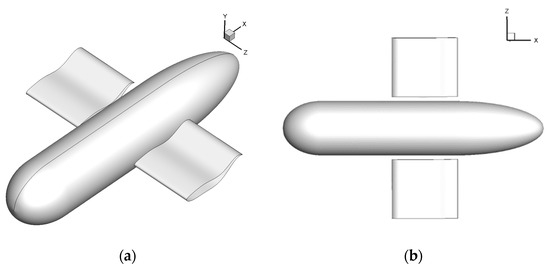
Figure 1.
Current bio-inspired autonomous underwater glider (AUG) model with active twin undulatory wings. (a) Perspective view; and (b) top view.
In the current study, we focus on the AR effect of the traveling wavy wings. Taking the chord length C of the wing as the characteristic length, the fuselage length L and diameter of its cross-section D are fixed as L = 4.0C, D = 0.83C. In order to give a more specific description of the size of our proposed bionic AUG, sizes are described with the following dimensions: the chord length of single foil C is 0.30 m, the diameter of fuselage section D is 0.25 m, and the total length of fuselage L is 1.2 m. The aspect ratio (AR) of a single rectangular wing can be expressed as
where B and S denote the spanwise length and the wet area of the wing, respectively. In this study, five different values of AR, ranging from 1.0–5.0, were selected for investigation.
AR = S/C2 = B/C
3. Simulation Tools
For the estimation of hydrodynamic interaction between the AUG and its surrounding fluid, which is a typical fluid-structure interaction problem (FSI), the immersed boundary (IB) method was employed to consider the dynamic boundary motion of the undulatory wings. In detail, by using the IB method, all computations could be conducted on the stationary Cartesian grids and the conventional grid mapping work was no longer required. On the other hand, a virtual additional force was added to the governing equation to satisfy the no-slip boundary condition on the moving boundaries. In view of these, the IB method proved to be efficient and convenient in solving typical FSI problems [25,26,27,28]. In the current simulation, the surrounding fluid was assumed to be viscous and incompressible and it was considered that the AUG’s gravity and buoyancy were equal, that is, the AUG was in hovering state. Hence, no extra consideration was needed for the effect of gravity. The non-dimensionized governing equations are
where u represents the velocity vector, P is the pressure field, and Re = ρUC/μ is the Reynolds number with ρ and μ the density and viscosity of the fluid, respectively. f is the virtual force term, which could be easily calculated as,
where Vn+1 is the immersed body’s moving velocity at the present time level t + Δt, while Vn represents the corresponding velocity at previous time level. Additionally, RHSn denotes the right-hand side of the governing equations, which includes the convective term, the viscous term, and the pressure gradient term. For the discretization of the governing equations, the second-order projection method and the finite difference method were utilized. In detail, the implicit Crank–Nicholson scheme was adopted for the dissipative term, and the Euler explicit time scheme was employed for other terms. Current simulation was conducted on a personal computer with a serial Fortran code and the accuracy of the code was fully verified and validated in our previous work [15,16,21].
According to the domain and mesh independent tests, the computation domain (taking the case of AR = 1.0 as an example) was selected as [−5C, 10C] × [−4C, 4C] × [−4C, 4C] in the x, y, and z directions, respectively. The grid size in each direction was uniform with grid spacing 0.03C, in the near region of the AUG, and gradually increased in a geometric progression to a coarser spacing of 0.1C in the far field. The grid distribution on the surface of the AUG was presented in Figure 2. The time step here was chosen as Δt = 0.001, according to our previous time independence test, which showed that the time step (Δt = 0.001) was the optimum value for maintaining a balance between the calculation accuracy and cost. According to our previous studies on a single traveling foil, optimized motion parameters for high propulsion efficiency were chosen in the current simulation, e.g., k = π. For the sake of simplicity, the Reynolds number was set to Re = 200 in the current simulation, and the surrounding flow could be considered as laminar flow, hence no additional turbulence model was applied. As a fundamental and conceptual study, we only considered the laminar situation for simplification, while the turbulence should be taken into account in future.
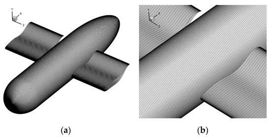
Figure 2.
Distribution on the surfaces of the AUG. (a) Grid distribution on the whole surfaces; and (b) close view of the surface.
4. Results and Discussions
A typical result is first presented in Figure 3, including the lift and drag forces experienced by all components, i.e., fuselage, left and right wings, and the corresponding parameters were set as AR = 2.0, f = 0.8 Hz, and k = π. Both the lift and the drag forces of the left and right wings overlapped with each other, due to the symmetric geometric model and the same kinematic parameters. Meanwhile, the mean values of the lift and drag forces in one single period are presented in Table 1. The mean lift forces (FL) of the twin wings and the fuselage were extremely small, which were O (10−2) and O (10−3), respectively, without taking into account the buoyancy and the gravity force. On the other hand, the twin undulatory wings produced negative mean drag forces (FD), while the fuselage obtained a positive value, which meant that the twin wings undergoing traveling wavy motion generated thrust forces to surmount the resistance force of the fuselage. Therefore, this result met our initial objective of the design.
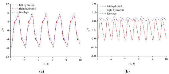
Figure 3.
Lift and drag force histories of twin wings and fuselage. (a) Lift force; and (b) drag force.

Table 1.
Mean values of the lift and drag forces of twin wings and fuselage.
4.1. Propulsive Performance of AUG with Different ARs
According to the above simulation results, the twin undulatory wings provided thrust force to the AUG, therefore, the thrust coefficient rather than the drag coefficient was adopted to evaluate the propulsive performance of the current AUG. The thrust coefficient was defined in the following, which consisted of two parts, i.e., the friction part (CTF) and the pressure part (CTP),
where U0 is the cruise velocity, S is the projection area of the wing.
The thrust force was set to T = −FD, and Tp was the pressure difference thrust force, TF was the friction thrust force. For simplicity, the propulsion efficiency of the AUG was defined as the ratio of the energy consumed in the AUG’s traveling motion versus the energy converted in generating thrust, it could be denoted as:
where, Pout and Pin represent the consumed and produced energy in the whole system of bionic AUG, respectively, Tleft and Tright are the thrust forces generated by the left and right wings respectively, pleft and pright are the pressure distributions along the twin wings’ surfaces, vleft and vright are the velocities along the y direction of the twin wings’ surfaces.
A different definition of propulsion efficiency of AUG was adopted in our previous work [16] in order to investigate the effects of kinematic parameters. In the current work, we applied the normal definition of propulsion efficiency, which was widely used in other studies [29,30].
Three typical Strouhal numbers, i.e., St = 0.5, 1.0, and 1.5, were considered in the current investigation, combined with the study on aspect ratio effects. The definition of the St number is:
where f and U0 are the undulatory frequency of the twin wings and the advancing speed of the AUG, respectively, hmax represents the wings’ maximum traveling amplitude along the y-direction and could be easily calculated from Equation (1).
St = 2hmaxf / U0
According to our previous work [16], the St number, which combines the effect of the traveling wave frequency and amplitude, plays a dominant role in the propulsion performance of the AUG. The results are shown in Figure 4. The thrust coefficient (CT) of each undulatory wings showed linear growth with an increase in AR under a fixed St number. As the St number altered from 0.5, 1.0, to 1.5, the corresponding growth ratios of CT were 1.04, 1.39, and 2.07, respectively. The friction coefficient (CTF) also showed corresponding growth with the increase of AR. In general, the larger the magnitude of AR, the higher the value of the thrust force.
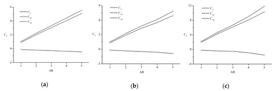
Figure 4.
Thrust coefficient of undulatory wing versus magnitude of aspect ratio (AR) under different St numbers. (a) St = 0.5; (b) St = 1.0; and (c) St = 1.5.
The pressure contours and velocity distributions in the cross-section plane of the undulatory wing of three typical cases with AR = 1.0, 3.0, and 5.0 are presented in Figure 5. As can be seen in Figure 5a, a small area of low-pressure region emerged at the lower surface of the wing tail, when it bent down, while the wider area of low-pressure region emerged when the AR value altered from 3.0 to 5.0, as shown in Figure 5b,c, respectively. Actually, the pressure difference among them played a positive role in generating thrust and the larger the pressure difference, the higher the thrust force.
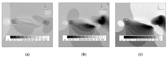
Figure 5.
Pressure contours and velocity distributions in the cross-section plane of hydrofoil with three typical AR values (a) AR = 1.0; (b) AR = 1.0; and (c) AR = 5.0.
The propulsion efficiency of the current bionic AUG versus the magnitude of AR under three St numbers is presented in Figure 6. It could be seen that the propulsion efficiency under certain St numbers, climbed to the peak value and then slowly decreased with the growth of AR, and there was an optimum AR (around 2.0 in current study) leading to the highest propulsion efficiency. Compared to our previous work (AR effect on propulsive performance of flapping foil-based AUG) [21], the highest propulsive efficiency acquired in current undulatory motion-based AUG (around 64%) was larger than the value of flapping foil-based AUG (around 45.8%) under different AR values and St numbers, demonstrating that the undulatory motion-based AUG might achieve better propulsive performance than the flapping foil-based AUG. Additionally, it could also be concluded that higher the propulsive frequency (St number), the lower the propulsion efficiency, which meant that the huge thrust force and high propulsion efficiency could not be acquired at the same time and that the conclusion was in a good consistence with previous conclusion drawn in reference [16].
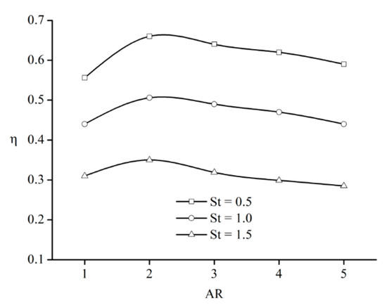
Figure 6.
Propulsion efficiency of current AUG versus magnitude of AR at different St numbers.
4.2. Vortex Structures in the Wake of Current AUG
In this subsection, the vortex structures in the wake of current AUG after four undulatory periods with three typical aspect ratios, AR = 1.0, 3.0, and 5.0, are presented and discussed. The results are shown in Figure 7, Figure 8 and Figure 9, and the vortex structures with the iso-surface value of −1.0 are represented by λ2—criterion, which was first proposed by Jeong and Hussain [31]. The corresponding kinematic parameters were set as f = 1.0 (St = 0.5) and k = π.
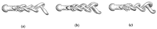
Figure 7.
Side view of the vortex structures for three typical AR values (a) AR = 1.0; (b) AR = 1.0; and (c) AR = 5.0.
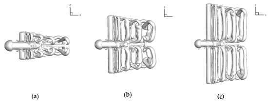
Figure 8.
View of vortex structures for three typical AR values (a) AR = 1.0; (b) AR = 1.0; and (c) AR = 5.0.
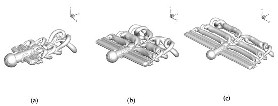
Figure 9.
View of vortex structures for three typical AR values (a) AR = 1.0; (b) AR = 1.0; and (c) AR = 5.0.
As shown in these figures, under different magnitudes of AR, the vortex rings lie in the upper and lower surface of the wings, they are separated with each other in the wake of the AUG. The spanwise length of the vortex ring that just shed from the trailing edge of the wing was very close to the span length of the wing. As the magnitude of AR increased, the spanwise length of shedding the vortex ring showed corresponding growth. As a new vortex ring shed from the wing, the former vortex ring moved downstream and its span length became narrower, as a result of the energy dissipation of the vortex rings. The higher the AR magnitude, the lesser the decrease in the spanwise length of the vortex ring. Moreover, in our previous work, the expanding angle was discussed to show its correlation to the propulsive performance of the AUG. It was concluded that with a smaller expanding angle of ring, more horizontal energy was extracted when the vortex ring shed from the wing and a better propulsive performance was achieved. As shown in Figure 7 and Figure 9, when the AR value altered from 1.0 to 5.0, the expanding angle decreased correspondingly, which might provide a reasonable explanation of the AR effects.
5. Conclusions
The aspect ratio effects of the active twin undulatory wings of the bio-inspired AUG with undulatory motion were investigated by numerically solving the incompressible viscous Navier–Stokes equations with immersed boundary method. The thrust coefficients and propulsive efficiencies of the AUG under different St numbers are presented and the vortex structures in the wake of the AUG are shown and discussed. The purpose of our study was to provide some support and guidance for the future design and optimization of bio-inspired AUGs. Here, we briefly summarized the results of the current study:
- (1)
- The thrust force generated by the active twin undulatory wings showed linear growth with the increase of AR for the cases of the St number varying from 0.5 to 1.5. The propulsion efficiency of the current AUG increased to a maximum value and then decreased with the increase of the magnitude of AR. There was an optimum AR around 2.0, corresponding to the highest propulsion efficiency.
- (2)
- The vortex rings shedding from the wings were similar to each other for the twin wings with different ARs and spanwise length of the vortex ring, which became narrow as a result of the energy dissipation. A high AR of the wing corresponded to a small spanwise length and a small expanding angle of vortex ring, resulting in little energy dissipation and good propulsive performance.
Author Contributions
Conceptualization, J.H. and Z.M.; methodology, Y.L. and J.H.; software, Y.L. and J.H.; validation, Y.L., Z.P. and Q.Z.; Formal analysis, Y.L. and J.H.; Investigation, Y.L. and J.H.; Resources, Y.L. and J.H.; Data curation, Y.L., Z.P. and Z.M.; Writing—original draft preparation, Y.L.; Writing—review and editing, Y.L. and J.H.; Supervision, J.H. and Z.M.; Project administration, J.H.; Funding acquisition, J.H. All authors have read and agreed to the published version of the manuscript.
Funding
This research was funded by the Zhejiang Provincial Natural Science Foundations (grant number LY18A020002) and Department of Education of the Zhejiang Province (grant number Y201738383).
Acknowledgments
We acknowledge the constructive and useful suggestions of three anonymous referees, whose comments have led to a substantial improvement in this paper.
Conflicts of Interest
The authors declare no conflict of interest.
References
- Ma, D.; Ma, Z.; Zhang, H.; Yao, H. Hydrodynamic analysis and optimization on the gliding attitude of the underwater glider. J. Hydrodyn. (Ser. A) 2007, 6, 005. [Google Scholar]
- Mitchell, B.; Wilkening, E.; Mahmoudian, N. Low cost underwater gliders for littoral marine research. In Proceedings of the 2013 American Control Conference, Washington, DC, USA, 17–19 June 2013; pp. 1412–1417. [Google Scholar]
- Stommel, H. The slocum mission. Oceanography 1989, 2, 22–25. [Google Scholar] [CrossRef]
- Webb, D.C.; Simonetti, P.J.; Jones, C.P. SLOCUM: An underwater glider propelled by environmental energy. IEEE J. Ocean. Eng. 2001, 26, 447–452. [Google Scholar] [CrossRef]
- Geisbert, J.S. Hydrodynamic modeling for autonomous underwater vehicles using computational and semi-empirical methods. Virginia Tech. 2007. [Google Scholar]
- Sherman, J.; Davis, R.E.; Owens, W.; Valdes, J. The autonomous underwater glider” Spray”. IEEE J. Ocean. Eng. 2001, 26, 437–446. [Google Scholar] [CrossRef]
- Ullah, B.; Ovinis, M.; Baharom, M.B.; Ali, S.S.A.; Khan, B.; Javaid, M.Y. Effect of waves and current on motion control of underwater gliders. J. Mar. Sci. Technol. 2019, 1–14. [Google Scholar] [CrossRef]
- Merckelbach, L. On the probability of underwater glider loss due to collision with a ship. J. Mar. Sci. Technol. 2013, 18, 75–86. [Google Scholar] [CrossRef]
- Su, Z.; Zhou, M.; Han, F.-f.; Zhu, Y.; Song, D.; Guo, T.-t. Attitude control of underwater glider combined reinforcement learning with active disturbance rejection control. J. Mar. Sci. Technol. 2019, 24, 686–704. [Google Scholar] [CrossRef]
- Niu, W.; Wang, Y.; Yang, Y.; Zhu, Y.; Wang, S. Hydrodynamic parameter identification of hybrid-driven underwater glider. Chinese, J. Theor. Appl. Mech. 2016, 48, 813–822. [Google Scholar]
- Zhang, X.; Ma, K.; Wei, Y.; Han, Y. Finite-time robust H∞ control for high-speed underwater vehicles subject to parametric uncertainties and disturbances. J. Mar. Sci. Technol. 2017, 22, 201–218. [Google Scholar] [CrossRef]
- Jeong, S.; Choi, H.; Bae, J.; You, S.; Kang, H.; Lee, S.; Kim, J.; Kim, D.; Lee, Y. Design and control of high speed unmanned underwater glider. Int. J. Precis Eng. Manuf.-Green Technol. 2016, 3, 273–279. [Google Scholar] [CrossRef]
- Li, Y.; Ma, Z.; Kuang, J. Hydrodynamic performances on the efficiency gliding of the underwater glider. Paper presented at The 12th International Conference on Hydrodynamics, Utrecht, The Netherlands, 24–26 August 2016. [Google Scholar]
- Triantafyllou, M.S.; Triantafyllou, G.; Yue, D.K.P. Hydrodynamics of fishlike swimming. Annu. Rev. Fluid Mech. 2000, 32, 33–53. [Google Scholar] [CrossRef]
- Li, Y.; Pan, D.; Ma, Z. The mechanism of flapping propulsion of an underwater glider. J. Hydrodyn. 2016, 28, 918–921. [Google Scholar] [CrossRef]
- Li, Y.; Pan, D.; Zhao, Q.; Ma, Z.; Wang, X. Hydrodynamic performance of an autonomous underwater glider with a pair of bioinspired hydro wings–a numerical investigation. Ocean Eng. 2018, 163, 51–57. [Google Scholar] [CrossRef]
- Dong, H.; Mittal, R.; Najjar, F. Wake topology and hydrodynamic performance of low-aspect-ratio flapping foils. J. Fluid Mech. 2006, 566, 309–343. [Google Scholar] [CrossRef]
- Shao, X.; Pan, D.; Deng, J.; Yu, Z. Numerical studies on the propulsion and wake structures of finite-span flapping wings with different aspect ratios. J. Hydrodyn. 2010, 22, 147–154. [Google Scholar] [CrossRef]
- Hu, J.; Xiao, Q. Three-dimensional effects on the translational locomotion of a passive heaving wing. J. Fluids Struct. 2014, 46, 77–88. [Google Scholar] [CrossRef]
- Xiao, Q.; Hu, J.; Liu, H. Effect of torsional stiffness and inertia on the dynamics of low aspect ratio flapping wings. Bioinspir. Biomim. 2014, 9, 016008. [Google Scholar] [CrossRef]
- Li, Y.; Pan, D.; Ma, Z.; Zhao, Q. Aspect Ratio Effect of a Pair of Flapping Wings on the Propulsion of a Bionic Autonomous Underwater Glider. J. Bionic Eng. 2019, 16, 145–153. [Google Scholar] [CrossRef]
- Xiao, Q.; Sun, K.; Liu, H.; Hu, J. Computational study on near wake interaction between undulation body and a D-section cylinder. Ocean Eng. 2011, 38, 673–683. [Google Scholar] [CrossRef]
- Xiao, Q.; Liu, W.; Hu, J. Parametric study on a cylinder drag reduction using downstream undulating foil. Eur. J. Mech. B-Fluids. 2012, 36, 48–62. [Google Scholar] [CrossRef]
- Clark, R.P.; Smits, A.J. Thrust production and wake structure of a batoid-inspired oscillating fin. J. Fluid Mech. 2006, 562, 415–429. [Google Scholar] [CrossRef] [PubMed]
- Mittal, R.; Iaccarino, G. Immersed boundary methods. Annu. Rev. Fluid Mech. 2005, 37, 239–261. [Google Scholar] [CrossRef]
- Pan, D.; Liu, H.; Shao, X. Studies on the oscillation behavior of a flexible plate in the wake of a D-cylinder. J. Hydrodyn. 2010, 22, 132–137. [Google Scholar] [CrossRef]
- Pan, D.; Shao, X.; Deng, J.; Yu, Z. Simulations of passive oscillation of a flexible plate in the wake of a cylinder by immersed boundary method. Eur. J. Mech. B-Fluids. 2014, 46, 17–27. [Google Scholar] [CrossRef]
- Pan, D.; Deng, J.; Shao, X.M.; Liu, Z. On the Propulsive Performance of Tandem Flapping Wings with a Modified Immersed Boundary Method. Int. J. Comput. Methods. 2016, 13, 1650025. [Google Scholar] [CrossRef]
- Shen, L.; Zhang, X.; Yue, D.; Triantafyllou, M. Turbulent flow over a flexible wall undergoing a streamwise travelling wave motion. J. Fluid Mech. 2003, 484, 197–221. [Google Scholar] [CrossRef]
- Shao, X.; Pan, D.; Deng, J.; Yu, Z. Hydrodynamic performance of a fishlike undulating foil in the wake of a cylinder. Phys. Fluids. 2010, 22, 111903. [Google Scholar]
- Jeong, J.; Hussain, F. On the identification of a vortex. J. Fluid Mech. 1995, 285, 69–94. [Google Scholar] [CrossRef]
© 2020 by the authors. Licensee MDPI, Basel, Switzerland. This article is an open access article distributed under the terms and conditions of the Creative Commons Attribution (CC BY) license (http://creativecommons.org/licenses/by/4.0/).