1. Introduction
A geometry with slots or pores can be used to enhance energy dissipation and in turn reduce the environmental impact. Currently, porous structures have been widely constructed in the coastal and offshore industries for the purpose of shore production or reduction of the wave forces. To achieve a good understanding of the hydrodynamic properties related to porous structures, the behavior of a porous body in waves has attracted considerable interest among researchers.
So far, various studies have been conducted on this subject due to its importance in practical engineering. The porous elements are included in many offshore structures, such as fish cages, wave breakwaters, and offshore platforms equipped with damping devices. The porous geometry was commonly assumed to be with fine pores and thin in thickness. A linear or quadratic resistance law was used to relate the pressure drop to the crossflow velocity. Linear relations between the pressure drop across the porous geometry and the traversing velocity were derived by researchers, e.g., by using Darcy’s law [
1] or by using the convection neglected and porous effect modelled Euler equation [
2]. The linear laws were adopted in many studies in assessing the functional performance of porous breakwaters of different types, such as vertical or submerged horizontal porous plates, perforated caissons, and porous columns [
3,
4,
5,
6,
7,
8]. Based on a linear resistance law, Zhao et al. [
9] examined the various hydrodynamic identities for porous structures. In addition, Dokken et al. [
10] formulated the wave diffraction/radiation problem of a porous geometry of an arbitrary shape by a set of integral equations. On the other hand, to model the flow separation through porous materials, quadratic laws were proposed in some studies, such as Molin [
11] and An and Faltinsen [
12]. The quadratic pressure drops were considered by researchers in prediction of the added mass and the damping coefficients for a porous stabilizer, plate, or disc undergoing forced motions as well as the wave force on thin porous sheets. Examples include Molin and Remy [
13] and Mackay et al. [
14].
The application of a porous material can lead to a low level of wave transmission and reflection. In the meantime, it can also reduce the wave impact on the enclosed structure. A vertical column has been an essential component of various offshore structures. Previous studies indicated that the linear wave force on an impermeable column can be reduced significantly by surrounding it with porous geometries (see Wang and Ren [
15] for example). Besides the linear wave force, the nonlinear wave force is also closely relevant to the proper design of offshore structures. The nonlinear hydrodynamic properties related to a vertical column or a column array in open seas has been investigated in some studies spanning from analytical studies to model tests and numerical modelling, such as references [
16,
17,
18,
19,
20]. However, the nonlinear wave interaction with a vertical column shielded by an exterior porous shell has been rarely investigated so far. The present study intends to contribute in this direction.
In this study, the mean drift wave force, which is of the second order from the perspective of the wave steepness, on a system consisting of an interior impermeable cylinder and an exterior porous shell is investigated. Definition of the concentric porous cylinder system is given in
Figure 1. The potential flow theory is adopted, and a linear resistance law is assumed at the porous shell. Within the framework of the potential flow theory, a non-linear analysis can be achieved by applying a perturbation procedure, in which the velocity potential, wave force, and other physical quantities of interest are expressed in linear and higher-order components through some small parameters, and the wave steepness is normally used as the perturbation parameter. Based on the idea of the perturbation expansion, the mean drift wave force normally represents a time-independent force component which is proportional to the square of the wave steepness. In this study, semi-analytical solutions to the mean drift wave force on the system shown in
Figure 1 are developed by two alternative ways. One is based on the direct pressure integration, while the other is based on the application of the momentum conservation theorem in the fluid domain. Unfortunately, solutions to the mean drift wave force on a vertical column shielded by an exterior porous shell have been rarely developed in the previous studies, and the research achievement in this study can help fill this gap. Based on the developed solutions, detailed numerical studies are performed. The effect of the exterior porous shell on the mean drift wave force on the interior column is examined, and the characteristics of the mean drift wave force on such a system are explored.
Following the introduction, the mathematical model and the solution of the velocity potential are introduced in
Section 2, followed by a calculation of the mean drift wave force in
Section 3. The parametric study is carried out thereafter in
Section 4, with conclusions drawn in
Section 5.
2. Mathematical Model and Solutions to the Velocity Potential
Let us consider a bottom-mounted, surface-piercing, and impermeable cylinder of radius
a situated in a water of a finite depth
d. This cylinder is surrounded by an exterior cylindrical shell of radius
b. Both of them are fixed rigidly at the horizontal sea bottom. The exterior shell is porous and considered to be thin in thickness. As shown in
Figure 1, a cylindrical coordinate system is employed with its origin located at the center of the interior cylinder and at the still free surface. The
z-axis directs vertically upward and coincides with the vertical axis of the cylinders.
Within the framework of the potential flow theory, the flow is assumed to be inviscid, incompressible and irrotational. Thus, the flow field can be described by a scalar velocity potential
, satisfying Laplace’s equation,
Regular incident waves are concerned in this study. The incident wave is time-harmonic with an angular frequency
ω. Then, the time factor can be separated out, and the velocity potential is expressed as
where “Re” denotes the real part of a complex expression;
.
The entire fluid domain is then divided into two sub-domains: the interior region Ω
1 (
a ≤
r ≤
b), and the exterior region Ω
2 (
r ≥
b). Hereinafter, the velocity potentials in the interior and exterior regions are denoted by
and
, respectively. Besides Laplace’s equation, appropriate boundary conditions on the free surface and the seabed are also required, given by
where
g is the acceleration due to gravity.
The fine-pore assumption is adopted, and a linear pressure drop assumption (see references [
1,
2] for example) is applied as in many previous studies. Then, the boundary condition on the porous shell can be expressed as
where
k is the wave number satisfying the dispersion relation
.
G0 is a linearized porous effect parameter. On the surface of the interior impermeable cylinder, it is required that
A train of incident waves, of an amplitude
A and an angular frequency
ω, propagates in the direction of the positive
x-axis to encounter the system. The incident velocity potential is then expressed as
in which
stands for the Bessel function of order
m;
is an orthonormal function given at the interval [−
d, 0] and defined by
The presence of the system can result in diffraction of the incident waves in the exterior region. Then, the velocity potential in the exterior region can be decomposed as
in which
denotes the diffraction potential in the exterior region. In addition to the boundary conditions in Equations (3), (4), and (5),
also needs to satisfy the Sommerfeld radiation condition in the far field. That is,
The solution of the velocity potential is then obtained following the way shown in [
15]. The separation of variables method is used, and the expressions of
and
can be written as
in which
In Equation (12),
Am,
Bm and
Cm are unknown coefficients;
Hm(
kr) is the Hankel function of the first kind of order
m. The velocity potential given in Equation (11) satisfies Laplace’s equation and Equations (3) and (4). The unknown coefficients in these expressions can be determined by imposing the boundary condition at
r =
a and
r =
b (see Equations (5) and (6)). Then,
Am,
Bm and
Cm are derived as
in which
In Equations (13) and (14), the prime appearing in the superscript denotes the derivative with respect to the argument.
3. Calculation of the Mean Drift Wave Force Based on Direct Pressure Integration
Based on the derived velocity potential, various quantities of engineering interest can be determined. The mean drift wave force can be computed from the quadratic products of the quantities derived from the linear wave theory. The calculation of the mean drift wave force based on the direct pressure integration, i.e., the near-field formulation, is quite straightforward. Referring to the well-established second-order theory, the mean drift wave fore on the interior column,
, can be determined according to
In Equation (15),
Sc stands for the undisturbed wetted surface of the column; Γ
c denotes the intersection of
Sc with mean free surface (
z = 0);
n = (
nx,
ny,
nz)
T is the normal vector on the boundary surface which is positive when pointing out of the fluid domain. The analysis of the mean drift force on a porous geometry is similar to that of an impermeable one. This was done by some researchers, such as the authors of references [
9,
10]. As for the present system, the mean drift wave force on the porous shell,
, is due to the difference between the fluid pressure on its outer and inner surfaces. Then, we have
in which an asterisk in the superscript represents the complex conjugate;
and
represent the outer and inner undisturbed wetted surfaces of the porous shell;
and
stands for the intersection of
and
with the mean free surface (
z = 0). For vertically axisymmetric bodies, the surface integrals in Equations (15) and (16) can be simplified by integrating in
θ and applying the orthogonality. Making use of Equations (5), (6), and (11), we can have
and
In Equations (17) and (18),
is defined by
Then, the total mean drift wave force on the system,
, can be expressed as a sum of
and
, i.e.,
4. Calculation of the Mean Drift Wave Force Based on the Application of the Momentum Conservation Theorem
Besides the approach of direct pressure integration, the mean drift wave force can also be obtained by applying the momentum conservation theorem in the entire fluid domain, namely the far-field formulation. By using the kinematic transport theorem and Gauss’ theorem, the total linear momentum along the direction of wave propagation can be expressed as
in which
is the momentum;
P is the fluid pressure;
Sb represents a summation of the wetted surface of the column as well as the inner and outer wetted surface of the porous shell, respectively, i.e.,
;
S∞ is a circular cylindrical control surface at a large distance from the system;
and
represent the overall free surface and the overall sea bed in the entire fluid domain, respectively;
u =
= (
u,
v,
w)
T is the vector of the fluid particle velocity;
Un denotes the normal velocity of the boundary surface. On
Sf and
Sd, it is required that
u·n −
Un = 0. In addition, the entire system and the control surface at infinity are fixed, yielding
Un = 0 on
Sb and
S∞. On
Sd, we have
nx = 0. In the meantime, on the free surface, the fluid pressure
P is equivalent to the atmospheric pressure which is assumed zero. Then, based on Equation (21), the wave force on the system,
F, can be related to the total linear momentum in the fluid domain. That is,
When the time average is taken, and the periodicity is invoked, the last term on the right-hand side of Equation (22) gives no contribution. Then, the mean drift wave force on the system is
in which
In Equation (24), an over bar indicates averaging over a wave period. In the far field, using asymptotic expressions for Hankel functions, the diffraction potential for large
r can be expressed in an asymptotic form. Then, we have
in which
Inserting Equation (25) into Equation (24a) and applying the stationary phase method to the double integral, Equation (24a) can be rewritten as
Combining Equations (5), (6), and (11), Equation (24b) can be rewritten as
in which
From the derivation of Equations (23), (27), and (28), it is noted that when a vertical column is shielded by an exterior porous shell, the far-field formulation consists of a conventional part similar to that on an impermeable body, i.e., , as well as an additional part caused by the energy dissipation through the external porous shell, i.e., .
In this section, solutions to the mean drift wave force on the system are derived by applying the momentum conservation theorem in the entire fluid domain. Actually, if the momentum conservation theorem is applied in a finite fluid domain surrounding the structure, solutions can also be derived. Then, the quantities on a control surface, which is a distance away from the structure, are involved in the calculation. The derivation of the semi-analytical solutions to the mean drift wave force on structures using control surfaces can be found in some previous studies, such as Cong et al. [
21].
5. Numerical Results and Discussion
In the previous sections, two different formulations have been proposed for the mean drift wave force on a concentric porous cylinder system. When the near-field formulation is used, the mean drift wave force on the interior column and the exterior shell can be evaluated based on Equations (17) and (18), respectively. The force components involved in the far field formulation can be evaluated according to Equations (27) and (28), respectively. Hereinafter, the factor
ρgaAA* is introduced for the normalization, and the symbols
,
,
,
and
are used to denote the normalized mean drift wave force. The convergence of the wave force based on the two proposed formulations both depends on the number of Fourier modes. In the numerical algorithm, in total, 2
M + 1 Fourier modes (from the order (−
M) to the order
M) have been included. To examine the convergence of the present solution with respect to
M, calculations are performed for the case of
b = 2
a,
d = 3
a and
G0 = 0.1.
Table 1 and
Table 2 list the normalized mean drift wave force on the interior column, i.e.,
, and the exterior porous shell, i.e.,
, as a function of
M for a set of wave frequencies. The variation of
and
, which are the force components involved in the far-field formulation, with respect to
M are given in
Table 3 and
Table 4. In these tables, “NF” and “FF” refer to the results evaluated according to the near-field and the far-field formulations, respectively. Moreover, the term
ka represents the product by the wave number
k and the radius
a. In addition, in the tables, positive and negative signs mean that the mean drift wave force is along the positive and negative
x-directions, respectively. Inspecting the results listed in these tables, it appears that the two models both possess good convergence characteristics. Thirty-one Fourier modes (
M = 15) is sufficient to achieve a convergent result, and therefore,
M = 15 is adopted in the subsequent computations. Meanwhile, in order to confirm the validity of the present solution, a comparison between the results based on the two formulations is made (see
Table 5). Comparison confirms the good agreement between the convergent results based on the two formulations.
With the validation of the developed model, a parametric study is then performed. The far-field formulation is adopted firstly. As shown in Equation (23), if the far-field formulation is used, the total mean drift wave force on the system consists of a component associated with the quantities in the far-field, i.e.,
, as well as an additional component caused by the energy dissipation through the porous shell, i.e.,
. The effect of the porous parameter
G0 on
,
, and
is shown in
Figure 2 with
b = 2
a and
d = 3
a. In
Figure 2,
G0 = 0 corresponds to the situation when the exterior shell becomes impermeable. When
G0 = 0,
remains zero, and
coincides with
. As shown in
Figure 2a,b, when
G0 > 0,
and
in general make opposite contributions to the total force on the system in which the dominant part is
. In the meantime, from
Figure 2c, it is found that, when the exterior shell becomes porous, i.e.,
G0 > 0, the trend of the mean drift wave force on the system is different from that when
G0 = 0, as there are a series of small peaks appearing around
ka = 0.678, 1.341, 1.979, 2.588, etc. The occurrence of these small peaks is explained as below. The continuity of the fluid velocity between the inner and the outer regions is fulfilled by Equation (5). Based on Equation (5), the normal fluid velocity across the porous shell can be expressed as
in which
In Equations (30) and (31),
is the
mth order Fourier component of the normal fluid velocity across the porous shell;
and
are the Fourier components of the velocity potential in the interior and the exterior domains, respectively. It is interesting to find that as
ka gets close to 0.678, 1.341, 1.979 and 2.588 (when
b = 2
a and
d = 3
a),
ub,±1,
ub,±2,
ub,±3, and
ub,±4 approach zero, respectively. Equation (5) ensures the continuity of the fluid velocity between the inner and outer regions. From Equation (31), it is found that at these wave frequencies, Fourier components of the velocity potential of the order ±1, ±2, ±3, ±4, etc. are continuous as well between the inner and outer regions. It means that to these components of the incoming waves, the porous shell is no longer a barrier but, on the contrary, thoroughly “transparent,” permitting them to transmit across without any diffraction or dissipation. In this mechanism, the porous shell acts as a “wave filter” for special frequencies, thereby certain components of the incident waves cannot be dissipated by the shell. Then, the dissipation effect of the porous shell is significantly weakened at these wave frequencies, triggering an apparent diminishment of
in magnitude (see
Figure 2b). In the meantime, as not all the components of the incoming waves can be diffracted by the shell around these special wave frequencies, the diffracted waves in the far filed would be affected, leading to the small oscillations of
around these wave frequencies (see
Figure 2a). As a result, due to the aforementioned large diminishment of
, local enhancements of the total mean drift wave force on the system arise at these wave frequencies.
The near-field formulation is then adopted. The effect of the porous parameter
G0 on the mean drift wave force on the interior column and the exterior shell, i.e.,
and
, is shown in
Figure 3 with
b = 2
a and
d = 3
a. In
Figure 3a, “SC” corresponds to the situation when the exterior shell is removed and the interior column is exposed directly to the action of the incoming waves.
Figure 3a illustrates that with the shielding of a slightly porous shell, the mean drift wave force on the interior column is significantly reduced in comparison to that without the shell. In addition, in
Figure 3a, peaks can be observed around
ka = 1.341, 1.979, and 2.588. As mentioned before, this is due to the reason that around these wave frequencies, certain components of the incoming waves can completely transmit into the inner region. Then, the wave action upon the interior column is enhanced, as demonstrated by the peaks. From
Figure 3a, it is also interesting to find that around
ka = 0.678,
is close to zero, which can be explained as below. Around
ka = 0.678, the waves transmitting into the inner region are dominated by the Fourier components of the order ±1, resulting in a phase difference of π between the lee side and the weather side of the interior column. In addition, at
ka = 0.678, the wave length is long enough when compared to the radius of the interior column, and the wave diffraction by the column is relatively negligible in comparison to the incident waves. Therefore, at this wave frequency, the wave run-up along the column distributes almost anti-symmetric with respect to the
y-axis. Then, the quadratic fluid pressure, which is proportional to the square of the fluid velocity, on the lee side of the column is almost the same as that on the weather side, leading to that the mean drift wave on the column is close to zero. In
Figure 3b, it appears that the mean drift wave force on the shell is much larger in magnitude than that on the column, and the results of
are close to those of
. It suggests that if the near-filed formulation is adopted, the total force on the system is dominated by
. The effect of
G0 on
is not apparent for long incident waves. However, for short incident waves, the effect is notable since
in general decreases as
G0 increases.
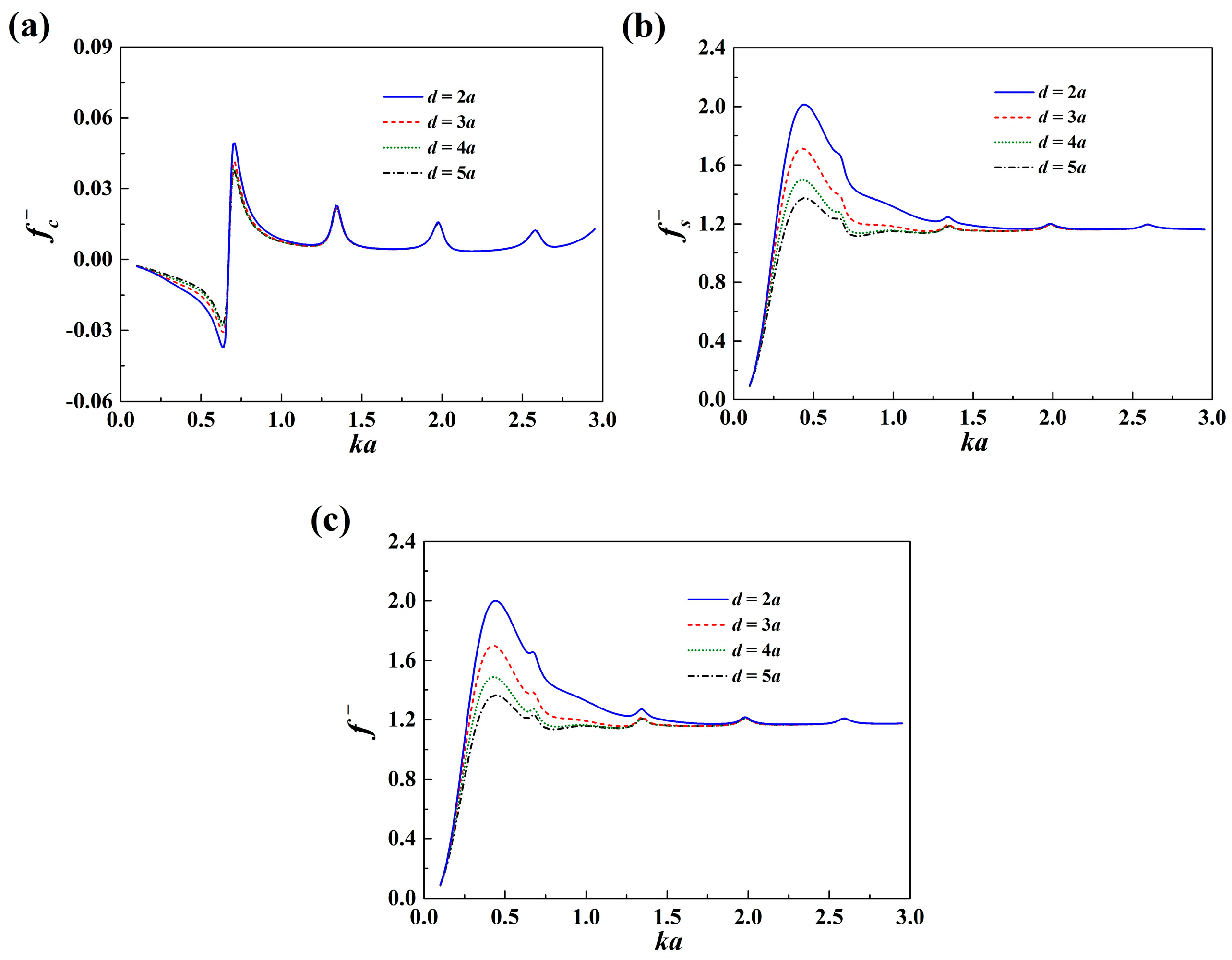
The effect of the radius of the exterior porous shell and the effect of the water depth on the mean drift wave force acting on the impermeable column, the porous shell and the system as a whole are shown in
Figure 4 and
Figure 5, respectively. As shown in
Figure 4, the total mean drift wave force on the system increases with the increase of
b. This is due to that the system interacts with more incoming waves as the radius of the exterior porous shell increases. It is also found that the frequencies of the small peaks move to the high-frequency region as the shell gets closer to the enclosed column. In
Figure 5, the effect of the water depth gets less apparent as
ka increases. This is due to the fact that in short incident waves, the fluid velocity decays quickly downward along the gravity direction.
6. Conclusions
The wave interaction with a concentric porous cylinder system, consisting of an interior impermeable column and an exterior slightly porous thin shell, is described. The exterior shell is assumed to have fine pores, and a linear resistance law is used to relate the pressure drop across the porous shell with the normal velocity. This study aims to investigate the effect of the exterior porous shell on the nonlinear mean drift wave force on the interior column. The main conclusions of this study are summarized as follows:
(1) Two different formulations have been derived for the calculation of the mean drift wave force on such a system. One is based on the direct pressure integration, i.e., the near-field formulation, and the other is based on the application of the momentum conservation theorem in the fluid domain, i.e., the far-field formulation. It is found that the results based on the two formulations agree exactly with each other.
(2) The far-field formulation of the mean drift wave force for the present problem consists of two parts, i.e., a conventional part, which is contributed by the quantities in the far field (similar to that on impermeable bodies), as well as an additional part caused by the energy dissipation across the porous shell. The former part dominates the total mean drift wave force on the system.
(3) The mean drift wave force on the interior column shielded by an exterior porous shell can be largely reduced when compared to that without the exterior porous shell. With the exterior shell being porous, the trend of the mean drift wave force on the system is different from that when the exterior shell is impermeable, as there is a series of small peaks riding on the main trend. It is found that these small peaks occur when certain propagation modes of the fluid velocity satisfy a no-flow condition at the porous shell. Then, the porous shell cannot dissipate energy from these modes, enhancing the wave impact upon the system.
The characteristics of the mean drift wave force on concentric porous cylinders are explored in this study. This reveals that, due to the presence of the porous shell, the interior column does not experience any mean drift wave force at specific conditions. The conclusions achieved in the present study are important references to subsequent studies concerning floating systems, which can be further explored as a future work.


