Article

Long-Term Strength of Alkali-Activated Mortars with Steel Fibres Cured in Various Conditions

1
School of Civil, Environmental and Mining Engineering, the University of Western Australia, Perth WA 6009, Australia
2
School of Civil Engineering, Chongqing University, Chongqing 400045, China
*
Author to whom correspondence should be addressed.
J. Mar. Sci. Eng. 2020, 8(4), 278; https://doi.org/10.3390/jmse8040278
Submission received: 15 February 2020 / Revised: 7 April 2020 / Accepted: 10 April 2020 / Published: 13 April 2020
(This article belongs to the Special Issue Sustainable Concrete in the Marine Environment)

Abstract

:
The long-term effect of extreme conditions, such as high concentrations of CO2, a combination of chloride and air, and sulfuric acid, on the performance of steel fibre reinforced alkali-activated fly ash and slag (AAFS) mortars was investigated. The selected conditions simulated the long-term exposure to the marine environment and had an influence on both the matrix and the fibres. Four AAFS mixes were analysed alongside a control ordinary Portland cement (OPC) mix. Mechanical properties such as the compressive strength, elastic moduli and ductility indices, as well as microscopic analyses were carried out. It was found that the AAFS was stable in most of the conditions. The primary way for its reduction in strength was through the neutralisation of pore fluids and the leaching of sodium cations. The addition of the short fibres could reduce the ingress of deleterious materials by limiting the development of cracks and allowing for the efficient use of higher activator ratios. The fibres were susceptible to corrosion by chloride and acid attacks. The relatively chemically stable environment of the AAFS provided protection to the embedded fibres. Based on this study, in a very aggressive environment, a combination of 1%–2% fibre by volume, with a high activator content in the AAFS mortar, could be the most suitable.

1. Introduction

Alkali-activated materials (AAM) are produced by mixing a selection of precursors such as fly ash, ground granulated blast-furnace slag (GGBS) with an alkaline source in solid or solution forms. What is considered industrial wastes or by-products can be utilised to produce cementitious materials without the high-temperature calcination process used in the cement production. This reduces the CO2 emission and the extraction of natural resources. The microstructure of the alkali-activated fly ash (AAFA, or “geopolymer” as used in various sources [1]) is dense, and due to the low calcium content, is less susceptible to the decalcination reaction. However, the AAFA composites have relatively low compressive strengths, especially at the early age, as a result of the incomplete dissolution of fly ash at room temperature [2]. Therefore, curing at elevated temperatures was typically required. The effect of curing temperature and duration has been extensively studied [3,4,5]. Alternatively, GGBS can be added to enable ambient temperature curing and to improve the compressive strengths and pore refinement. However, at a high dosage the addition of GGBS could have adverse effects, such as reduced workability, more rapid setting [6], and increased risk of decalcination. The replacement ratio is typically maintained at around 50% for optimum performance [7,8]. It was found the alkali-activated fly ash and slag (AAFS) mortars have lower elastic moduli and are more brittle compared to the models used for ordinary Portland cement (OPC) [7]. The addition of steel fibre could mitigate this problem. Additionally, fibre reinforcement could significantly improve the performance of the composite under flexural loading [9], making it desirable in high-rise buildings or seismic regions.
The reaction products in alkali-activated fly ash and GGBS (AAFS) composites vary from those in ordinary Portland cement (OPC) composites. The most noticeable difference is the absence of portlandite (Ca(OH)2) [10]. The AAFS also has more minor phases such as the hydrotalcite (M5AH13) and hydrogarnet (C6AFS2H8). Ettringite ( C 6 A S ¯ 3 H 32 ) is typically observed due to the use of gypsum in the GGBS, but the monosulfate hydrate ( C 4 A S ¯ H 18 ) phase is not seen [10]. In OPC, the monosulfate hydrate could transform into ettringite in a moist environment, causing expansion and cracking in the matrix. Therefore, the AAFS is considered to have superior durability than OPC. Its performance in three conditions, namely, chloride-rich, sulphate-rich, and CO2-rich environments is discussed.
A chloride-rich environment is typically found in the sea or brackish waters. The presence of chloride ions has damaging effect on the embedded steel rather than the concrete itself. The AAFS is relatively stable in chloride-rich environments [11]. It was found that the higher concentration of sodium in the environment reduced the rate of diffusion of sodium-based activators into the surrounding liquid, thus improving the performance [12]. Comparable or higher compressive strengths, as well as lower shrinkage results, were observed compared to specimens cured in ambient conditions (23 ± 2 °C and 95% humidity).
The sulphate is generally supplied through the sulfuric acid, the sodium sulphate or magnesium sulphate. The AAFS is relatively stable under sulphate attack, with no formation of delayed ettringite due to the lack of tricalcium aluminate (C3A) [13,14]. The magnesium sulphate is an exception, due to its tendency to damage the calcium-silicate-hydrate (C-S-H) and produce magnesium-silicate-hydrate (M-S-H). The aluminium-substituted C-S-H (C-A-S-H) does exist in AAFS systems, therefore it is at risk of decalcification from the Mg2+. In marine environments, the Mg2+ only accounts for 0.127% of the seawater by weight, compared to SO42− at more than double the amount (0.265%) [15]. Despite the stable chemical structure against the sulphate attacks, considerable strength reductions were observed, mainly due to the leaching of alkalis into the liquid [16].
The reaction of AAFS under carbonation differs significantly from that of the OPC. In OPC, the insoluble calcium carbonate (CaCO3) is the main reaction product, whereas the soluble sodium carbonate (Na2CO3) is formed in AAFS specimens. This means that the sodium carbonate is free to migrate through the pores and form a layer of salt on the surface. This will not only affect the appearance of the structure but also results in the reduction of pore alkalinity. At a pore pH value below 9, a significant reduction in the sodium attached to the pore structure was observed [17,18], which had a negative impact on the structural integrity [19,20].
A smaller number of studies was available on the performance of fibre reinforced AAM subjected to different conditions. It was found that the addition of a small quantity of steel fibres (up to 1%) further improved the durability of geopolymer concrete (GPC) compared to OPC in terms of water absorption and porosity [21]. The fibre-reinforced GPC (FRGPC) had similar levels of performance as OPC in both chloride and sulphate attacks, but a significantly lower mass loss (2% versus 27%) when subjected to 3% H2SO4 for 6 months [21]. Another study found that the FRGPC had excellent resistance to magnesium sulphate due to the stable chemical structure and the absence of gypsum and ettringite [22]. They also found that the addition of steel fibre reduced the chloride penetration, likely due to less shrinkage cracking and an overall denser structure. However, from another study [23], FRGPC showed signs of corrosion before those without fibres, possibly due to the increased permeability as a result of the fibres. The overall mass loss of FRGPC was comparatively lower, due to its improved resistance to crack propagation.
The AAFS is an environmentally friendly alternative to the OPC. Its better chemical resistance also makes it a suitable option to be used in the aggressive marine environments. However, the strength and durability of alkali-activated materials are heavily influenced by many factors, from the mix design to the surrounding environments. From the above literature review, it can be seen that the long-term effect of curing environments on the strength properties of steel-fibre reinforced AAFS has not been quantified. This paper presents an experimental program with four AAFS mixes alongside one OPC control mix. For each mix, four steel fibre dosages were used (0%, 1%, 2% and 3% by weight). The twenty mixes were cured in the ambient room (23 ± 2 °C and 95% humidity), carbonation chamber (1% CO2), a sodium chloride bath and sulfuric acid bath. These conditions simulated the extreme and long-term exposure to the marine environment. The strength properties, specifically, the compressive strengths, elastic modulus, and ductility, were compared at 28 days and 300 days. X-ray diffraction (XRD) and scanning electron microscope (SEM) were used to support the results and observations. The results improve the confidence of using this sustainable and high-performance composite material in harsh environments, such as the coastal and offshore regions in Australia.

2. Experimental Program
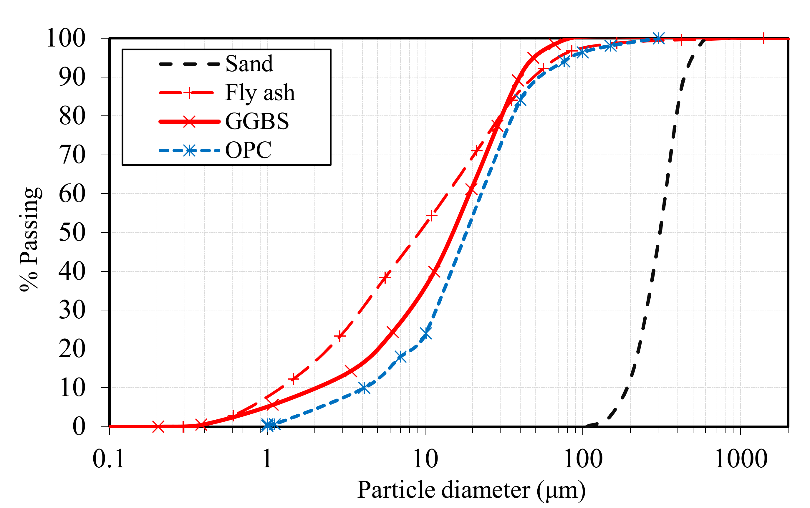
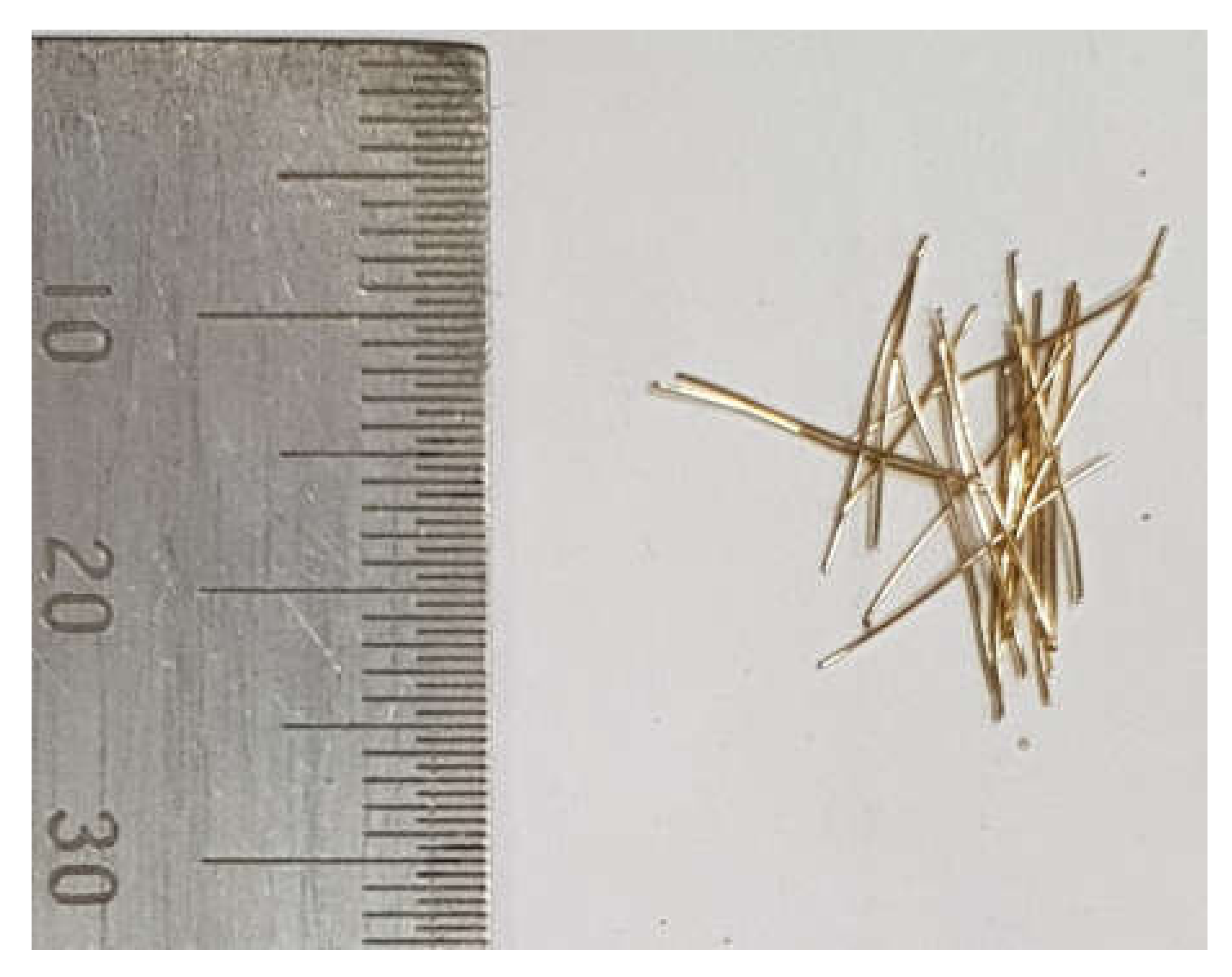
2.1. Materials

The AS 3582.1:2016 [24] Grade 1 fly ash and a commercially available GGBS were used as the precursors for the AAFS mortar mixes. A general purpose OPC was used in the control mix. The oxide analysis results of the three materials are shown in Table 1. The fly ash had only 7.0% CaO compared to 43.2% in the GGBS and 65.1% in the OPC. Therefore, it was expected that the risk of decalcification was significantly lower in the AAFS with a high dosage of fly ash. Dune sand was used as the fine aggregate. The particle size distribution curves of the binders and sand are shown in Figure 1. The d90 values for sand, fly ash, GGBS, and OPC were 440, 50, 40, and 55 μm, respectively.
A hybrid activator consisting of a 12 M sodium hydroxide solution and a commercially available sodium silicate solution was used. The sodium silicate solution had a SiO2 to Na2O ratio (Ms) of 2.3 and a specific gravity of 1.5. The solid accounted for 43% by mass of the solution.
Short straight steel fibres of length 10 ± 1 mm and diameter 0.12 ± 0.01 mm, which gave an aspect ratio of 80, were used, as shown in Figure 2. The tensile strength was at least 3000 MPa.

2.2. Mix Composition and Mixing Procedure

Four AAFS mortar mixes were compared with one OPC control mix. The compositions of the mixes with no fibre are shown in Table 2. The total water to total binder ratio (w/b) was maintained at 0.35, except for M4, where the effect of w/b was investigated. Note that total water included the water in the activator and the free water, and the total binder included binders and the solid content in the activator. Three Na2O to binder ratios (Na2O%), 3%, 6%, and 9%, were compared to investigate the effect of activator content on the resistance to harsh environments. The modulus Ms of the hybrid activator was kept at 1 for optimum performance [25]. For the OPC mix (M5OPC), a small amount of polycarboxylate-based superplasticiser was used to ensure the same w/b as that for the AAFS mixes. Based on the mixes in Table 2, three different fibre contents, 1%, 2%, and 3% by volume, were designed. Mixes with fibres were denoted using “F1”, “F2”, and “F3” to show their fibre content. A large increment was selected to demonstrate the interaction between the fibres and the curing of the matrix.
The mixing procedure began with the preparation of the activator 24 h prior to mixing. The sodium hydroxide and sodium silicate solutions were mixed at a mass ratio of 1:1.6 and stirred constantly for at least half an hour. During mixing, the dry materials, including the binders and the aggregates, were mixed in a planetary mixer for 3 min. The activator solution alongside any free water was added to the mixture, and the wet mixing continued for 30 s. Fibres were slowly added during wet mixing. The mixing of M5OPC followed a simple procedure, where water, combined with the superplasticiser, was added to the mixture after drying mixing for 3 min. The fresh mortar was poured into 50 mm cubic moulds and stored in an ambient curing room (23 ± 2 °C and relative humidity (RH) of 95% ± 5%) for 24 h. The specimens were demoulded and cured for another 7 days before being taken into their respective curing conditions.

2.3. Curing Conditions

The effect of four curing conditions/environments was investigated. Firstly, the specimens cured in the temperature- and humidity- controlled ambient curing room (23 ± 2 °C and 95% ± 5% RH) were used as the control group. This condition was established in accordance with AS 1012:2014 [26].
The second group was cured in the carbonation chamber with a condition of 1% CO2, 25 ± 5 °C and 55% ± 5% RH. The chamber was not pressurised and was at atmospheric pressure. These specimens were designated with a letter “C” after the mix name. Note that the temperature was slightly higher due to the limitation of the carbonation chamber.
The third condition involved the partial submergence of the specimens in a 5% sodium chloride bath. The designation of these specimens contained “Cl”. The solution was changed every fortnight throughout the curing process. The containers were placed in the ambient curing chamber. Therefore, the combined effect of carbonation and chloride on the mortar and the embedded fibres was investigated. It has been found that the chloride ions alone had limited effect on AAFS [12].
The last group of specimens were fully submerged in 2% sulphuric acid. The letter “S” was used in their designations. The carbonic acid was weak in comparison, therefore it was considered not important to expose the specimens to CO2. Similarly, the solution was changed fortnightly and the containers were kept in the same ambient curing room. The main consideration of using sulfuric acid instead of sodium sulphate was that the primary reason for AAFS to lose its structural integrity in sulphate-rich conditions was through leaching of internal pore alkalis [16]. The sulfuric acid created a greater gradient of hydroxyl ions between the pores and the surrounding liquid, increasing the rate of diffusion. The sulfuric acid was also more damaging to the embedded fibres due to the reaction between strong acid and metal.

2.4. Testing Procedure

The tests were carried out at 28 and 300 days. The first test was the measurement of the apparent density after drying the surfaces of the specimens with dry towels. As all the samples were destroyed in the compression tests, the density instead of mass was compared. The compressive strength test was then performed on a universal testing machine with a capacity of 600 kN. A constant loading rate of approximately 20 MPa/min was used, as per AS 1012:2014 [26]. The strain and stress developed in the specimens were recorded and later used to obtain the elastic modulus and the ductility. The ductility index (DI) was calculated using the method described by Elchalakani et al. [27]. The locations of two reference points with stresses equal to 75% peak stress before the peak and 85% after the peak were determined. The DI was determined as a ratio between the area up to the latter point and the area up to the former point.
The fibre distribution was analysed using image detection with OpenCV [28]. The microanalysis was carried out at 300 days. The powdered plain mortar samples were used in the XRD test, which was configured to 40 kV and 40 mA, with Cu K radiation set to λ = 1.5404 Å. The data over a 2θ angle from 5° to 90° were acquired at a rate of 1° per minute. The broken pieces and polished thin sections with embedded fibres were coated and analysed using a field-emission SEM.

3. Results and Discussions

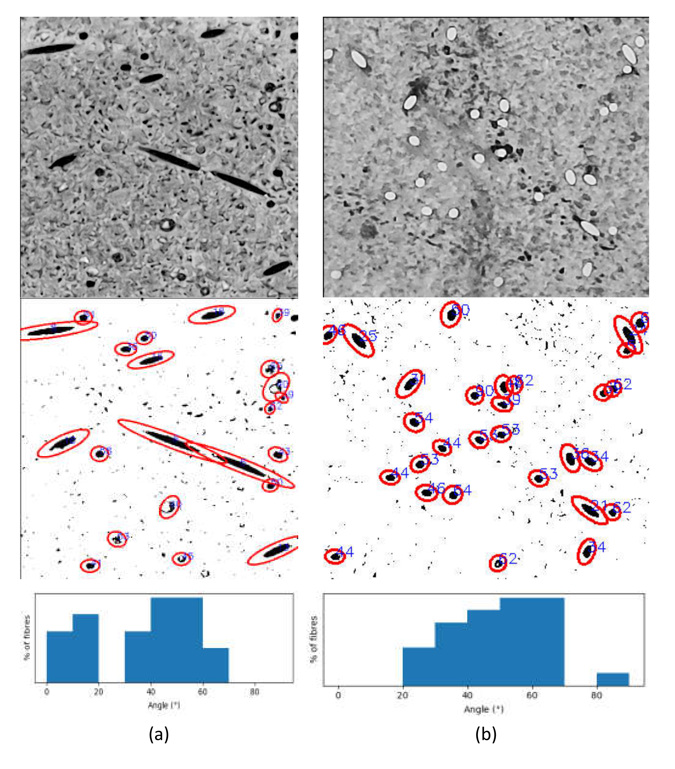
3.1. Fibre Distribution
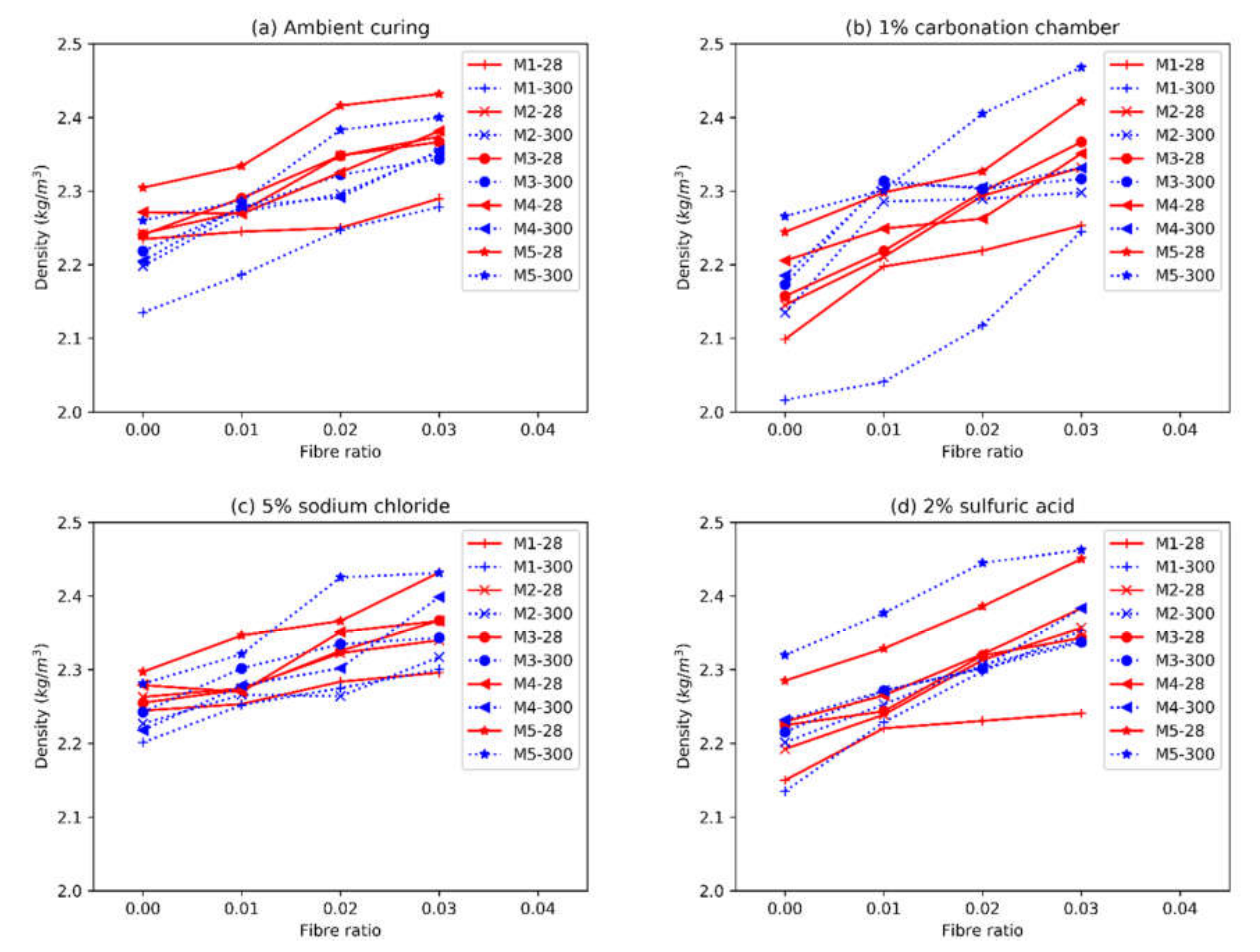
The examples of the distribution of the fibres at 1% and 3% ratios are shown in Figure 3. A relatively uniform dispersion of fibres can be observed in the matrix. The detected fibres are marked by ellipses and the angle of the fibre to the cross-section are shown next to the ellipses and in the histograms. As the angle approached 90°, the error increased due to the small difference between the two axes of the bounding ellipse. Additionally, the mechanical grinding may also alter the shape of the hole, resulting in inaccurate detections. Therefore, the distribution shown was acceptable. At 3%, the fibres were increasingly affected by the neighbouring fibres, therefore the histogram distribution was likely more clustered. The average distance to another fibre was calculated based on the locations of the centres of the fibres. For 1% and 3% replacement ratios, the distances were 4.5 and 3.5 times the diameter of fibre, respectively. Despite having three times the number of fibres, the average distance was not as significantly reduced in specimens with 3% fibre. The fibre content should be optimised to improve efficiency.

3.2. Density

The apparent densities of the specimens of different fibre contents and curing conditions are shown in Figure 4.
Of the five mixes, the OPC control mix always had the greatest density, due to the higher specific gravity of the cement particles. The variations of M5OPC were relatively small across the four curing conditions, even when subjected to sulfuric acid. The expansive delayed ettringite caused spalling and gradually deteriorated the surface of the specimens. However, this did not lead to a significant change in the internal structures, hence the relatively stable density. Similarly, the calcium carbonate and possibly Friedel’s salt formed in the carbonation chamber and salty water, respectively, were both stable and relatively immobile. On the other hand, the densities of the AAFS mixes were more affected by the surrounding environments, due to the more active cations (Na+ compared to Ca2+). The specimens in the carbonation chamber and sulfuric acid baths had significant reductions in densities. The carbonation chamber accelerated the moisture loss due to its lower humidity, and caused the loss of pore fluids through leaching and the formation of efflorescence. The M1 specimens made with a low activator content suffered greatly after 300 days of exposure to this environment, and had the lowest density among all mixes in all curing conditions. The acidic environment in the sulfuric acid bath also greatly accelerated the leaching of pore alkalis, resulting in a higher Na+ detachment rate [17,18] and reduced density. The AAFS specimens half-exposed to the 5% sodium chloride solution had densities similar to the ambient cured specimens. The sodium chloride was less aggressive to the AAFS than CO2 and sulfuric acid. The specimens were also less prone to shrinkage due to the surrounding liquid [12]. Additionally, the higher Na+ content in the environment could reduce the loss of pore alkalis by reducing the concentration gradient between the interior pores and the curing solution [12].
As expected, the additional of steel fibres substantially increased the density of the specimens. In addition, the short fibres used in this study reduced micro-cracking, therefore reducing the deleterious effects of the surrounding environment and the ingress of injurious materials. This was most noticeably observed in specimen M1 cured for 300 days in the carbonation chamber. At 3% fibre content, the density reduction due to the injurious substances was insignificant. In both the carbonated specimens and those cured half-exposed to sodium chlorides, rust in the steel fibres could be observed on the surface of the specimens. However, this did not lead to significant alterations in the integrity and density.

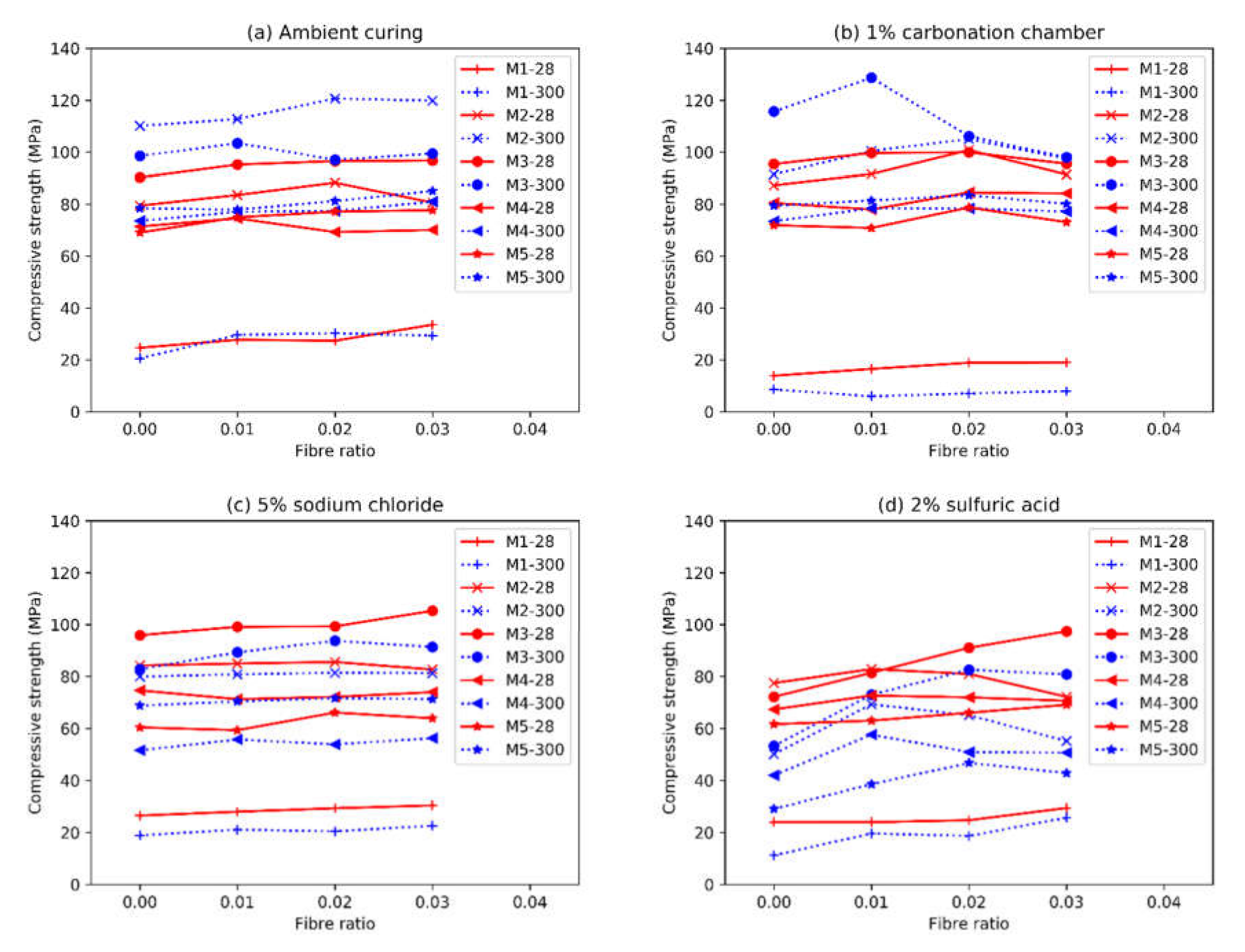
3.3. Compressive Strengths

The compressive strengths of all the specimens at 28 and 300 days are shown in Figure 5.
With ambient curing, the M1 specimens were significantly weaker than specimens from M2-M5OPC due to their low activator content. The mix M3 had the highest compressive strengths at 28 days while M2 specimens were the strongest at 300 days, with compressive strengths exceeding 120 MPa (2%–3% fibre). It was likely that the 6% Na2O in M2 was closer to the optimum activator content for AAFS [20,29]. The excess of activator in M3 could accelerate the early-age strength development but also increase the shrinkage [12,30], hindering future developments in the long-term. M4 had a higher w/b ratio than M2, therefore it had a lower compressive strength at 28 days. The pores resulting from the higher water content were more damaging in the long-term, as the differences between the two mixes increased to 50% at 300 days from 16% at 28 days. The OPC mix only had a slightly better performance than M4 at the given w/b ratio. The development after 28 days was very limited.
The other specific special curing environments mostly had adverse effects on the strength of the AAFS mortars, at varying degrees. The high CO2 content in the carbonation chamber could neutralise the pore alkalinity and cause excessive formation of efflorescence. The lower humidity could also accelerate the micro-cracking in the specimens. The Mix M1 with a low activator content was especially susceptible to carbonation, with noticeable strength reductions at 28 days (40%) and significant reductions (73%) at 300 days compared to their ambient-cured counterparts. The effect of CO2 on the other mixes was limited. This was partly due to the increased resistance to carbonation at high Na2O ratios, and a higher temperature maintained in the carbonation chamber (up to 9 °C difference). It was seen in other studies that, the AAFS composites were sensitive to the ambient temperature [7,12]. A higher temperature could improve the pore refinement and result in denser structures that limit the ingress of deleterious substances. Mix M3 had the highest activator content, and was the least affected by carbonation. At 300 days, M3 had the highest compressive strength of 129 MPa due to the warmer environment. For M5OPC, comparable performances were observed between carbonated and ambient-cured specimens at both 28 and 300 days. All AAFS specimens half-submerged in the sodium chloride solution had various degrees of reduction in strength at 300 days compared to at 28 days due to the long-term leaching. M3, with the highest activator content, was again the least affected by the reduction in alkalinity. All specimens cured in sulfuric acid had lower strengths compared to their ambient counterparts, especially at 300 days. For AAFS mixes, moderate reductions could be seen, due to the rapid loss of pore alkalis. M3 again had the highest strengths while M1 was the weakest. It could be seen that the higher activator content may appear wasteful in ambient conditions, but was crucial for maintaining high levels of performance in aggressive environments. M5OPC had more reductions in sulfuric acid than in other curing conditions due to the formation of the expansive ettringite. It could be seen that AAFS was more suitable in high-sulphate environments.
Overall, the addition of fibres at various ratios did not result in significant changes in the compressive strengths, which was consistent with the findings in previous experimental investigations [31]. The use of fibre could still improve the compressive strength of the composite. However, a large replacement ratio at 3% could sometimes lead to adverse effects. A large fibre content indicated more disruptions in the concrete matrix, hence the reduced strength. However, the addition of short steel fibres could improve the resistance to micro-cracking or chemical attacks. This is observed in specimens cured in 2% sulfuric acid, especially at 300 days. The internal fibres could then be better protected from the acid attack. The performance of the fibres was not significantly altered by chemical processes, including the chloride anions within 300 days. Based on the experimental results, 1%–2% fibre was optimum in balancing the trade-offs among cost, strength improvement and resistance to aggressive conditions. The combination of fibre-reinforcement and a higher activator content can significantly increase the stability of the AAFS, as shown by the accelerated tests in the three of the most common causes of damage, making it more suitable for uses in harsh environments.

3.4. Elastic Modulus

The elastic moduli of all the specimens measured at 28 and 300 days are shown in Figure 6. As seen from this figure, the elastic moduli of the specimens are relatively stable, with only slight improvements over the plain mortar specimens. Despite the much higher elastic modulus of the steel fibres, the interfacial bond between the matrix and fibre was not great enough to transfer a substantial amount of load to the steel fibre. The elastic moduli of the AAFS and OPC specimens are plotted against the square root of their compressive strengths in Figure 7. It can be seen that the OPC specimens generally have greater elastic moduli than the AAFS specimens, despite their lower compressive strengths. The best fit lines of the AAFS and OPC specimens are shown in Equations (1) and (2). The R2 value for AAFS and OPC specimens are 0.85 and 0.20, respectively. The R2 for the OPC specimens was lower due to the smaller number of specimens and their relatively closer values, whereas the prediction for AAFS achieved a high R2 value.
E c A A F S = 3.71 f c
E c O P C = 4.46 f c
The variations of the elastic moduli across the four curing conditions were also relatively small. The most notable exception was the M1 specimens in the carbonation chambers. It could be seen the combination of continued drying, neutralisation of pore alkalis and formation of efflorescence did significant damage to specimens with low activator content. Overall, the elastic moduli of the fibre reinforced AAFS specimens in different environments can still be reasonably predicted with a single formula.

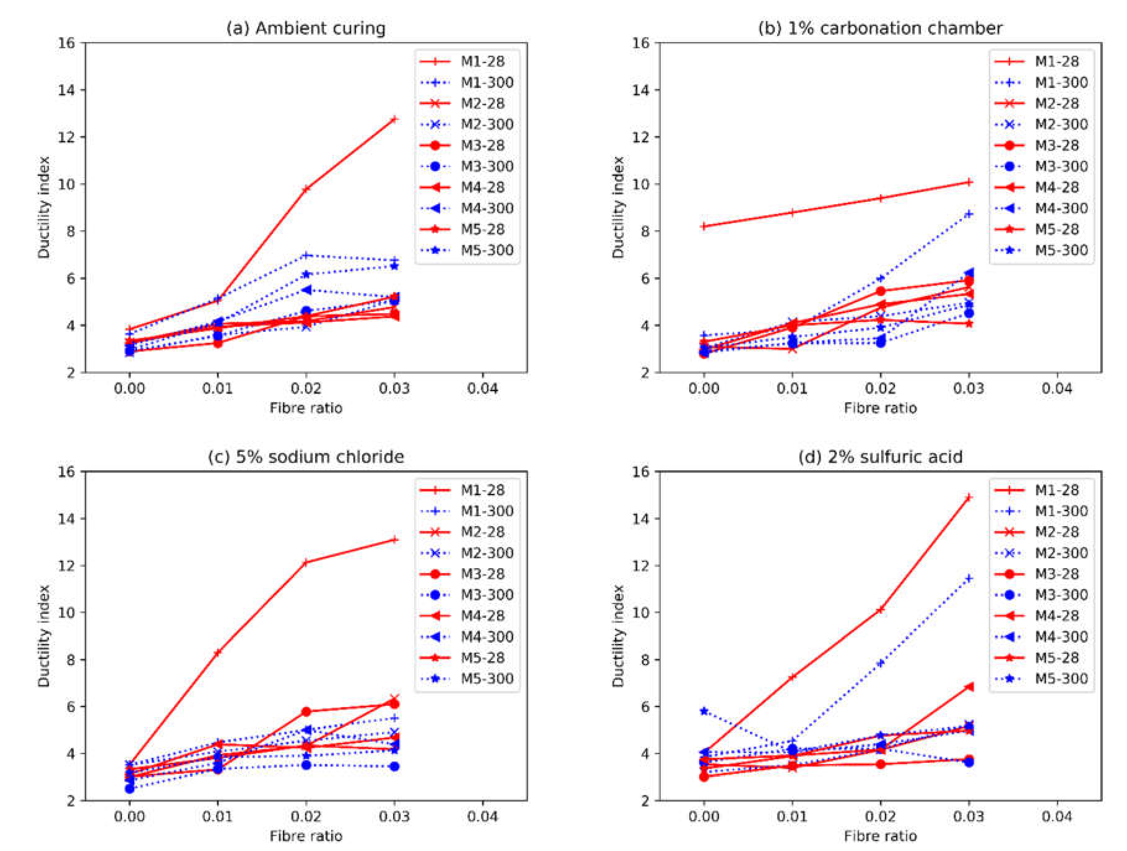
3.5. Ductility Indices
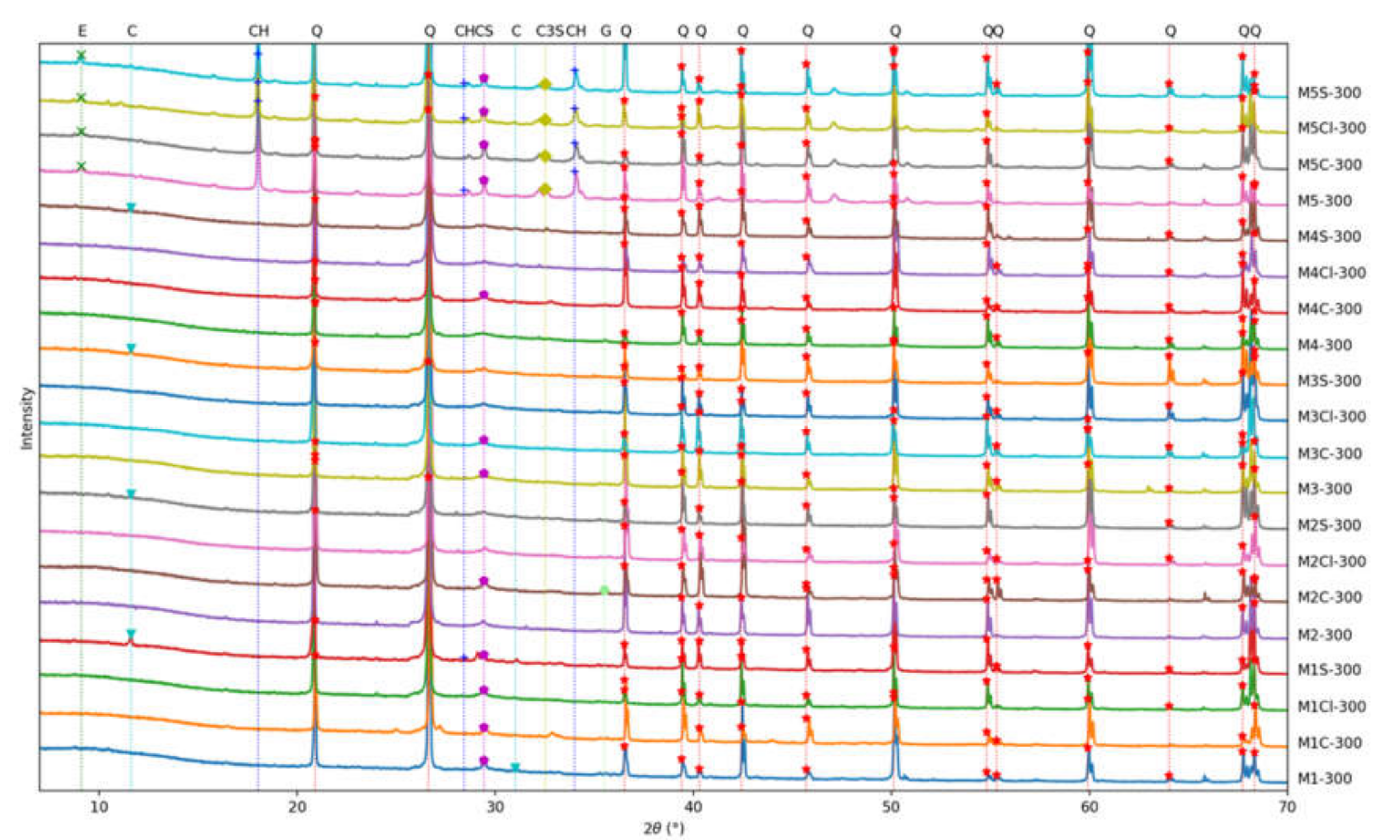
The ductility indices of all the specimens measured at 28 and 300 days are shown in Figure 8. Contrary to the compressive strengths, the DI of M1 is constantly the highest among the five mixes. Specimens with higher compressive strengths tended to be more brittle [32]. Apart from the nature of the mortar matrix, the steel fibres also contributed greatly to the DI of a specimen in compression. The fibres could delay the collapse of the specimen through interlocking and friction. As seen in Figure 9, the average of all the results of a mix in a certain curing environment were plotted against the DI of the specimen with no fibre and tested at 28 days. At 28 days, an average improvement of roughly 30% in DI could be observed by increasing the fibre content by 1%. This number reduced to almost 20% at 300 days, as the mortar continued to harden. The relationships between fibre content and DI in both short- and long- term tests were approximately linear with no diminishing returns, which showed that the addition of fibre could effectively improve the DI in compression. It was likely that even higher DI could be achieved by continuing adding fibres to suit particular requirements.

3.6. XRD Results

The XRD analysis results of the five mixes in four curing environments are shown in Figure 10. The notable peaks (height greater than two times the range of noises) are marked on the figure. In the OPC mix, profound portlandite (CH) and C3S (tricalcium silicate) peaks could be observed as a result of cement. The ettringite peaks at 9° were also only found to exist in the OPC mixes. In mix M5S at 300 days, the ettringite peaks were the most significant compared to specimens in other curing conditions, due to the delayed ettringite formation in a sulphate-rich environment. In AAFS mixes placed in the sulfuric acid tub, the gypsum peaks at 12° were slightly visible. The gypsum was a resultant from the reaction between sulfuric acid and the unreacted CaO in the GGBS. The effect of the formation of gypsum after setting was generally considered to be unfavourable as it could cause expansion and lead to cracking [33]. However, it was also believed that it could fill the pores and hinder further damage [34]. The result showed that the AAFS mixes were more resistant to sulphate attacks than the OPC mix. The damage in such environment was due to other reasons, such as the neutralisation of the pore fluids and leaching of the sodium cations. For AAFS specimens cured in other conditions, no special materials formed in the matrix, as shown in the XRD spectra. Therefore, the AAFS was more stable in the studied environments and could provide protection to the embedded reinforcement and fibres if the rate of leaching could be limited to a satisfactory level.

3.7. SEM Results

As shown from the XRD results, the AAFS specimens were especially stable in CO2- and chloride- rich environments. Therefore, the SEM images of the broken pieces taken near the surfaces of M1S, M3S, and M5S are shown in Figure 11. In M1S, a large amount of gypsum (calcium-sulphate-hydrate) can be seen, while in M3S, the presence of gypsum concentrations can hardly be observed. This was due to the higher activator content, which improved the pore refinement and slowed down the ingress of the acidic solutions. The reaction product in the OPC mix M5S was entirely different. Clusters of the needle-shaped ettringite could be found throughout the matrix.
Figure 12 shows the steel fibres inside the matrix. It can be seen that the hole that the fibre is situated in is noticeably larger than the fibre. Generally, the matrix conformed well to the shape of the fibre. The sand particles distributed around the fibre. On the righthand side of Figure 12a, a larger gap is seen, which could be an air void formed during mixing and enlarged by the grinding and polishing processed used during the preparation of the thin film sample. Figure 12b shows the rust formed on the surface of the fibre inside a sizable void. The rust formed from the reaction between the fibre with the oxygen and water accumulated in the void. As the rust continues to grow, the expansion will eventually create stress concentrations in the matrix. A dense microstructure was required to limit the ingress of water and oxygen into the pores. In Figure 12c, cracks are seen inside the cross-section of the fibre during what was likely a crushing failure in compression. The cracks propagated to the surrounding mortar and caused cracking in the matrix. Despite the relatively smooth surface of the fibres and the low level of bonding between the fibres and matrix, the fibres could be load bearing, which explains the slightly increased compression capacity and elastic modulus.
Figure 13 shows the steel fibres in the CO2-, chloride-, and sulphate- rich environments, respectively. In the carbonation chamber, the elevated levels of CO2 did not have a direct impact on the steel fibres. Instead, the mortar surrounding the fibre was susceptible to carbonation damage. The chloride had a direct impact on the steel fibre and caused corrosion on the surfaces, provided there was abundant oxygen for the oxidation reaction. The rust appears to have a foliated texture (Figure 13b). It was shown that the rust (Fe2O3·nH2O) can be expansive [35], therefore a dense microstructure was required to reduce the corrosion. In the sulfuric acid (Figure 13c), the acid could react with the steel fibre after the coating was damaged during batching and mixing. The resultant FeSO4 could act as a protective layer and reduce the rate of reaction. The FeSO4 layer was soft and poorly adherent [36], therefore it will not result in dangerous expansion. However, this layer was also easily damaged, which may lead to further corrosion. Based on the mechanical test results, the corrosion in the latter two conditions was greatly limited by the protection from the mortars. It was shown that the AAFS was more suitable for protecting the embedded fibres in such aggressive environments, while at the same time the fibres could increase the strength and ductility, and reduce cracking of the mortar.

4. Conclusions

The use of AAFS composites promotes the recycling of industrial wastes and byproducts and reduces the extraction of natural resources. The AAFS is also considered a durable and stable material due to the lack of free lime in the matrix. The effect of high concentrations of CO2, a combination of chloride and air, and sulfuric acid on the performance of steel fibre reinforced AAFS mortars was investigated. These conditions simulated the extreme and long-term exposure to marine environments.
The primary finding is that the stable AAFS could provide protection to the fibres, which were vulnerable to chloride and acid attacks. The incorporation of steel fibres allows for the use of a higher-than-normal activator ratio, which would otherwise lead to significant micro-cracking, and thus improves the resistance of the AAFS to the ingress of the injurious elements.
More specifically:
  • A high activator content above 6% Na2O did not lead to improvements in the compressive strength, but increased the resistance of AAFS mortars to the ingress of deleterious materials, such as CO2 and sulfuric acid. A high activator content can also provide protection for the embedded fibres.
  • The addition of fibre had a low impact on the compressive strength of the mortar specimens. A low fibre content could slightly improve the strength while a large fibre content could lead to disruptions in the matrix and reduce the strength.
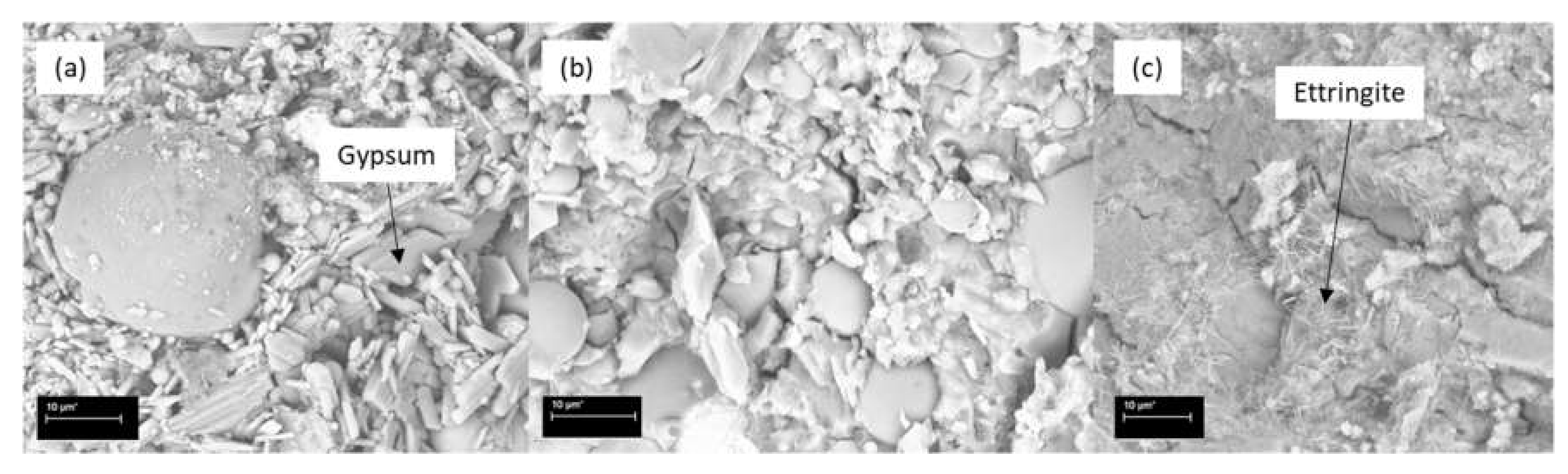
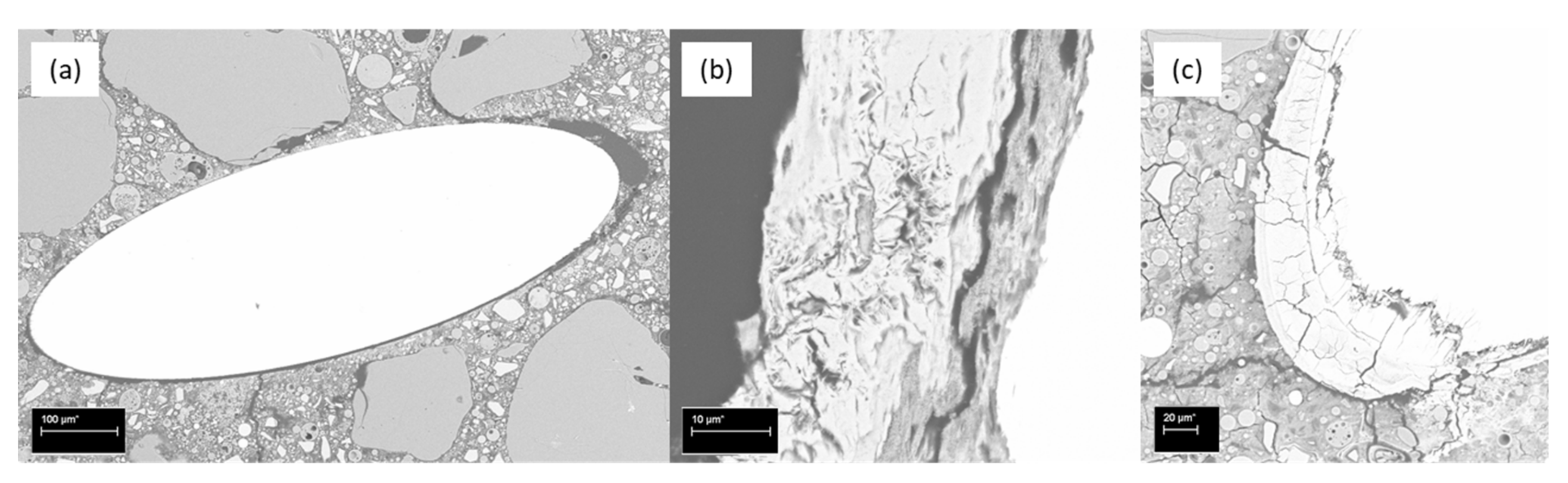
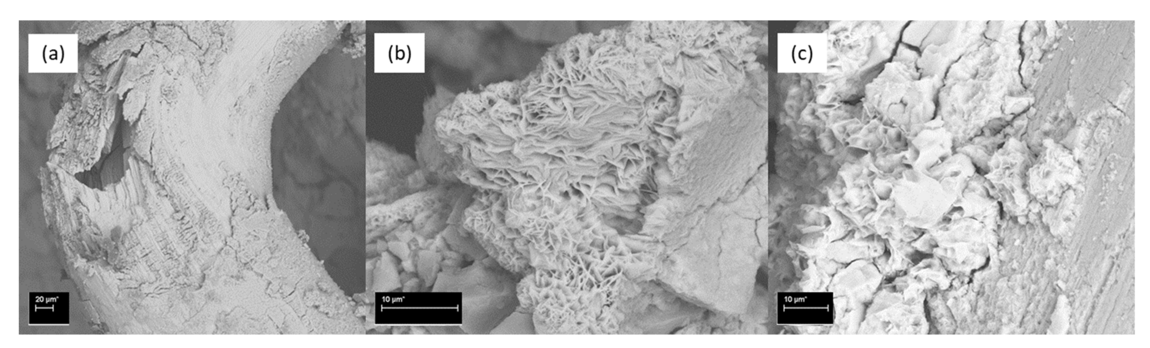
  • The most damaging environment for both the OPC and AAFS was the 2% sulfuric acid. The sulfuric acid caused spalling in the OPC mortar, while the density of the unaffected part remained relatively unchanged. For AAFS mortar, this leached out the pore fluids, and caused the detachment of the sodium cations, causing a reduction in density. The addition of short fibres could limit the development of cracking, thus reducing the negative effects of the aforementioned processes. The ettringite peak in the XRD spectrum of the OPC specimen in sulfuric acid was more profound, indicating that delayed ettringite formation had occurred. In AAFS, small gypsum peaks were identified, with no ettringite formation. The SEM showed that the regions on the fibre exposed to the air voids were prone to rust. Both chloride and acid attacks could significantly impact the performance of the fibres.
  • The elastic moduli of both AAFS and OPC mortars were strongly correlated to the square root of the compressive strength, regardless of the curing condition. AAFS composites had lower elastic moduli than OPC.
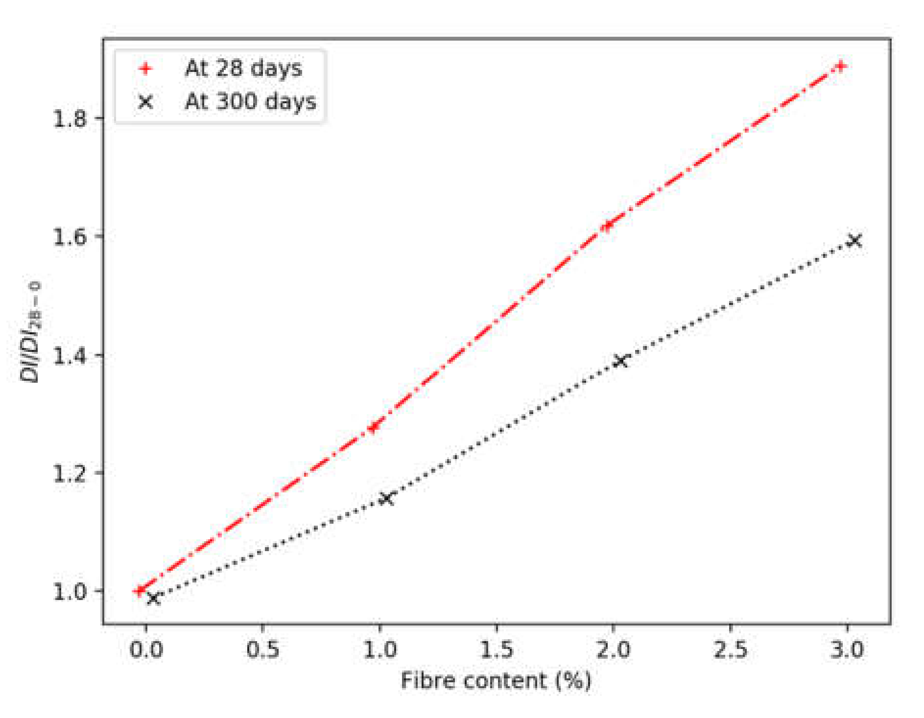
  • The ductility increased linearly with the increase of fibre content, even at a 3% volumetric ratio. At 28 days, each percent increase in fibre content resulted in a 30% increment in ductility. This reduced to about 20% after 300 days of curing, due to the higher mortar strength.
  • The inter-fibre distance was not significantly reduced by tripling the fibre content from 1% by volume to 3%. Based on the results presented in this study, the combination of 1%–2% volumetric ratio of short steel fibres and 9% Na2O in the AAFS was the most suitable combination against the tested extreme environments. The option to use fibre reinforced AAFS to extend the design life of the marine structures could be also explored.

Author Contributions

M.E., A.K. and B.Y. designed the study and experiments. B.Y. organised the funding for the experiment. M.D., M.E. and A.K. performed the experiments. M.D. collected and processed the experimental data. All authors contributed to the data analysis. M.D. and M.E. wrote the paper with input from all the authors. All authors have read and agreed to the published version of the manuscript.

Funding

This research was funded by 111 Project of China (Grant No. B18062) and the Fundamental Research Funds for the Central Universities (No. 2019CDQYTM037) in China.

Acknowledgments

This research was supported by an Australian Government Research Training Program (RTP) Scholarship. The authors acknowledge the facilities, and the scientific and technical assistance of Australian Microscopy & Microanalysis Research Facility at the Centre for Microscopy, Characterisation & Analysis, the University of Western Australia, a facility funded by the university, and state and commonwealth governments. The authors thank the support provided by Coogee Chemicals, Western Australia. Thanks are also given to laboratory technicians Brad Rose and Jim Waters for the help with the many practical aspects of this project.

Conflicts of Interest

The authors declare no conflict of interest.

References

  1. Provis, J.L.; van Deventer, J.S.J. Alkali Activated Materials; Springer: Dordrecht, The Netherlands, 2014; Volume 13. [Google Scholar] [CrossRef]
  2. Chen, C.; Gong, W.; Lutze, W.; Pegg, I.L.; Zhai, J. Kinetics of fly ash leaching in strongly alkaline solutions. J. Mater. Sci. 2011, 46, 590–597. [Google Scholar] [CrossRef]
  3. Mustafa Al Bakria, A.M.; Kamarudin, H.; Bin Hussain, M.; Khairul Nizar, I.; Zarina, Y.; Rafiza, A.R. The effect of curing temperature on physical and chemical properties of geopolymers. Phys. Procedia 2011, 22, 286–291. [Google Scholar] [CrossRef] [Green Version]
  4. Li, X.; Wang, Z.; Jiao, Z. Influence of curing on the strength development of calcium-containing geopolymer mortar. Materials 2013, 6, 5069–5076. [Google Scholar] [CrossRef] [PubMed]
  5. Komnitsas, K.; Yurramendi, L.; Bartzas, G.; Karmali, V.; Petrakis, E. Factors affecting co-valorization of fayalitic and ferronickel slags for the production of alkali activated materials. Sci. Total Environ. 2020, 721. [Google Scholar] [CrossRef] [PubMed]
  6. Jang, J.G.; Lee, N.K.; Lee, H.K. Fresh and hardened properties of alkali-activated fly ash/slag pastes with superplasticizers. Constr. Build. Mater. 2014, 50, 169–176. [Google Scholar] [CrossRef]
  7. Dong, M.; Feng, W.; Elchalakani, M.; Li, G.; Karrech, A.; May, E.F. Development of a high strength geopolymer by novel solar curing. Ceram. Int. 2017, 43, 11233–11243. [Google Scholar] [CrossRef] [Green Version]
  8. Khan, M.Z.N.; Shaikh, F.A.; Hao, Y.; Hao, H. Synthesis of high strength ambient cured geopolymer composite by using low calcium fly ash. Constr. Build. Mater. 2016, 125, 809–820. [Google Scholar] [CrossRef]
  9. Al-Majidi, M.H.; Lampropoulos, A.; Cundy, A.B. Steel fibre reinforced geopolymer concrete (SFRGC) with improved microstructure and enhanced fibre-matrix interfacial properties. Constr. Build. Mater. 2017, 139, 286–307. [Google Scholar] [CrossRef] [Green Version]
  10. Chen, W.; Brouwers, H.J.H. The hydration of slag, part 1: Reaction models for alkali-activated slag. J. Mater. Sci. 2007, 42, 428–443. [Google Scholar] [CrossRef]
  11. Brough, A.R.; Holloway, M.; Sykes, J.; Atkinson, A. Sodium silicate-based alkali-activated slag mortars. Part II. The retarding effect of additions of sodium chloride or malic acid. Cem. Concr. Res. 2000, 30, 1375–1379. [Google Scholar] [CrossRef]
  12. Dong, M.; Elchalakani, M.; Karrech, A. Curing conditions of alkali-activated fly ash and slag mortar. J. Mater. Civ. Eng. 2019. [Google Scholar] [CrossRef]
  13. Olivia, M. Durability Related Properties of Low Calcium Fly Ash Based Geopolymer Concrete; Curtin University of Technology: Bentley, Australia, 2011. [Google Scholar]
  14. Komljenović, M.; Baščarević, Z.; Marjanović, N.; Nikolić, V. External sulfate attack on alkali-activated slag. Constr. Build. Mater. 2013, 49, 31–39. [Google Scholar] [CrossRef]
  15. Allaby, M. A Dictionary of Geology and Earth Sciences, 4th ed.; Oxford University Press: Oxford, UK, 2013. [Google Scholar]
  16. Albitar, M.; Mohamed Ali, M.S.; Visintin, P.; Drechsler, M. Durability evaluation of geopolymer and conventional concretes. Constr. Build. Mater. 2017, 136, 374–385. [Google Scholar] [CrossRef]
  17. Iwahiro, T.; Komatsu, R.; Ikeda, K. Chemical Compositions of Gels Prepared from Sodium Metasilicate and Aluminum Nitrate Solutions. In Proceedings of the International Conferences on Geopolymers 2002—Turn Potential into Profit, Melbourne, Australia, 28–29 October 2002; pp. 1–8. [Google Scholar]
  18. Shayan, A.; Tennakoon, C.; Xu, A. Specification and Use of Geopolymer Concrete in the Manufacture of Structural and Non-Structural Components: Experimental Work; Austroads Ltd.: Sydney, Australia, 2016. [Google Scholar]
  19. Yao, X.; Yang, T.; Zhang, Z. Compressive strength development and shrinkage of alkali-activated fly ash–slag blends associated with efflorescence. Mater. Struct. 2016, 49, 2907–2918. [Google Scholar] [CrossRef]
  20. Dong, M.; Elchalakani, M.; Karrech, A. Development of high strength one-part geopolymer mortar using sodium metasilicate. Constr. Build. Mater. 2020, 236. [Google Scholar] [CrossRef]
  21. Ganesan, N.; Abraham, R.; Deepa Raj, S. Durability characteristics of steel fibre reinforced geopolymer concrete. Constr. Build. Mater. 2015, 93, 471–476. [Google Scholar] [CrossRef]
  22. Rekha, K.; Hazeena, R. Strength and durability of fibre reinforced geopolymer concrete. Int. J. Sci. Eng. Res. 2014, 5, 412–416. [Google Scholar]
  23. Rivera, F.J.M. Strength and Durability of Fly Ash-Based Fiber-Reinforced Geopolymer Concrete in a Simulated Marine Environment; Florida Atlantic University: Boca Raton, FL, USA, 2013. [Google Scholar]
  24. Standards Australia. Supplementary Cementitious Materials Part 1: Fly Ash; AS/NZS 3582.1:2016; Standards Australia: Sydney, Australia, 2016. [Google Scholar]
  25. Wang, S.D.; Scrivener, K.L.; Pratt, P.L. Factors affecting the strength of alkali-activated slag. Cem. Concr. Res. 1994, 24, 1033–1043. [Google Scholar] [CrossRef]
  26. Standards Australia. Methods of Testing Concrete; AS 1012; Standards Australia: Sydney, Australia, 2014; pp. 1–63. [Google Scholar]
  27. Elchalakani, M.; Dong, M.; Karrech, A.; Li, G.; Mohamed Ali, M.S.; Manalo, A. Behaviour and design of air cured GFRP-reinforced geopolymer concrete square columns. Mag. Concr. Res. 2018, 1–63. [Google Scholar] [CrossRef]
  28. OpenCV. OpenCV n.d. Available online: https://opencv.org (accessed on 3 January 2020).
  29. Gao, X.; Yu, Q.L.; Brouwers, H.J.H. Properties of alkali activated slag-fly ash blends with limestone addition. Cem. Concr. Compos. 2015, 59, 119–128. [Google Scholar] [CrossRef] [Green Version]
  30. Melo Neto, A.A.; Cincotto, M.A.; Repette, W. Drying and autogenous shrinkage of pastes and mortars with activated slag cement. Cem. Concr. Res. 2008, 38, 565–574. [Google Scholar] [CrossRef]
  31. Sayyad, A.S.; Patankar, S.V. Effect of Steel Fibres and Low Calcium Fly Ash on Mechanical and Elastic Properties of Geopolymer Concrete Composites. Indian J. Mater. Sci. 2013, 2013. [Google Scholar] [CrossRef]
  32. Warner, R.F.; Rangan, B.B.; Hall, A.S.; Faulkes, K.A. Concrete Structures; Longman: South Melbourne, Australia, 1998. [Google Scholar]
  33. Sturm, P.; Gluth, G.J.G.; Jäger, C.; Brouwers, H.J.H.; Kühne, H.C. Sulfuric acid resistance of one-part alkali-activated mortars. Cem. Concr. Res. 2018, 109, 54–63. [Google Scholar] [CrossRef]
  34. Allahverdi, A.; Škvára, F. Sulfuric acid attack on hardened paste of geopolymer cements part 1. Mechanism of corrosion at relatively high concentrations. Ceram. Silik. 2005, 49, 225–229. [Google Scholar]
  35. Wang, Z.; Zhao, X.-L.; Xian, G.; Wu, G.; Raman, S.R.K.; Al-Saadi, S.; Haque, A. Long-term durability of basalt- and glass-fibre reinforced polymer (BFRP/GFRP) bars in seawater and sea sand concrete environment. Constr. Build. Mater. 2017, 139, 467–489. [Google Scholar] [CrossRef]
  36. Panossian, Z.; De Almeida, N.L.; De Sousa, R.M.F.; Pimenta, G.D.S.; Marques, L.B.S. Corrosion of carbon steel pipes and tanks by concentrated sulfuric acid: A review. Corros. Sci. 2012, 58, 1–11. [Google Scholar] [CrossRef]
Figure 1. Particle size distribution of the binders and sand.
Jmse 08 00278 g001
Figure 2. The straight-end fibres used in this study.
Jmse 08 00278 g002
Figure 3. Distribution of fibres at (a) 1%, and (b) 3%. Note that the numbers denote the angle to the cross-section.
Jmse 08 00278 g003
Figure 4. The apparent densities of the specimens at 28 and 300 days in (a) the ambient curing room, (b) the carbonation chamber, (c) open-air sodium chloride baths, and (d) sulfuric acid baths.
Jmse 08 00278 g004
Figure 5. The compressive strengths of the specimens at 28 and 300 days in (a) ambient curing room, (b) carbonation chamber, (c) open-air sodium chloride baths, and (d) sulfuric acid baths.
Jmse 08 00278 g005
Figure 6. The elastic moduli of the specimens at 28 and 300 days in (a) ambient curing room, (b) carbonation chamber, (c) open-air sodium chloride baths, and (d) sulfuric acid baths.
Jmse 08 00278 g006
Figure 7. The relationship between elastic modulus and the compressive strength (fc). Note that only alkali-activated fly ash and slag (AAFS) specimens were differentiated for clarity.
Jmse 08 00278 g007
Figure 8. The ductility indices of the specimens at 28 and 300 days in (a) ambient curing room, (b) carbonation chamber, (c) open-air sodium chloride baths, and (d) sulfuric acid baths.
Jmse 08 00278 g008
Figure 9. Normalised ductility indices at various fibre contents (DI28-0: DI of the plain mortar specimen at 28 days).
Jmse 08 00278 g009
Figure 10. X-ray diffraction (XRD) patterns of the five mixes in four curing conditions at 300 days. Q: Quartz; CH: Portlandite; E: Ettringite; C: Gypsum; CS: C3S/CaCO3/C-S-H; C3S: C3S; M: Mullite; G: Magnetite.
Jmse 08 00278 g010
Figure 11. The concrete specimens in sulfuric acid, (a) M1S, (b) M3S, and (c) M5S.
Jmse 08 00278 g011
Figure 12. The steel fibres in polished thin films: (a) the interfacial zone between fibre and matrix, (b) the rust formed on the fibre, and (c) a fracture occurred in the fibre.
Jmse 08 00278 g012
Figure 13. The steel fibres in broken pieces, from (a) M3C-F2, (b) M3Cl-F2, and (c) M3S-F2.
Jmse 08 00278 g013
Table 1. Oxide compositions of fly ash, ground granulated blast-furnace slag (GGBS) and ordinary Portland cement (OPC).
MaterialAl2O3CaOFe2O3K2OMgOMnONa2OP2O5SiO2SO3TiO2LOI 1
%%%%%%%%%%%%
Fly ash23.97.07.91.01.30.10.40.555.90.31.30.4
GGBS13.143.20.80.35.50.20.30.031.44.00.60.6
OPC5.365.12.60.41.40.10.40.021.00.00.33.4
1 Loss on ignition.
Table 2. Mix compositions.
MixM1M2M3M4M5OPC
Ms1111-
w/b0.350.350.350.400.35
Na2O%3.00%6.00%9.00%6.00%-
Fly ash (%)14%13%12%13%-
Slag (%)14%13%12%13%-
OPC (%)----30%
Activator (%)5%10%15%10%-
Sand (%)58%59%59%58%59.7%
Free water (%)9%5%2%6%10%
Superplasticiser (%)----0.3%

