Article

Investigating Polymer Fibre Optics for Condition Monitoring of Synthetic Mooring Lines

by
Tessa Gordelier
1,*,
Phillip Rudolph Thies
1,
Giovanni Rinaldi
1 and
Lars Johanning
1,2
1
College of Engineering Mathematics and Physical Sciences, Penryn Campus, University of Exeter, Cornwall TR10 9FE, UK
2
Naval Architecture, Harbin Engineering University, Nantong Main Street 145, Nangang District, Harbin 150001, China
*
Author to whom correspondence should be addressed.
J. Mar. Sci. Eng. 2020, 8(2), 103; https://doi.org/10.3390/jmse8020103
Submission received: 30 December 2019 / Revised: 27 January 2020 / Accepted: 31 January 2020 / Published: 9 February 2020
(This article belongs to the Special Issue Monitoring of Coastal and Offshore Structures)

Abstract

:
Synthetic mooring lines are becoming a popular alternative to conventional chain mooring systems. For marine renewable energy devices, they have been considered as an enabling technology for this nascent sector, given their reduced costs and ease of deployment. However, the extreme operating environment has led to an increased interest in the ‘in-situ’ condition monitoring of these mooring lines. This paper considers the use of polymer fibre optic technology and the optical time domain reflectometry (OTDR) technique for the condition monitoring of synthetic mooring lines. To establish the operating envelope of the fibres, Polymethylmethacrylate (PMMA) polymer optical fibres are mechanically tested. Additionally, an OTDR is used to monitor fibres whilst under elongation using a tensile test machine, and the sensitivity of the system in monitoring strain is established. At the lowest strain rate, the average proportional limit and yield points of the fibres are found at 1.16% strain and 5.41% strain, respectively. Fatigue exposure of fibres up to 1.25% strain identifies no measurable effect on fibres’ proportional limit or yield point. The occurrence of significant creep is identified for fibres strained beyond 1.5%. The OTDR system is able to identify strains at and above 4%. The study identifies important criteria that should be considered in the integration of polymer optical fibres for mooring applications. Limitations are discussed and suggestions for progressing this technology are provided.

Graphical Abstract

1. Introduction

1.1. Synthetic Rope Mooring Systems

For the bourgeoning marine renewable energy sector, driving down costs and improving reliability are key to establishing a successful market. Replacing expensive chain mooring systems with synthetic mooring lines has been identified as one such shift that could enable these changes [1]. In comparison to conventional mooring chains, they are cheaper, lighter, introduce more compliance into the system and are easier to deploy [2].
Whilst the use of synthetic mooring systems is also being promoted in the oil and gas sector, the requirements for marine renewable energy devices (MREs) are notably different. Predominantly, the difference lies in the motion required for MREs to generate energy without creating excessive mooring loads, as described by [3]. Compliance can be introduced into the system via mooring system architecture or by increasing the compliance of the individual mooring elements. Polyester ropes with breaking strains in excess of 12% [1] have been used for offshore platforms for approximately 20 years [2], and work to promote nylon ropes, with breaking strains exceeding 20% [1], is ongoing [4]. However, the existing non-destructive testing (NDT) methods employed for wire ropes or chain moorings [5] cannot be utilised with fibre ropes and, given the challenging and highly dynamic environment of many MRE installations, this has led to an increased interest in novel ‘in-situ’ condition monitoring approaches for mooring ropes. Some early pioneers of condition monitoring in ropes, [6], set out key requirements that such a condition monitoring system should attain. These include the capability to measure strain up to 10% at a 0.1% resolution and the ability to be integrated into a rope over 300 m long. A review of potential methods investigated for this monitoring application is detailed in [7] and includes magnetic techniques, electrical conductive methods, computed tomography, thermography, acoustic emission monitoring and fibre optics—the focus of the work presented here.

1.2. Condition Monitoring Using Optical Fibres

Optical fibres have been used for some time in the health monitoring of quasi-static structures such as bridges, buildings and dams [8]. Due to the minimal movement of these structures, silica fibre (also known as glass fibre), has been appropriate for these applications. Whilst silica fibre has been too fragile for more dynamic applications, such as MRE moorings, advances in polymer optical fibre technology are opening up these potential markets. The benefits of polymer optical fibres (POFs) include improved fracture resistance and durability [9,10]; higher operational strain range in comparison to silica fibre, which is limited to 1% [11]; a lower Young’s Modulus, with PMMA 2.5–3.3 GPa in comparison to 72 GPa for silica; and low cost [12]. They have also been shown to have higher sensitivity to the strain measurement in large strain applications (14% higher sensitivity than a comparable silica optical fibre [13]). The major drawback of POFs is their increased attenuation in comparison to silica fibre; this has limited the application distance. Improvements in manufacturing technology are continuously reducing the attenuation of POFs but it is still significantly below that of silica fibre. Novel polymer materials such as perfluorocarbon-based fibres have achieved very low attenuation, allowing signals to travel beyond 500 m [6], a significant improvement compared to conventional PMMA POFs, which are limited to about 100 m [11], but still a long way from the distances achieved with silica fibre of over 10 km [14].
Given the improved mechanical properties achieved with POFs, several research projects have investigated the use of these fibres for condition monitoring in higher strain applications, including [13,14,15,16], and even within mooring ropes [6]. These studies have established the use of the optical time domain reflectometry (OTDR) technique to detect a strained section of the POF through a change in the backscatter of the optical signal. Whist these studies have evidenced the potential to measure strain, combining that information with the mechanical properties of the polymer fibre and the operational requirements of a mooring rope is crucial to developing a successful condition monitoring system, and provides the focus of the work reported here.

1.3. Paper Outline

This paper seeks to assess the appropriateness of off-the-shelf PMMA for use with the OTDR technique in the condition-monitoring of synthetic fibre ropes in the operating envelope envisaged for MRE applications. Initially, the mechanical properties of the PMMA fibre are investigated, including the proportional limit, yield point, creep and fatigue response. The OTDR technique is then utilised to measure strain in the fibre. The results from these two investigations are compared to review the potential of a PMMA OTDR strain-monitoring system for MRE mooring systems.

2. Materials and Methods

To utilise the POFs in a strain monitoring application, the first step of this work established the mechanical operating envelope of the fibres; the method for this is detailed in Section 2.1. The second step was to ascertain the capability of the OTDR strain measurement instrumentation; the method for this is detailed in Section 2.2. The polymer optical fibre under investigation in all these studies is a multi-mode, 1 mm poly methyl methacrylate fibre (PMMA), manufactured by Mitsubishi. The properties of the fibre supplied by the manufacturer are detailed in Table 1.

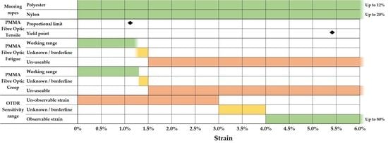
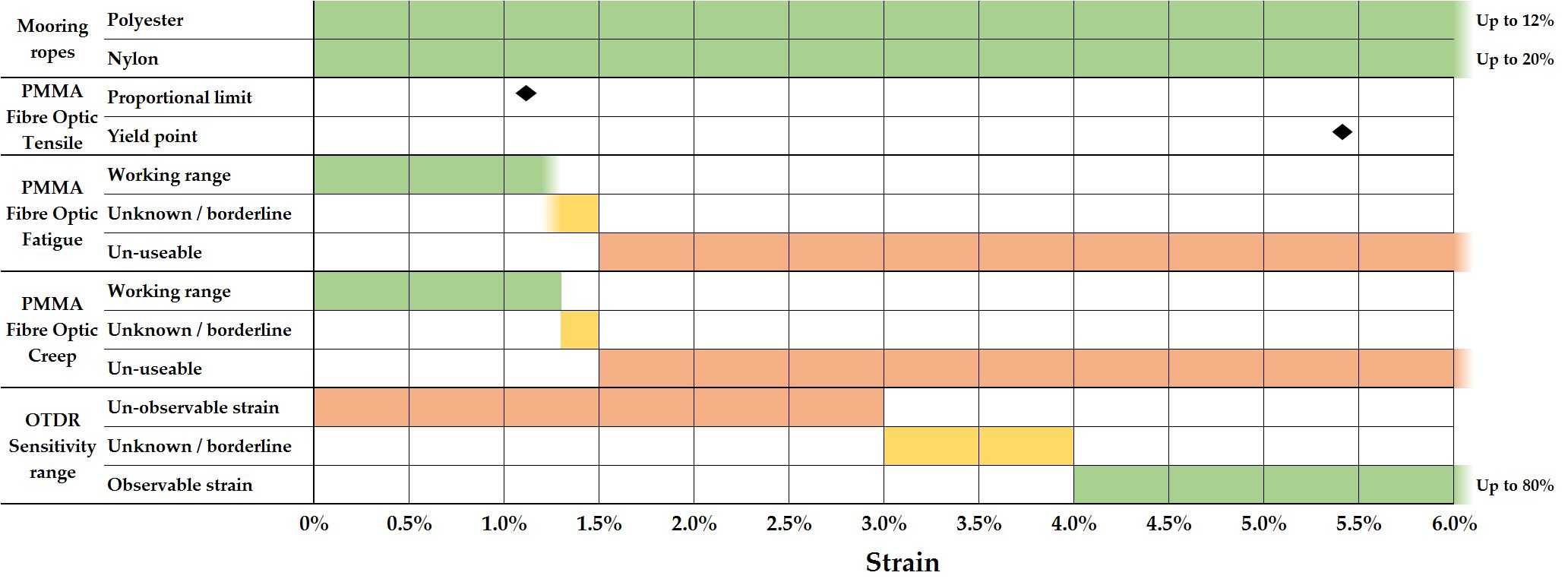
2.1. Establishing the Mechanical Operating Envelope

A typical stress-strain graph for POFs is provided by [17] and summarised in Figure 1.
The first step of this work was to identify the proportional limit and yield point for the fibres under investigation. Once these were established, creep testing and fatigue testing were conducted to understand the usable range of these fibres. Although general consensus seems to be that the fibres behave elastically up to the yield point (as suggested in [17] and shown in Figure 1), it was important to confirm this experimentally for the specific PMMA fibres under investigation.

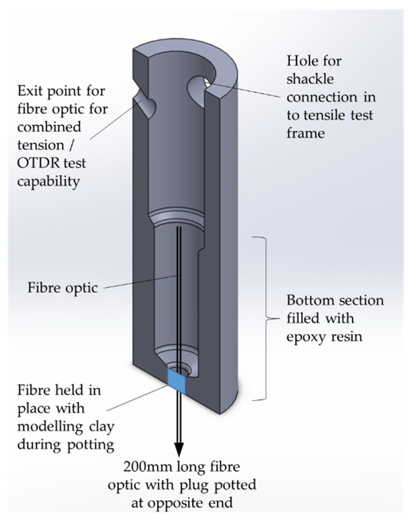
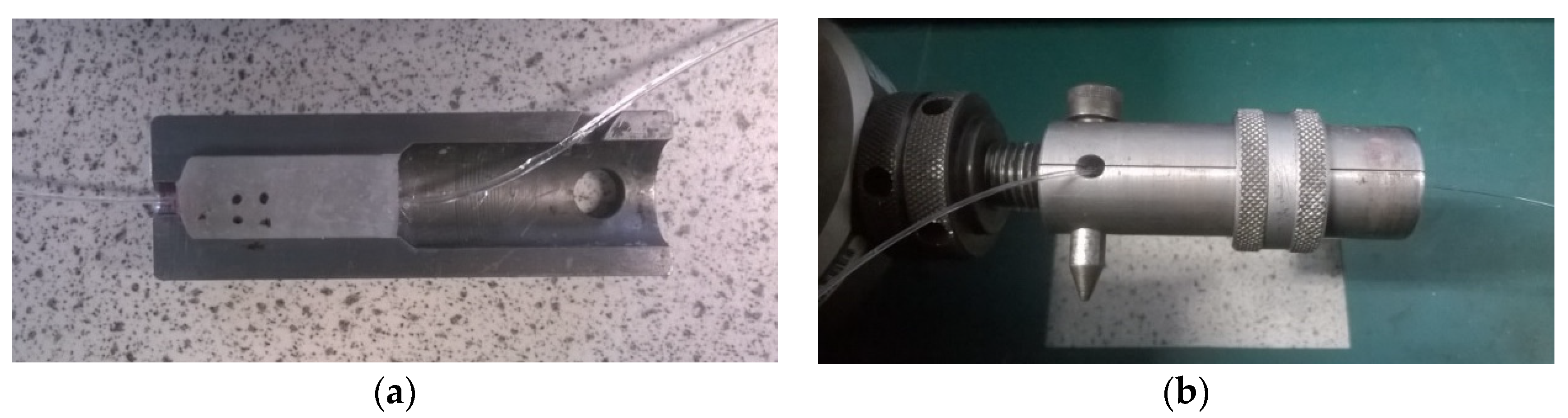
2.1.1. Test Configuration

Bare PMMA fibres were used and, to avoid any crushing of the fibres in the test set up, a collet was designed that allowed the fibres to be ‘potted’ in an epoxy resin; this is detailed in Figure 2. Mold release was used during the potting process and, once cured, the epoxy plugs were released from the mold. Two pairs of collets were then used to secure the fibres in the tensile test machine using small dee shackles. A Lloyd EZ20 tensile test machine was utilised for the testing and was set to record the load, extension, stress and strain at a 10 Hz sampling frequency. A target gauge length of 200 mm for each sample was specified and for each test parameter, a minimum of three successful test runs were performed.

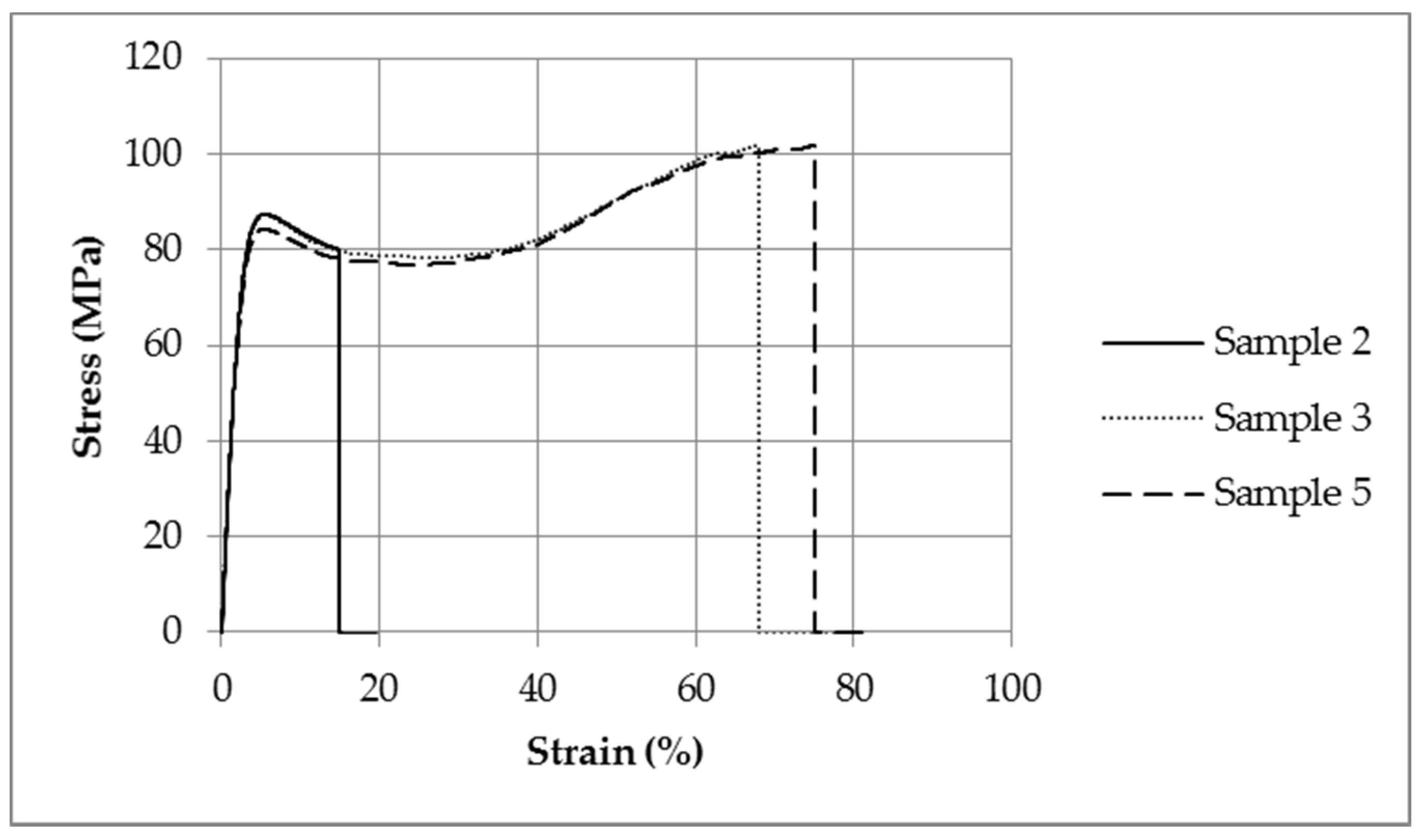
2.1.2. Tension Testing

Initially, three strain rates were investigated with a 1 mm fibre diameter to select the most appropriate one to complete the full suite of tests. A range of strain rates have been investigated by others, ranging 0.005–3.05 strain/min [18,19]. For this work, strain rates representative of the potential strains in a WEC mooring system were specified. Based on data from the South West Mooring Test Facility (SWMTF) [20] typical strain rates of 0.25–2.5 strain/min were investigated.
For each experiment, the proportional limit and yield point for the fibre is defined as follows:
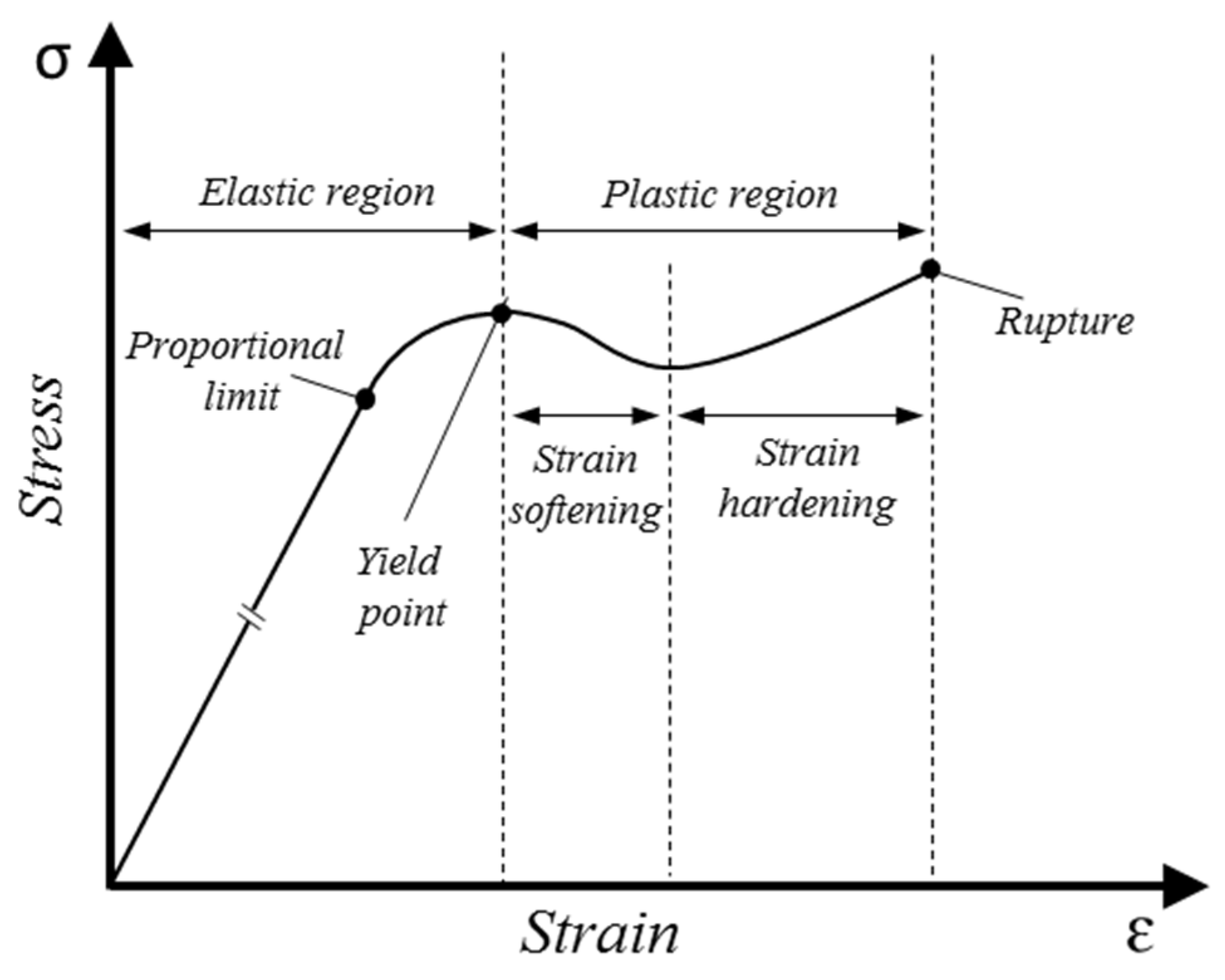
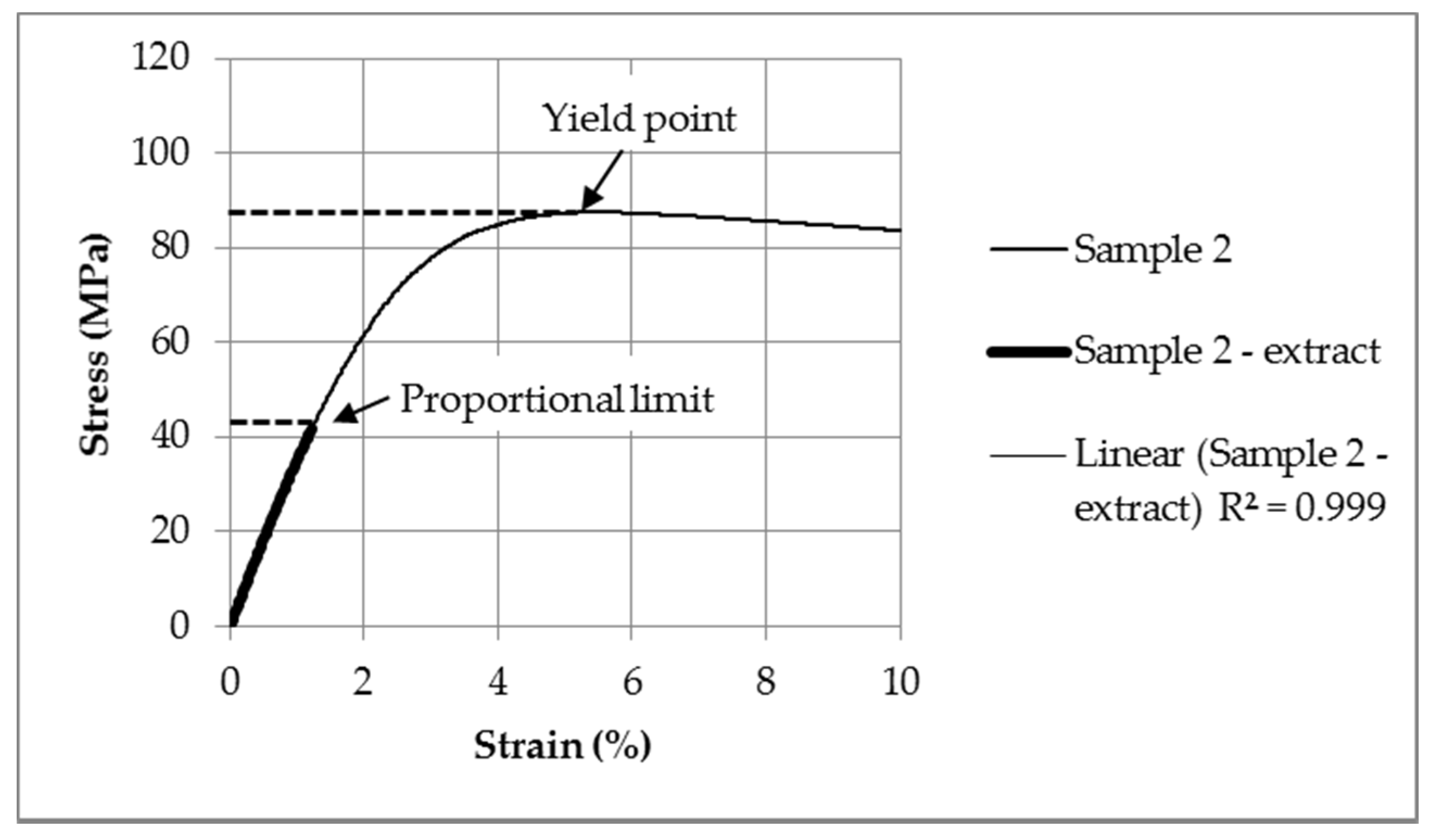
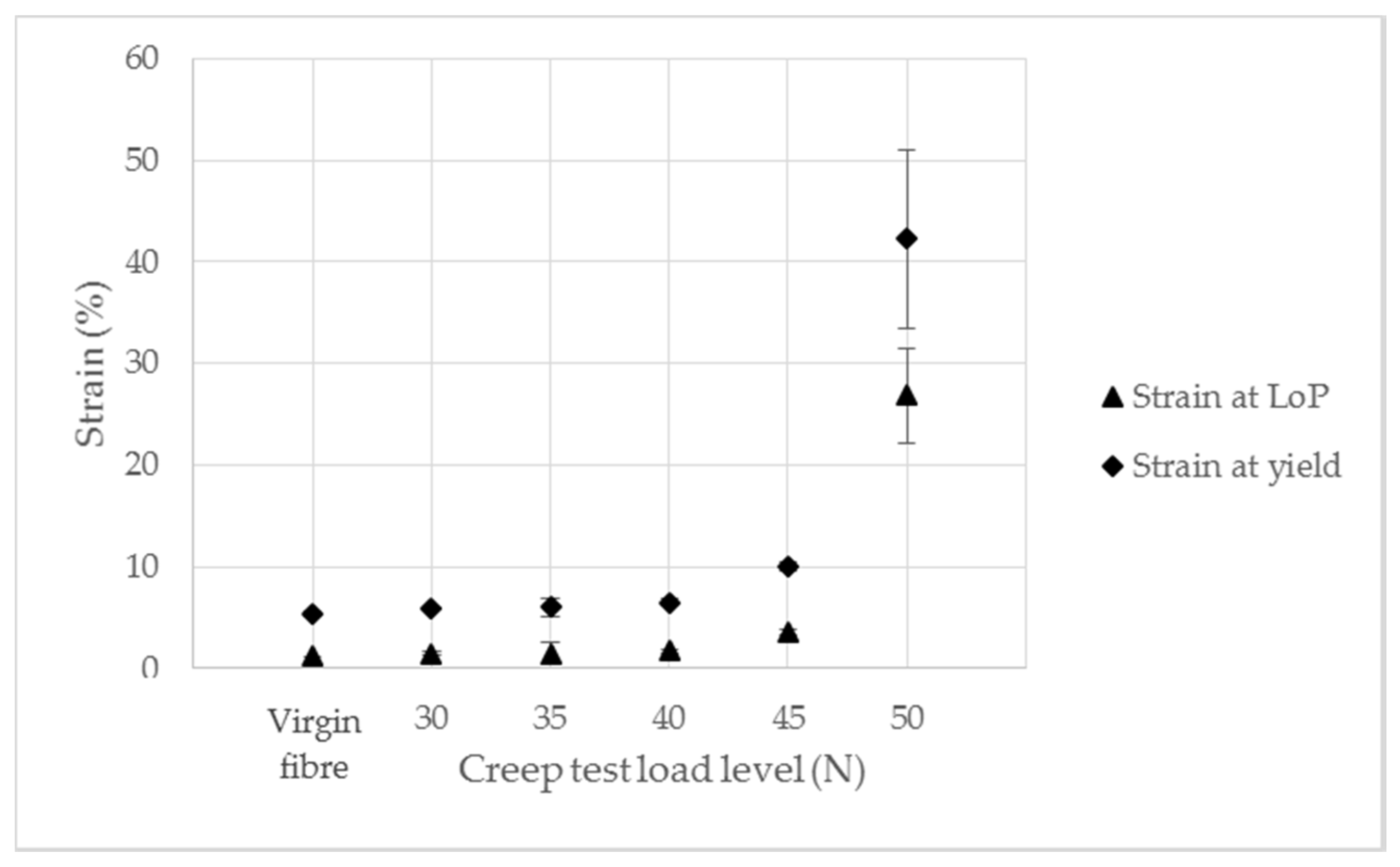
  • Proportional limit: Established by conducting a least squares regression to calculate the coefficient of determination (R2). An R2 value of 0.999 is required to consider the data ‘linear’. Once R2 value drops below 0.999, the data is no longer considered linear;
  • Yield point: The point at which peak stress is observed before strain softening commences.

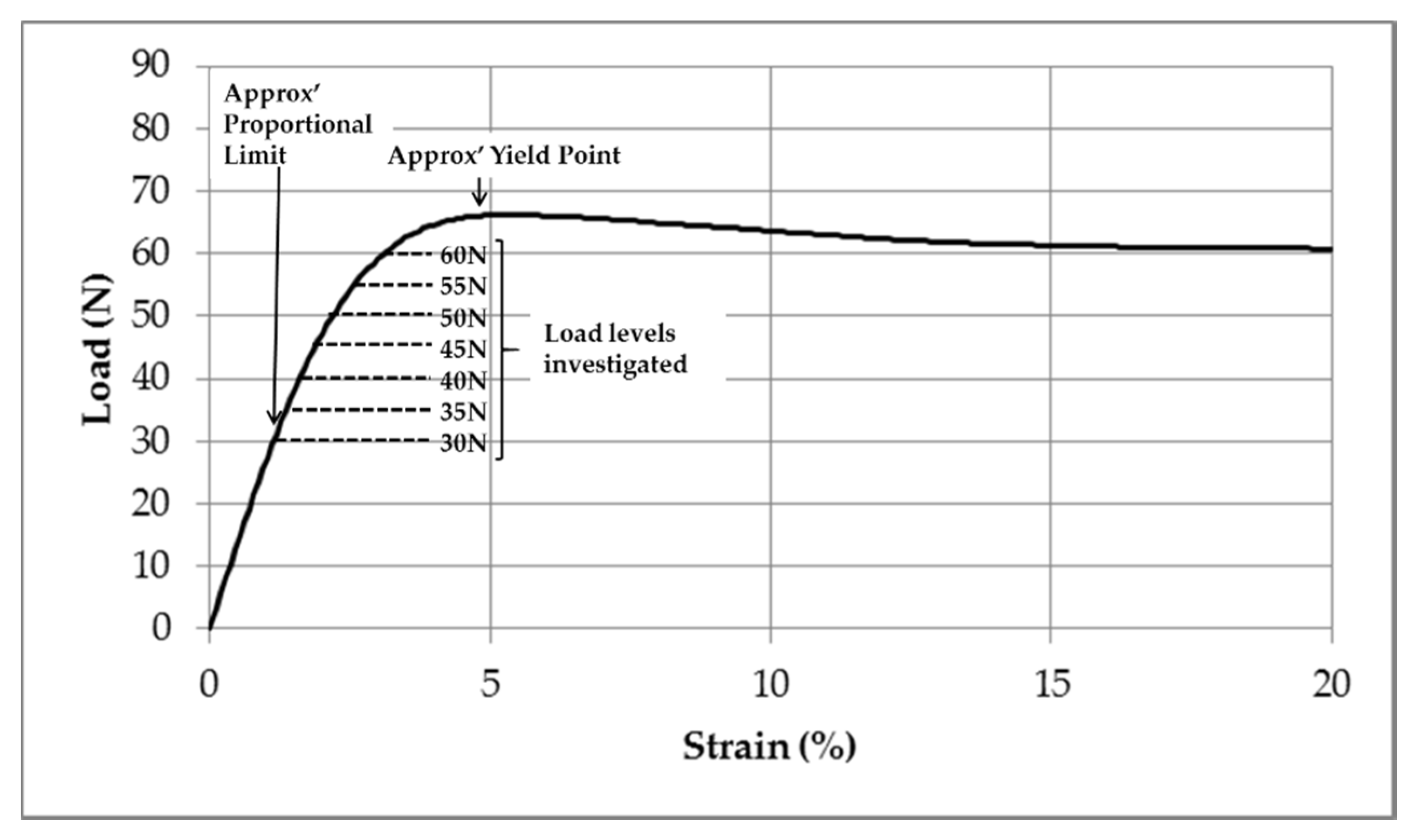
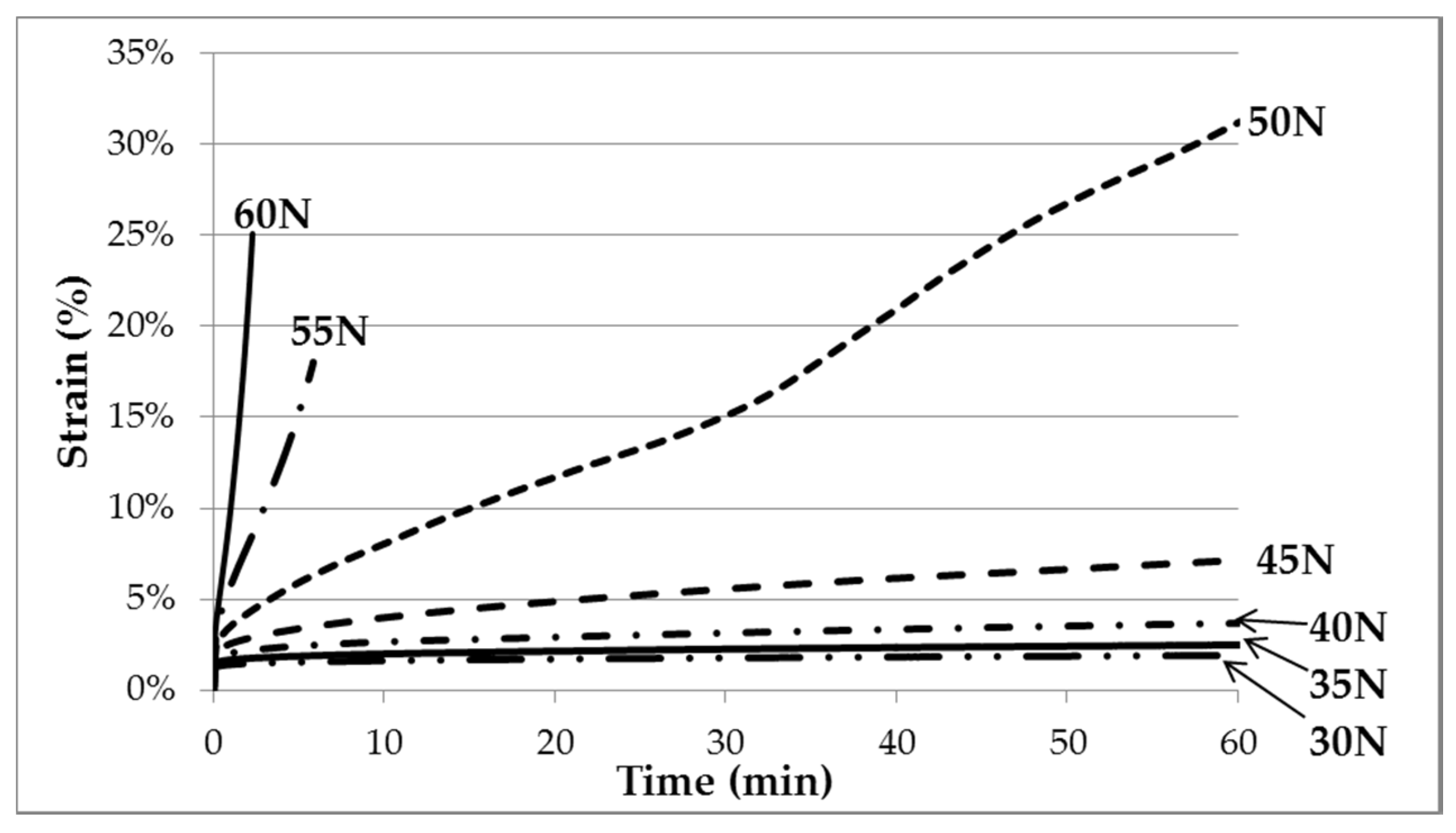
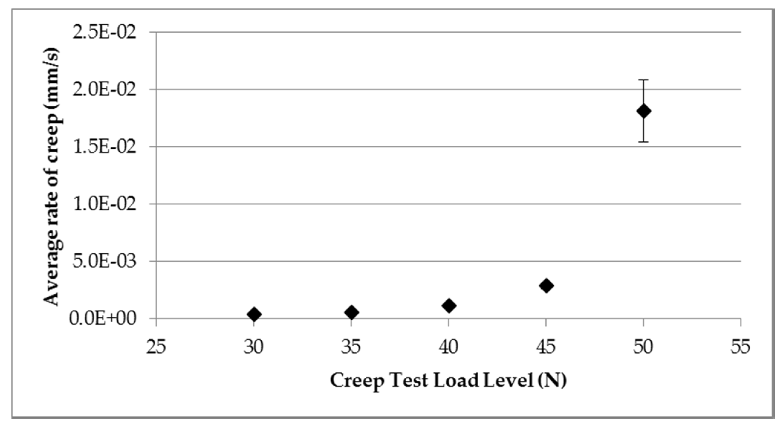
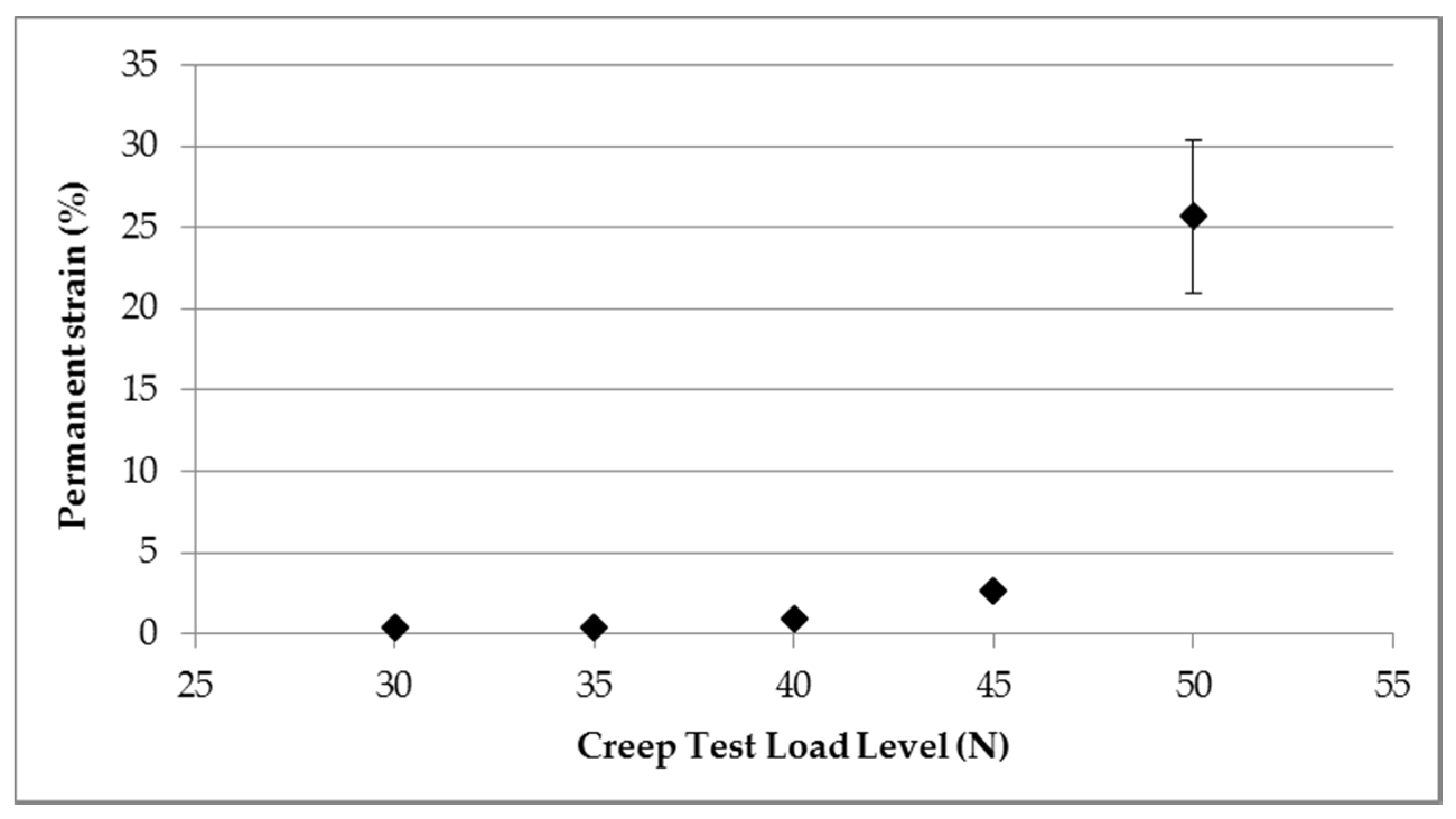
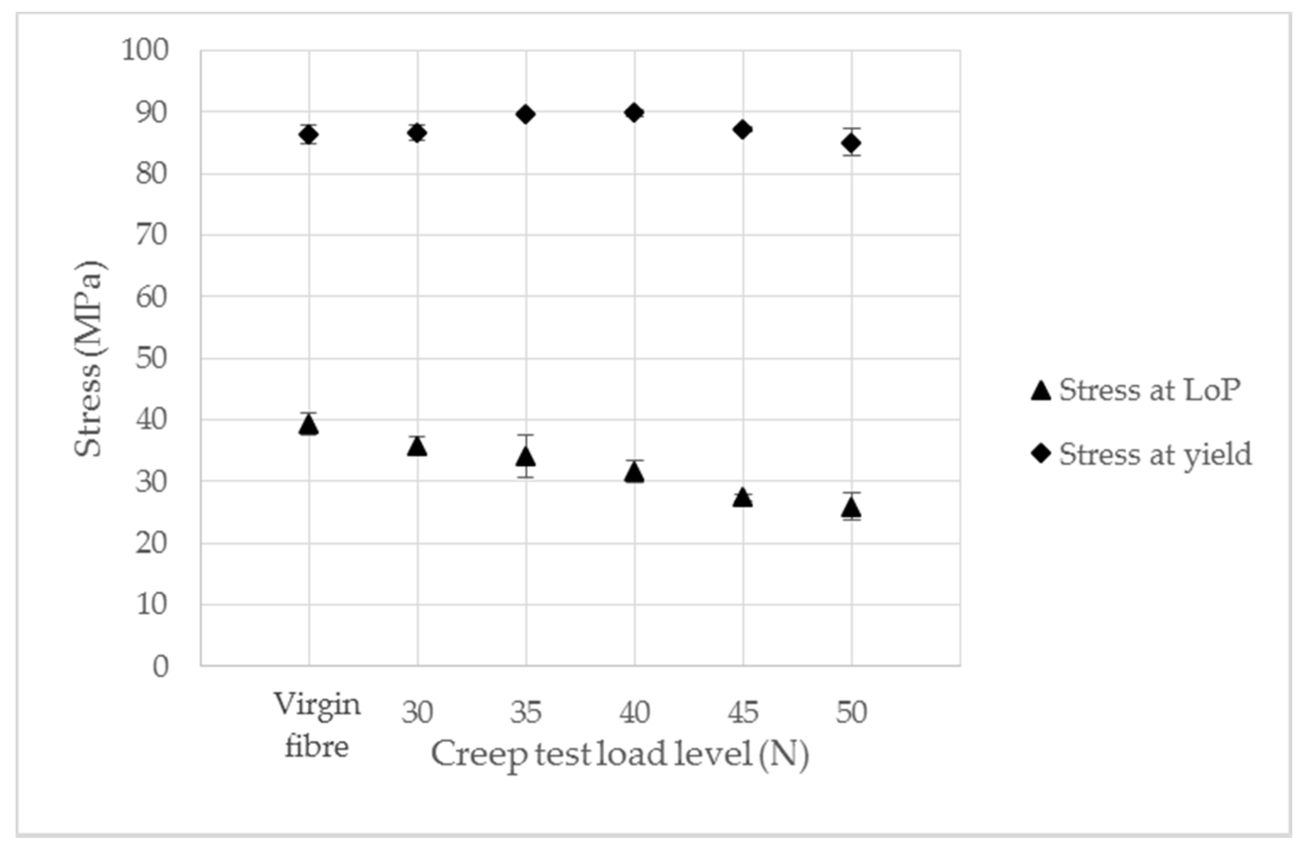
2.1.3. Creep Testing

Any functional condition-monitoring system will be required to hold a given strain over a period of time without deteriorating in functionality. Given the significant difference in strain observed between the proportional limit and yield point in the POFs, understanding the strain limit before significant creep occurs is important for a functional monitoring system. This series tests investigated the creep at a range of strains, from proportional limit up to the yield point.
The Lloyd EZ20 tensile test machine was load-driven at a strain rate of 0.25/min to a specified load and held at this load for 1 hour. Measurements of the sample were taken before and after the creep test to record any permanent deformation. If the sample survived the creep test, it was then subjected to a tensile test to failure. The tensile test to failure started from the same extension and load datum as the creep test. The proportional limit and yield point for the post-creep samples subject to tensile tests were calculated for comparison with the virgin samples. At each load level identified, a minimum of three tests were conducted.

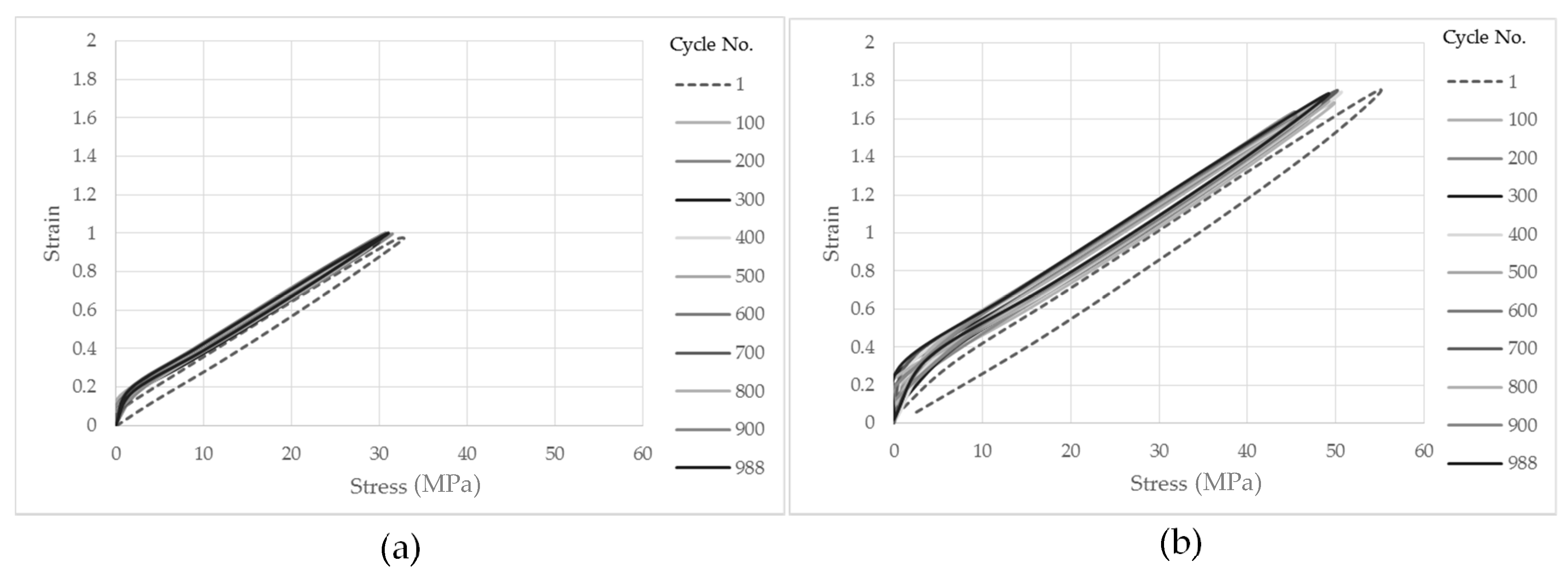
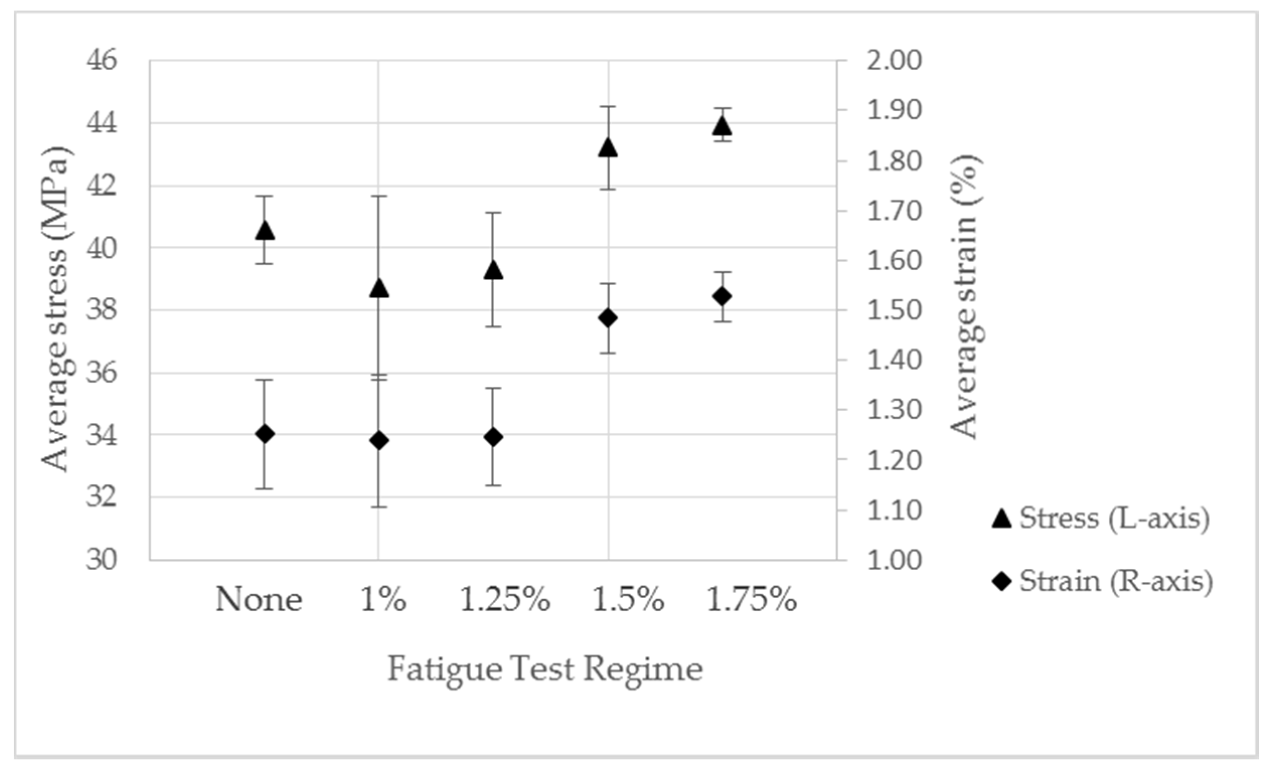
2.1.4. Fatigue Testing

To achieve the successful condition monitoring of mooring lines, the optical fibres were subjected to repeated extension cycles with the movement of the floating body. The fatigue response of the fibres should therefore be investigated at the anticipated working extensions. Given the results of the tensile and creep testing, a fatigue testing regime of 1000 cycles at extensions of 1%, 1.25%, 1.5% and 1.75% strain was conducted as a preliminary investigation into the effect of fatigue-loading on the polymer fibres. The Lloyd EZ20 tensile test machine was driven in displacement mode at a rate of 50 mm/min (corresponding to a strain of 0.25/min), with the exact strain for each test calculated from the gauge length of each sample (gauge length target value of 200 mm). Three samples were tested at each strain level specified.
Following the fatigue cycles, the fibres were subjected to tensile tests to failure, as outlined above.

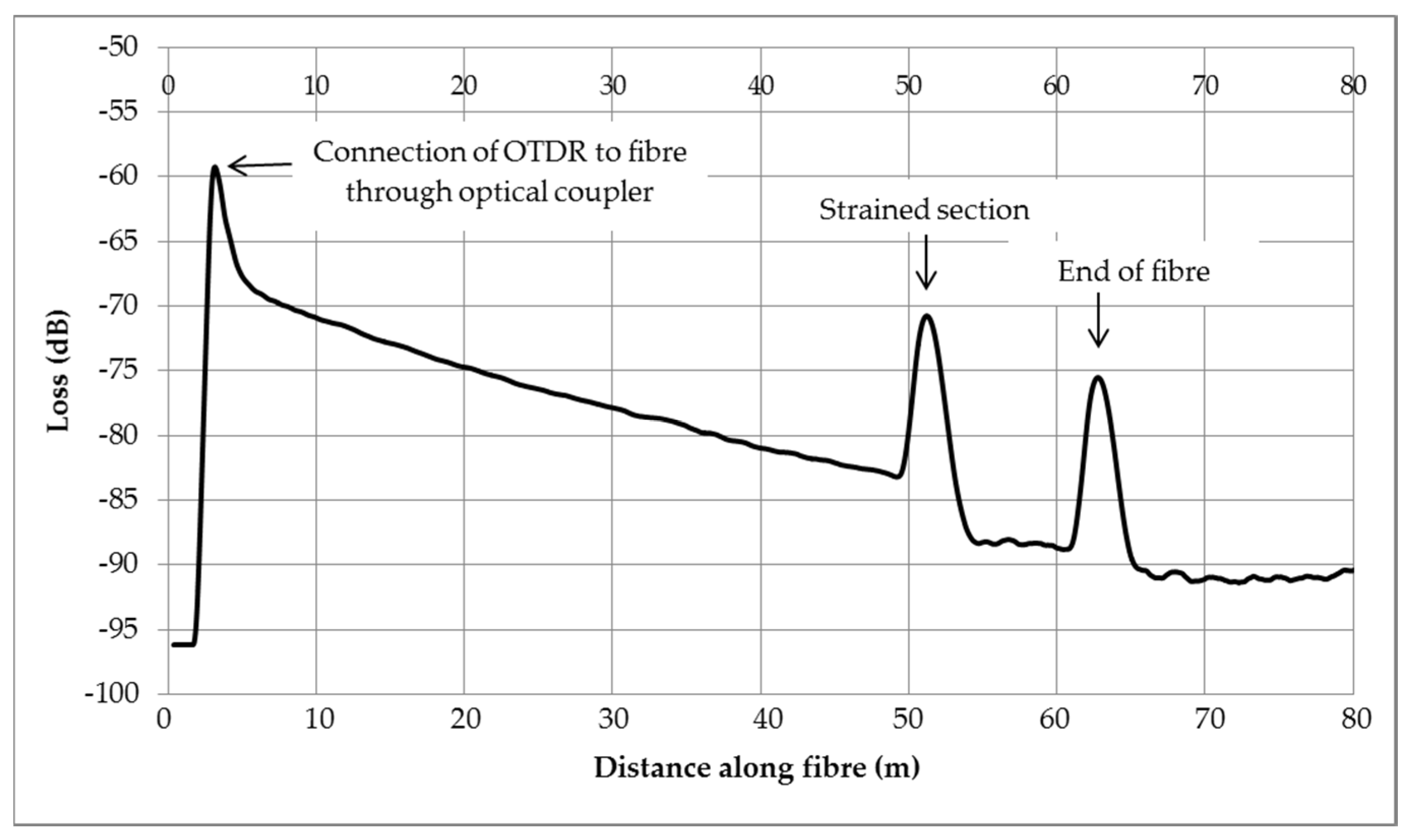
2.2. Optical Time Domain Reflectometer Investigation

Optical time domain reflectometers (or OTDRs) operate by transmitting a laser down the optical fibre as a short optical pulse [14]. As the light travels down the fibre, Rayleigh scattering of the light causes a continuous backscattering reflection [21]. Some of this reflected signal travels back down the fibre optic to the OTDR and is recorded as a function of time, providing a record of the attenuation along the fibre. Different ‘events’ along the fibre, such as a connection face, crack, bend or end of the fibre, will create measurable changes in the reflected signal [22]. Knowing the speed of travel of the light pulse, the OTDR calculates the distance along the fibre of a specific event using the following Equation (1) [22]
D i s t a n c e =   m e a s u r e d   t i m e   ×   s p e e d   o f   l i g h t   i n   v a c u u m r e f r a c t i v e   i n d e x   o f   f i b r e
As previously discussed, the OTDR technique has been trialled by others with POFs fibres to monitor the strain exposure of a fibre [11,14,16,23,24]. Strained sections of fibre increase the backscatter in the signal, and the location of the strain can be identified as discussed above.
To establish the limits of the strain measurement in the PMMA fibre under investigation here, a series of trials were established.

Test Configuration

The signal measured by an OTDR is sensitive to the end effects of a fibre and is also inaccurate in the first 10 m of fibre length. For this test, approximately 60 m of the PMMA fibre was utilised to avoid these issues; the strain testing was conducted 49 m from the OTDR connection point. As described before, the collets were used to form plugs of epoxy resin and also for connection into the tensile test machine. For this testing, to facilitate connection into the OTDR, a plug was formed at either end of a 200 mm gauge length at approximately 49 m along the fibre. The collet was designed to ensure the minimum bend radius of the POF was respected as it exited the collet. The formed plug and connection into the tensile test machine are detailed in Figure 3.
The 60 m fibre under test was connected to the OTDR via an optical coupler. Matching gel was used on the face of the paired fibres to ensure a good connection and to minimise any Fresnel Reflection. This is a loss in the signal, which can occur when light travelling down a fibre optic encounters a material of different density (such as the air gap between two connecting fibres). Applying a matching gel minimises the loss at the connection, which can be up to 4% [25]. As the fibre was un-jacketed, a blackout cloth was placed over all the equipment to ensure no light could penetrate the fibre. A series of sensitivity tests revealed the importance of ensuring a complete blackout of light for recording consistent results.
A Hounsfield H20K-W tensile test machine was used, and the 200 mm gauge length was extended in increments, as specified in Table 2, up to 160 mm. At each displacement step, the load reading was noted and an OTDR scan of the fibre was performed. The OTDR returned a datapoint at 10 mm intervals and the noise was removed from the signal using a ‘movingmean’ function and taking the moving average of 100 data points.

3. Results

3.1. Establishing the Operating Envelope

3.1.1. Proportional Limit and Yield Point

PMMA samples were tested to failure and results analysed, as outlined in Method Section 2.1.2. Figure 4 details a typical stress–strain plot observed for three identical test routines, whilst Figure 5 demonstrates the identification of the limit of proportionality, utilising a least squares regression analysis.
Average yield and proportional limits were calculated for each strain rate and are detailed in Table 3.
To evaluate the impact of strain rate on strain result at proportional limit and yield point, and to demonstrate the spread in the results, Figure 6 has been included. The error bars in this figure represent the sample standard deviation and demonstrate that, whilst there is some spread in the yield point of the samples, the proportional limit is very repeatable between samples. At the lower three strain rates tested, the strain rate does not appear to significantly affect the proportional limit or yield point of the samples. At the highest strain rate of 2.5/min, the strain at proportional limit is slightly elevated, but the strain at yield point is within the range of the results at lower strain rates. Statistical methods could be used to investigate whether the data spread is due to stochastic reasons or caused by a specific trend. However, given that, in a practical application, the strain rate will vary between the rates tested, to ensure a precautionary approach, the lowest strain rate will be used going forward, as this resulted in the lowest average strain at the proportional limit and yield point.

3.1.2. Creep Investigations

The tensile tests above were used to identify appropriate load levels at which to conduct the creep investigations. Figure 7 highlights the load levels, specified in relation to the approximate proportional limit and yield point of the fibres.
A higher load level of 65 N was initially trialled; however, the sample immediately extended over 50% in just 90 seconds and failed. This load was clearly too high so a reduced load of 60 N was specified for the highest load level. A typical strain plot for the tested loads is detailed in Figure 8. The samples held at 60 N and 55 N failed early on in the test, however, the lower loads (30 N–50 N) were maintained for the full hour, although some with significant creep. For those fibres that survived the full creep test, the average rate of creep for the test is detailed in Figure 9, and the permanent strain measured following the removal of the load after the 1 hour test is detailed in Figure 10.
Following the creep tests, any fibres that survived were then subjected to a tensile test to failure to observe any impact the prolonged period of load may have on the stress and strain at the proportional limit and yield point. To quantify any lasting effect of the creep tests on the mechanical properties of the surviving POF fibres, Figure 11 details the impact of the creep test load level on the strain at the proportional limit and the strain at the yield point and compares this to virgin fibre. Figure 12 details the impact of the creep test load level on the stress at proportional limit and the stress at the yield point; again this is compared to virgin fibre.

3.1.3. Fatigue Investigations

All the POF samples survived the 1000 fatigue cycle testing regime at strains of 1%, 1.25%, 1.5% and 1.75%. To observe any change in fibre properties throughout the fatigue cycling, an analysis of the stress–strain plot at evolving cycle numbers was conducted. No significant change was observed at any of the strain levels. Figure 13a,b details examples of this analysis for the 1% and 1.75% strain fatigue testing, respectively. For both plots, it is easy to distinguish Cycle 1 but the remaining cycles are very repetitive, which demonstrates limited change in the properties of the fibre throughout the test. The change observed between Cycle 1 and the other cycles is due to the Mullins Effect [26], which is observed when a polymer is first exposed to a tension or compression load and is characterised by the permanent softening of the stress–strain curve.
Following the fatigue tests, the samples were strained to failure in a simple tension test. The proportional limit and yield point of each fibre was then calculated and compared to virgin fibres to observe any permanent change in the samples. The results of these tests are shown in Figure 14 (proportional limit) and Figure 15 (yield point). These results demonstrate that the 1% and 1.25% strain fatigue testing had no measurable effect on the proportional limit, but the 1.5% and 1.75% strain fatigue testing marginally increased the stress at the proportional limit by 7% and 8% respectively, and significantly increased the strain at the proportional limit by 19% and 22% respectively, demonstrating permanent damage to the fibre.
Regarding any observed changes in the yield point of the fibres, although there is some variation, there is no evidence of a clear trend observed following the fatigue tests.

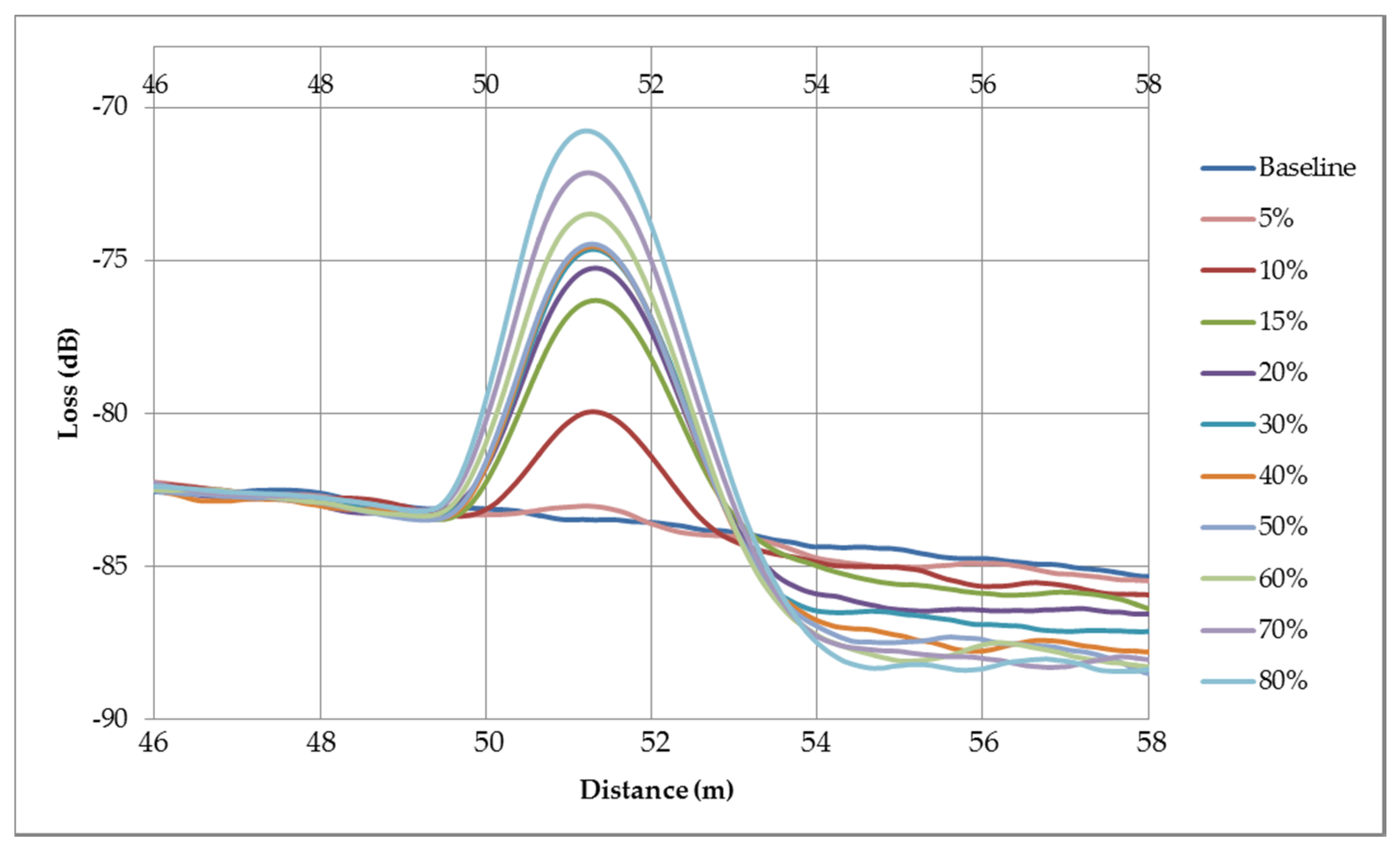
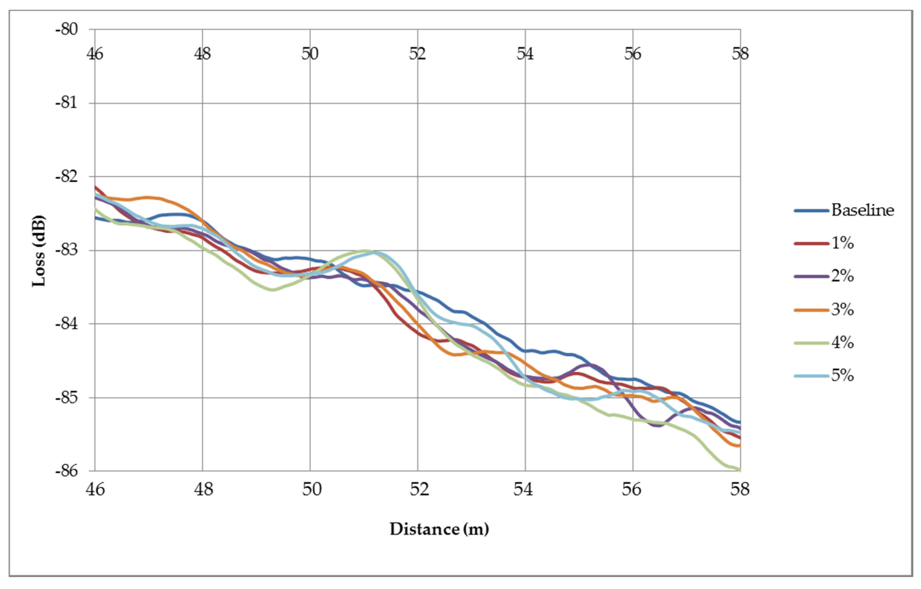
3.2. Optical Time Domain Reflectometer Results
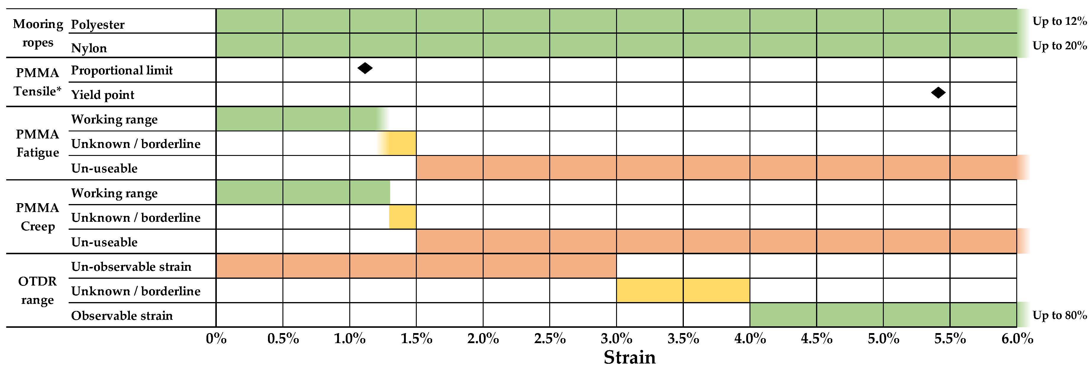
The full suite of OTDR measurements were taken and analysed. Figure 16 details the full OTDR signal when the gauge length was strained at the maximum strain of 80%. Key features of the signal trace have been highlighted for information.
In order to investigate the impact of increasing strain on the measured signal, a range of different strain values, varying from 5% to 80%, at regular intervals of 5%, are plotted in Figure 17. An interval of 5% was selected, in order to identify each strain level in the data. However, whilst strain levels from 5%–20% are readily identifiable, there is considerable overlap in the range of 30–50% strain, before the signals separate out again from 60–80% strain. Following the peak in signal at the fibre section under strain, there is also an evident drop in the measured loss following the strained section. The higher the applied strain, the larger the drop in loss measured.
It is interesting to observe the clear change in OTDR signal from these high strain values, however, considering the observed mechanical properties of the PMMA fibre, the fibre has been extended beyond its proportional limit at these strains. In order to further investigate the measured signal within this region (<5%), a detailed review of the signal at lower strains is therefore provided in Figure 18, with a reduced interval of 1%.
Reviewing Figure 18, the section of fibre between 50–52 m, strained at 4% and 5%, can be marginally identified from the noise in the signal, but strains lower than this are unidentifiable from the general noise.
The data used to generate all the graphs presented in the results section has been included as supplementary data alongside this publication. See the Supplementary Materials section at the end of the paper.

4. Discussion

This work initially established the mechanical operating envelope of the 1 mm PMMA fibres. The average yield point and proportional limits of the fibres were identified at a range of strain rates representing potential operational requirements. The lowest strain rate of 0.25 strain/min resulted in the lowest strains at these points and, in agreement with [19], the lowest stresses. The lower strain rate was therefore used for subsequent tests to represent the most conservative values for an operating system. In relation to the manufacturer properties detailed in Table 1, the average force at 5% strain from these tests was 67.8 N, representing good agreement with the manufacturer’s data, which states 65 N. At the lowest strain rate, the average proportional limit of the fibres was 1.16%, which is less than a quarter of the average strain at the yield point (5.41%). Despite much of the existing literature on polymer fibres only referencing to the yield point [9,16,19], the significant difference observed here between the proportional limit and yield point warranted further investigation. A series of creep and fatigue tests were conducted in the range of these values.
Creep tests at all load levels investigated demonstrated a certain amount of creep and permanent deformation but, crucially, they demonstrated that, at loads well below the yield point, the PMMA fibre exhibits significant creep and would be un-usable. This work suggests that 35 N or 40 N could be an appropriate maximum load limit (corresponding to a maximum strain limit of 1.3% and 1.56%, respectively, at the lowest strain rate discussed). At 40 N, the average rate of creep is 0.0714 mm/min and the average permanent extension is just under 1% (0.92%). If the maximum load was further limited to 35 N, the corresponding average rate of creep is 0.0362 mm/min, with an average permanent extension less than 0.5% strain (0.438%). This viscoelastic nature of the PMMA fibres is also highlighted by [12,27] as a potential issue for any long-term strain-sensing application.
Fatigue testing of 1000 cycles at strains ranging from 1 % to 1.75% strain was also conducted. During the fatigue testing, at all strain levels, no significant change in the stress–strain behaviour of the fibres was observed (despite the level of strain going beyond the maximum strain limit, identified by the creep tests above). This suggests that longer term exposure to strain is more damaging to the fibres than the short strain cycles conducted in fatigue testing at 0.25 strain/min. Following the fatigue tests, tensile failure tests were conducted on the exposed fibres to establish whether there was any permanent damage. No measurable difference was found on the fibres fatigued at 1% and 1.25% strain, however, the fibres fatigued at 1.5% and 1.75% demonstrated, on average, a 19% and 22% reduction in the strain at proportional limits, respectively. This suggests that some permanent damage has occurred and, as such, it is recommended that fatigue cycling of the fibres should be limited to a maximum of 1.25% strain. Further fatigue investigations should be conducted between 1.25% and 1.5% strain to refine this estimate.
Following the identification of the mechanical envelope of the PMMA fibre, investigations utilising the OTDR clearly demonstrated the principle of using this technology to identify strain in the polymer fibres. A clear peak in backscatter signal could be identified for strains exceeding 4%. At strains lower than this, it is difficult to identify a change in signal from the general noise. As a continuous condition monitoring system would have to use an automated system to identify any signal peak (such as a photon counting method, as proposed by [14]), it is unlikely that any such automation could identify anything below 4% strain. Indeed, it may be the permanent deformation of the PMMA fibre itself that leads to the observed change in backscatter. The physical permanent change in the material may alter the reflective properties at the strained point in the fibre, and thereby create the observed peak.
The results from this study are summarised in graphical form in Figure 19, which also includes the working range of two typical synthetic mooring ropes for comparison. The graphic demonstrates that the PMMA fibres cannot be used beyond approximately 1.3% strain, however, the OTDR measurement is not able to identify any strain below 4%. This results in an incompatible system for long term monitoring, whereby, at the point at which the PMMA fibre can identify any strain, it will have suffered permanent damage. The system could be used as an ‘alarm system’ identifying a threshold breech, but it could not be used for continuous condition monitoring.
To overcome this system incompatibility, either the POF material properties should be improved to increase the strain before permanent deformation occurs, or the measurement technique should be improved to identify strains occurring at lower levels. The following will discuss the research in these areas.
The manufacturing process of PMMA fibres has a significant effect on fibre properties. Research by [19,28] and [9] demonstrate that the drawing temperature, the annealing process and the concentration of doping dye DR1 can all significantly affect the mechanical strength and strain of the fibres. Jiang et al. [19] suggest that fabrication parameters effect the molecular alignment of the fibres, and these should therefore be optimised in order to produce a material with the desired strength and extension properties. The pre-tensioning of polymer fibres is also shown to improve mechanical properties, including tensile strength, modulus and toughness [28]. Given the fairly niche application of POFs for monitoring strain in fibre ropes, this research highlights the need to work closely with a fibre manufacturer in order to optimise the fibres for this specific purpose.
This paper has focused on PMMA, however, other polymer fibres are being developed that may have advantageous properties. Smith and Williams [6] consider the use of a perfluorocarbon-based polymer optical fibre which has the advantage of very low attenuation (0.03 dB/m at 850 nm, in comparison to 2 dB/m at 850 nm for PMMA). This low attenuation means that signals can travel beyond 500 m, significantly further than in PMMA, which is limited to about 100 m [11]. One fibre could therefore be used to monitor long distances and potentially multiple mooring limbs. Additionally, the properties of the fibre allow an improved spatial resolution of up to 10 cm. The perfluorocarbon fibre is shown to work as a strain measurement technique using the OTDR approach to identify correlations with strains as low as 0.5% [6]. Further work on this type of fibre is conducted by [11], who use the OTDR technique to identify strains from 1.8%–100% in a poly (perfluorobutenylvinylether) fibre, known commercially as Cytop. Additionally, [11] also develop an Optical Frequency Domain Reflectometry (OFDR) approach to measure the fibre backscatter and suggest this approach has a higher resolution, and is quicker and more cost effective than the standard OTDR technique. Despite the potential benefits of this fibre, limited information is available on the mechanical properties, though [6] note that it appears to be approaching plastic deformation at around 7% strain. Further work is certainly required to establish the working mechanical envelope of this fibre.
In addition to altering the POF materials, alternative measurement techniques should also be considered. A development of the OTDR technique is discussed by [6], who propose inserting ‘physical interferences’ at known points along a POF. The OTDR scan can then be used to measure the distance between these physical interferences and any subsequent change in this distance. The paper suggests this technique has been used to measure strains of 0.1% over a 33 foot gauge length [6].
Another measurement technique that works along these principles is considered by [9], who investigate the potential of Fibre Braggs Gratings (FBG). A thorough explanation of this technique is provided by [7] and, whilst being well established for silica fibre, it is an emerging technology with POFs [29,30,31,32]. A Bragg Grating structure is inscribed into the optical fibre using ultraviolet light [10], a broadband light source is launched down the fibre, and an optical spectrum analyser is used to monitor the reflection spectra and identify the fibre Bragg wavelength peak. Upon straining, this wavelength peak shifts, and the shift in wavelength is directly correlated to strain. Webb [9] uses this technique to identify correlations from 0.05% strain upwards.
Although the approaches discussed above allow lower strains to be identified in POFs, the operating strains of synthetic fibre ropes are still significantly higher than the useable operating envelope of PMMA fibres. To avoid excessive strains in the fibre optic altogether, [33] investigated three different prototypes during the development of the final proposed transducer design for use with glass fibres as part of the OSCAR project (Optical Scanning Apparatus for Ropes). The transducer system works by inserting a glass optical fibre into a loose, gel-filled tube which is installed around an inner core at a high helix angle. There is a threshold transducer elongation, up to which there is no elongation of the optical fibre (whilst the optical fibre shifts from the centre of each gel-filled tube to the wall). Once the fibre reaches the wall of the tube, further transducer elongation imparts elongation to the optical fibre. The helix angle and tube diameter determine the level of gearing, from transducer to optical fibre, and it would be possible to have a range of loose tube diameters to offer different inspection ranges. An even simpler design is proposed by [34], who wrap a fibre in a helix around the core within a rope structure, achieving a strain of 0.4% for a rope strain of 2.5% (a 1:6.25 ratio). Although these types of design overcome the issue of over-straining the PMMA fibres considered here, the fact that no signal can be observed by the OTDR until the PMMA fibre is permanently damaged remains, and so an alternative monitoring system would be required, as discussed above. O’Hear [33] adopts the Brillouin Scattering technique with the glass fibre transducer and are able to identify strains as low as 0.5%. This technique focuses on the Brillouin frequency shift when a fibre is under strain [35] however, concerns remain regarding the durability of silica fibre optics in such a challenging installation and operating environment.
Some practical considerations on the application of POFs for monitoring strain in synthetic fibre ropes for MRE applications must also be discussed. PMMA has a tendency to absorb water, which will cause the fibre to swell and affect strain measurement [9,29,36]. A protective coating will therefore be required in any sub-sea measurement system to create a barrier between the water and the PMMA material. A detailed study into the reliability of silica fibre in subsea monitoring conditions is conducted by [37], and a similar assessment of polymer fibres is certainly required.
In addition to strain, many other variables will also affect the signal of a POF, including but not limited to temperature and bending radius. Chen et al. [10] utilise the Bragg wavelength approach to clearly demonstrate a correlation between both curvature and temperature with the Bragg wavelength shift. The OTDR technique is used by [14] to demonstrate a change in backscatter signal from the strain, temperature, twist, and clamping of the fibre. This work reviews the specific change in signal, establishing whether an interference causes a peak in reflection or an increased loss of signal. Correctly attributing a change in signal to a specific operating variable in-situ is a significant challenge for this technology and needs further investigation. Some innovative approaches have been suggested to deal with this, such as Robertson and Luddon [34], who consider the effect of both strain and temperature. This work proposes the installation of two monitoring fibres for each application; one of which is installed within a protective tube and has some slack. The slack fibre can be used to account for the temperature shift, which can then be used to adjust the calculation for strain in the taught fibre. Although not a sub-sea application, a similar use of dummy optical fibres for temperature compensation and to monitor any long-term drift is also proposed by Brönnimann et al. [38]. In this monitoring application of a stay cable bridge, only three sensing fibres were adhered to the loaded wires to monitor strain, whilst four were used as dummies to enable temperature and drift compensation of the loaded results.

5. Conclusions

Synthetic mooring systems have many benefits over conventional chain mooring systems and could prove a crucial enabling technology for the MRE sector. However, given the highly challenging operating environment, techniques for in situ monitoring of these ropes in real time are required. Improvements in the manufacture of POFs have reduced signal attenuation and led to the potential use of these fibres for the condition monitoring of mooring ropes. Despite demonstrating the principle of strain measurement using the OTDR technique, there has been limited research to date comparing the mechanical operating envelope of PMMA fibres with the sensitivity of the OTDR strain measurement technique and the operational requirements of a synthetic mooring system.
This research has demonstrated that challenges still exist in progressing from initial material validations to practical applications in the field of condition monitoring for mooring lines. Off-the-shelf PMMA POF is not currently compatible with the OTDR technique for the on-going condition monitoring of synthetic fibre ropes. The disparity lies within the limitations of the mechanical operating envelope of PMMA fibre, which is limited to a maximum strain of less than 1.5%, due to exceeding the proportional limit, significant creep and poor fatigue performance beyond this point. The OTDR system with the PMMA fibre is unable to identify strains under 4%, leading to an incompatibility in these two systems.
Nonetheless, this study identifies important suggestions to overcome these issues and improve the technology. For instance, work with POF manufacturers to develop fibres specifically for the subsea, high-strain environment is proposed. Fibre-manufacturing processes should be optimised to improve fibre mechanical properties, and the potential of perfluorocarbon-based POFs should be progressed. Particular attention should be paid to the viscoelastic nature of the fibres and minimising creep. Work with POF manufacturers could also develop strain measurement techniques by introducing markers, or ‘physical interferences’, such as Fibre Bragg gratings, into the fibres, and monitoring the distance between prescribed markers, as suggested by [6].
Innovative approaches will be required to manufacture a subsea monitoring device that can differentiate between changes in signal due to strain, temperature, bend and other operational factors. Some potential approaches to this have been discussed and will need to be further developed going forward.

Supplementary Materials

The following are available online at https://www.mdpi.com/2077-1312/8/2/103/s1.

Author Contributions

Conceptualization, T.G., P.R.T., L.J.; methodology, T.G., P.R.T., L.J.; data curation, investigation and formal analysis, T.G.; writing, review and editing T.G., P.T., G.R., L.J.; supervision P.T., L.J. All authors have read and agreed to the published version of the manuscript.

Funding

This research was funded by the Engineering and Physical Sciences Research Council through SUPERGEN 4+ programme, grant number EP/P008682/1.

Acknowledgments

The authors would like to acknowledge the support of Yat-Tarng Shyng of the Exeter Advanced Technology Laboratories, Exeter University, for his help with the physical testing programme and James Yule for his assistance in manufacturing the collets.

Conflicts of Interest

The authors declare no conflict of interest.

References

  1. Weller, S.D.; Johanning, L.; Davies, P.; Banfield, S.J. Synthetic mooring ropes for marine renewable energy applications. Renew. Energy 2015, 83, 1268–1278. [Google Scholar] [CrossRef] [Green Version]
  2. Davies, P.; Johanning, L.; Weller, S.D.; Banfield, S.J. A review of synthetic fibre moorings for marine energy applications. In Proceedings of the 5th International Conference on Ocean Energy (ICOE 2014), Halifax, NS, Canada, 4–6 November 2014. [Google Scholar]
  3. Gordelier, T.; Parish, D.; Thies, P.R.; Johanning, L. A novel mooring tether for highly-dynamic offshore applications; mitigating peak and fatigue loads via selectable axial stiffness. J. Mar. Sci. Eng. 2015, 3, 1287–1310. [Google Scholar] [CrossRef] [Green Version]
  4. Ridge, I.M.L.; Banfield, S.J.; Mackay, J. Nylon Fibre Rope Moorings for Wave Energy Converters. In Proceedings of the Oceans 2010, Seattle, WA, USA, 20–23 September 2010. [Google Scholar]
  5. Rebel, G.; Chaplin, C.R.; Groves-Kirkby, C.; Ridge, I.M.L. Condition monitoring techniques for fibre mooring ropes. Insight 2000, 42, 384–390. [Google Scholar]
  6. Smith, D.B.; Williams, J.G. Direct measurement of large strains in synthetic fiber mooring ropes using polymeric optical fibers. In Proceedings of the Offshore Technology Conference 2002, Houston, TX, USA, 6–9 May 2002. [Google Scholar]
  7. Oland, E.; Schlanbusch, R. A review of condition monitoring techniques for fiber ropes. In Proceedings of the 62nd International Instrumentation Symposium (IIS) / Machinery Failure Prevention Technology (MFPT) 2016, Dayton, OH, USA, 24 May 2016. [Google Scholar]
  8. Merzbacher, C.; Kersey, A.D.; Friebele, E.J. Fiber optic sensors in concrete structures: A review. Smart Mater. Struct. 1996, 5, 196. [Google Scholar] [CrossRef]
  9. Webb, D.J. Fibre bragg grating sensors in polymer optical fibres. Meas. Sci. Technol. 2015, 26, 092004. [Google Scholar] [CrossRef]
  10. Chen, X.; Zhang, C.; Webb, D.J.; Peng, G.D.; Kalli, K. Bragg grating in a polymer optical fibre for strain, bend and temperature sensing. Meas. Sci. Technol. 2010, 21, 094005. [Google Scholar] [CrossRef]
  11. Liehr, S.; Wendt, M.; Krebber, K. Distributed perfluorinated POF strain sensor using OTDR and OFDR techniques. In Proceedings of the 20th International Conference on Optical Fibre Sensors, Edinburgh, UK, 5 October 2009. [Google Scholar]
  12. Large, M.C.; Moran, J.; Ye, L. The role of viscoelastic properties in strain testing using microstructured polymer optical fibres (mPOF). Meas. Sci. Technol. 2009, 20, 034014. [Google Scholar] [CrossRef]
  13. Kiesel, S.; Peters, K.; Hassan, T.; Kowalsky, M. Large deformation in-fiber polymer optical fiber sensor. IEEE Photonics Technol. Lett. 2008, 20, 416–418. [Google Scholar] [CrossRef]
  14. Husdi, I.R.; Nakamura, K.; Ueha, S. Sensing characteristics of plastic optical fibres measured by optical time-domain reflectometry. Meas. Sci. Technol. 2004, 15, 1553. [Google Scholar] [CrossRef]
  15. Liehr, S.; Lenke, P.; Wendt, M.; Krebber, K.; Seeger, M.; Thiele, E.; Metschies, H.; Gebreselassie, B.; Munich, J.C. Polymer optical fiber sensors for distributed strain measurement and application in structural health monitoring. IEEE Sens. J. 2009, 9, 1330–1338. [Google Scholar] [CrossRef]
  16. Bilro, L.; Alberto, N.; Pinto, J.L.; Nogueira, R. Optical sensors based on plastic fibers. Sensors 2012, 12, 12184–12207. [Google Scholar] [CrossRef] [PubMed] [Green Version]
  17. Arrospide, E.; Bikandi, I.; García, I.; Durana, G.; Aldabaldetreku, G.; Zubia, J. Mechanical properties of polymer-optical fibres 7. Polym. Opt. Fibres Fibre Types Mater. Fabr. Characterisation Appl. 2016, 201–216. [Google Scholar] [CrossRef]
  18. Peters, K. Polymer optical fiber sensors—A review. Smart Mater. Struct. 2010, 20, 013002. [Google Scholar] [CrossRef]
  19. Jiang, C.; Kuzyk, M.G.; Ding, J.L.; Johns, W.E.; Welker, D.J. Fabrication and mechanical behavior of dye-doped polymer optical fiber. J. Appl. Phys. 2002, 92, 4–12. [Google Scholar] [CrossRef]
  20. Harnois, V.; Thies, P.R.; Johanning, L. On peak mooring loads and the influence of environmental conditions for marine energy converters. J. Mar. Sci. Eng. 2016, 4, 29. [Google Scholar] [CrossRef] [Green Version]
  21. Rogers, A. Distributed optical-fibre sensing. Meas. Sci. Technol. 1999, 10, R75. [Google Scholar] [CrossRef]
  22. Agilent Technologies, Optical Time Domain Reflectometers—A Pocket Guide. 2001. Available online: http://literature.cdn.keysight.com/litweb/pdf/E6000-91017.pdf (accessed on 2 February 2020).
  23. Smith, D.B.; Williams, J.G. Monitoring axial strain in synthetic fiber mooring ropes using polymeric optical fibers. In Proceedings of the ASME 2003 22nd International Conference on Offshore Mechanics and Arctic Engineering, Cancun, Mexico, 8–13 June 2003. [Google Scholar]
  24. Kiesel, S.; Peters, K.; Hassan, T.; Kowalsky, M. Behaviour of intrinsic polymer optical fibre sensor for large-strain applications. Meas. Sci. Technol. 2007, 18, 3144. [Google Scholar] [CrossRef]
  25. Anritsu, Understanding OTDRs. 2011. Available online: https://rossfibersolutions.com/fiber-optic-pdfs/Anritsu-understanding-otdrs.pdf (accessed on 2 February 2020).
  26. Cantournet, S.; Desmorat, R.; Besson, J. Mullins effect and cyclic stress softening of filled elastomers by internal sliding and friction thermodynamics model. Int. J. Solids Struct. 2009, 46, 2255–2264. [Google Scholar] [CrossRef]
  27. Stefani, A.; Andresen, S.; Yuan, W.; Bang, O. Dynamic characterization of polymer optical fibers. IEEE Sens. J. 2012, 12, 3047–3053. [Google Scholar] [CrossRef]
  28. Abang, A.; Webb, D.J. Effects of annealing, pre-tension and mounting on the hysteresis of polymer strain sensors. Meas. Sci. Technol. 2013, 25, 015102. [Google Scholar] [CrossRef]
  29. Harbach, N.G. Fiber Bragg gratings in polymer optical fibers. Ph.D. Thesis, Applied Optics EPFL, Lausanne, Switzerland, 15 November 2008. [Google Scholar]
  30. Yang, D.X.; Yu, J.; Tao, X.; Tam, H. Structural and mechanical properties of polymeric optical fiber. Mater. Sci. Eng. A 2004, 364, 256–259. [Google Scholar] [CrossRef]
  31. Broadway, C.; Min, R.; Leal-Junior, A.G.; Marques, C.; Caucheteur, C. Toward commercial polymer fiber Bragg grating sensors: Review and applications. J. Lightwave Technol. 2019, 37, 2605–2615. [Google Scholar] [CrossRef]
  32. Min, R.; Ortega, B.; Marques, C. Latest achievements in polymer optical fiber gratings: Fabrication and applications. Photonics 2019, 6, 36. [Google Scholar] [CrossRef] [Green Version]
  33. O’Hear, N. Optical Scanning Apparatus for Ropes nondestructive test monitoring system. In Proceedings of the OCEANS 2003, San Diego, CA, USA, 22–26 September 2003. [Google Scholar]
  34. Robertson, P.A.; Ludden, B.P. A fibre optic distributed sensor system for condition monitoring of synthetic ropes. In Proceedings of the IEE Colloquium on Optical Techniques for Smart Structures and Structural Mmonitoring (Digest No. 1997/033), London, UK, 17 February 1997. [Google Scholar]
  35. Corning BOTDR Measurement Techniques and Brillouin Backscatter Characteristics of Corning Sigle-Mode Optical Fibres. 2015. Available online: https://www.corning.com/media/worldwide/coc/documents/Fiber/RC-%20White%20Papers/WP-General/WP4259_01-15.pdf (accessed on 2 February 2020).
  36. Marques, C.A.F.; Webb, D.J.; Andre, P. Polymer optical fiber sensors in human life safety. Opt. Fiber Technol. 2017, 36, 144–154. [Google Scholar] [CrossRef] [Green Version]
  37. Nagarkar, K.; Ostroverkhov, V.; Balasubramaniam, M.; Rubinsztajn, S.; Koste, G.; Dekate, S.; Mandal, S.; Stecher, T. Optical fiber reliability in subsea monitoring. In Proceedings of the SPIE Sensing Technology + Applications 2015, International Society for Optics and Photonics, Baltimore, MD, USA, 13 May 2015. [Google Scholar]
  38. Brönnimann, R.; Nellen, P.M.; Sennhauser, U. Application and reliability of a fiber optical surveillance system for a stay cable bridge. Smart Mater. Struct. 1998, 7, 229. [Google Scholar] [CrossRef]
Figure 1. Typical stress-strain graph of a polymer optical fibre. Summarized from [17].
Jmse 08 00103 g001
Figure 2. Collet design cutaway: dual-purpose design for both potting epoxy plugs onto fibre optics and securing fibre optics into tensile test machine for mechanical testing.
Jmse 08 00103 g002
Figure 3. Collet in use for forming epoxy plug (a) and in the tensile test machine (b).
Jmse 08 00103 g003
Figure 4. Typical stress-strain plot for three samples of 1 mm PMMA fibre tested to failure at a strain rate of 0.25/min (crosshead travel 50 mm/min). Note early failure of Sample 2.
Jmse 08 00103 g004
Figure 5. Example of identification of yield point and proportional limit using least squares regression analysis (assumed to be the data that represents a coefficient of determination R2 = 0.999 or greater).
Jmse 08 00103 g005
Figure 6. Impact of strain rate on proportional limit and yield point. Each datapoint represents the average of three results, error bars represent sample standard deviation.
Jmse 08 00103 g006
Figure 7. Identification of load levels for creep tests on a typical load/strain plot for a 1 mm PMMA fibre strained at 0.25 strain/min.
Jmse 08 00103 g007
Figure 8. Strain observed in PMMA fibres held at specified load level for 1 h.
Jmse 08 00103 g008
Figure 9. Average rate of creep at each load level for PMMA fibres. Three samples tested for each datapoint; error bars indicate sample standard deviation.
Jmse 08 00103 g009
Figure 10. Permanent strain following removal of load after 1 h held at specified load level.
Jmse 08 00103 g010
Figure 11. Average strain at LoP (proportional limit) and yield for fibres following creep tests exposing fibres to a fixed load for 1 h. Each point is average of three results, and error bars represent sample standard deviation. Virgin fibre data are included for comparison.
Jmse 08 00103 g011
Figure 12. Average stress at proportional limit (LoP) and yield for fibres following creep tests exposing fibres to a fixed load for 1 hour. Each point is the average of three results, and error bars represent sample standard deviation. Virgin fibre data are included for comparison.
Jmse 08 00103 g012
Figure 13. Stress–strain plot at selected cycles from fatigue testing at (a) 1% strain and (b) 1.75% strain. 1000 fatigue cycles conducted; selected cycles plotted here to identify any change in the POF properties.
Jmse 08 00103 g013
Figure 14. Stress and strain values calculated at the proportional limit during a tensile test following a 1000 cycle fatigue testing regime at the specified strain. Datapoints are the average of three test samples and error bars represent sample standard deviation.
Jmse 08 00103 g014
Figure 15. Stress and strain values calculated at the yield point during a tensile test following a 1000 cycle fatigue testing regime at the specified strain. Datapoints are the average of three test samples and error bars represent sample standard deviation.
Jmse 08 00103 g015
Figure 16. Full OTDR plot detailing gauge length strained at 80%. Key events are highlighted.
Jmse 08 00103 g016
Figure 17. OTDR signal at high strain intervals from 5% to 80% strain.
Jmse 08 00103 g017
Figure 18. OTDR signal at low strain intervals from 1% to 5% strain.
Jmse 08 00103 g018
Figure 19. Summary graphic detailing the useable range of synthetic mooring ropes alongside the results from this study. Green indicates a working range, yellow an unknown/borderline range and red an unusable range. * Tensile results for strain rate of 0.25 strain/min.
Jmse 08 00103 g019
Table 1. Poly methyl methacrylate (PMMA) fibre specification.
SpecificationPMMA Fibre
Core materialPoly methyl methacrylate
CladdingFluorinated polymer
JacketNone
Min bend radius (loss increment < 0.5 dB at quarter bend)25 mm
Tensile strength (tensile force at 5% strain)65 N
Core diameter (min/typical/max)920/980/1040 µm
Cladding diameter (min/typical/max)940/1000/1060 µm
Table 2. Specified increments for optical time domain reflectometry (OTDR) testing.
Displacement RangeDisplacement IncrementEquivalent Strain Increment
0–9 mm0.2 mm0.1%
9–30 mm0.5 mm0.25%
30–50 mm1 mm0.5%
50–160 mm5 mm2.5%
Table 3. Average results from a minimum of three samples at each strain rate.
Strain RateProportional LimitYield Point
Average Load (N)Average Stress (MPa)Average Strain (%)Average Load (N)Average Stress (MPa)Average Strain (%)
SR1: 0.25 /min
(50 mm/min)
30.9339.381.1667.8886.435.41
SR2: 0.5 /min
(100 mm/min)
34.4443.851.2971.9291.575.81
SR3: 1 /min
(200 mm/min)
32.7441.691.2274.1394.385.61
SR4: 2.5 /min
(500 mm/min)
44.3156.421.6680.78102.865.57

