Article

Numerical Analysis on the Effect of Artificial Ventilated Pipe Diameter on Hydrodynamic Performance of a Surface-Piercing Propeller

College of Shipbuilding Engineering, Harbin Engineering University, Harbin 150001, China
*
Author to whom correspondence should be addressed.
J. Mar. Sci. Eng. 2019, 7(8), 240; https://doi.org/10.3390/jmse7080240
Submission received: 28 June 2019 / Revised: 19 July 2019 / Accepted: 23 July 2019 / Published: 24 July 2019
(This article belongs to the Special Issue Ship Hydrodynamics)

Abstract

:
Under the condition of large water immersion, surface-piercing propellers are inclined to be heavy loaded. In order to improve the hydrodynamic performance of the surface-piercing propeller, the installation of a vent pipe in front of a propeller disc is more widely used in the propulsion device of high speed planning crafts. Based on computational fluid dynamics (CFD) method, this paper studied the influence of diverse vent pipe diameters on hydrodynamic performance of the surface-piercing propeller under full water immersion conditions. The numerical results show that, with the increase of vent pipe diameters, the thrust and torque of the surface-piercing propeller decrease after ventilation, and the efficiency of the propeller increases rapidly; the low pressure area near the back root of the blade becomes smaller and smaller gradually; and the peak of periodic vibration of thrust and torque can be effectively reduced. The numerical results demonstrate that the installation of artificial vent pipe effectively improves the hydrodynamic performance of surface piercing propeller in the field of high speed crafts, and the increase of artificial vent pipe diameter plays an active role in the propulsion efficiency of the surface-piercing propeller.

1. Introduction

Surface-piercing propellers (SPPs) are defined as a propeller that normally operates with some parts of blades above water and the remaining parts are submerged in water. It is also known as the surface penetrating propeller. A summary of the advantages for the high performance of the surface-piercing propeller relative to conventional installations follows [1]. (1) Propeller efficiency: surface-piecing propeller frees the designers form the limitations by the size of the propeller that will be operated. It is able to use a much deeper reduction ratio, lightly-loaded, and a larger propeller; (2) Cavitation: a surface-piercing propeller effectively eliminates cavitation by ventilation. With each stroke, the propeller blades bring bubbles into what would have been a vacuum cavity region. The erosion on the blades are obviously reduced; (3) Appendage drag: the surface-piercing propeller effectively eliminates drag from exposed shafts, struts and propeller hubs because the only surfaces in contact with water are the propeller blades and a rudder. Considering these advantages, the surface-piercing propeller is an attractive choice for high speed planning crafts. Therefore, it has really good research and application value.
Under the condition of large water immersion, surface-piercing propellers are inclined to be heavy loaded. The feasible way to solve this problem is equipping a vent pipe in front of a propeller disc to artificially ventilate the blades. It has been proved that this approach has been adopted in some practical crafts and achieved remarkable results. There are several research papers on the hydrodynamic performance of a surface-piercing propeller by Ghassemi et al. [2], and only one research paper paid attention to the artificial ventilated SPPs by Yang et al. [3]. In this paper, it focuses on the influence of the vent pipe diameter on hydrodynamic performance of the surface-piercing propeller by numerical methods.
Presently, the practical approaches to research the conventional propeller mainly rely on hydrodynamic experiments, theoretical research and Computational Fluid Dynamic (CFD) technology. The early studies forced on the load of whole SPP and single part. Olofsson et al. [4] carried out several model tests and measured the loads and torques of single blade. It found that the Cavitation number and Froude number had a role in the hydrodynamic performance of SPP. It studied the flow around the blades in several immersion ratios (I = 33%, 50%, 75% and 100%) and maneuvering condition (incident angles from 0° to 20°). Dyson et al. [5] did a series of experiments on SPPs and obtained the thrust and torque values. It proved that the mean side and vertical forces account for about 20% and 40% of thrust, respectively. Peterson at el. [6] analyzed the efficiency improvement on the surface piercing propellers using a full scale propeller. Through the preliminary calculation, it is proved that, when the fluid is moving along the axis, the propulsive efficiency is increased by about 3–5% compared to the case with an angle of attack at the same speed.
Researchers pay attention to theoretical research instead of model experiments on the study of submerged propellers. Hydrodynamic experiments are still the best way to estimate the hydrodynamic performance of the SPP. Although the valuable results of model experiments have been proved, it is a great investment in the money and time during the process of experiments. The accuracy and time cost of the calculation are also necessary to be considered. Therefore, the development of reliable, efficiency and general computational tools to predict the hydrodynamic performance of propellers is important for the design and application of the surface-piercing propellers. Zhao et al. [7] investigated the hydrodynamic characteristics of the sprays results from the wedges moving into water with different inclination angles. A nonlinear boundary element method was proposed to analyze the load on the wedges. It demonstrated that a greater slamming pressure appeared on the wedges with increasing the wetted region. Once the inclination angle exceeds 30 degrees, the concentrated slamming stress on the wedges is not significant due to the small wetted region. Yari et al. [8] continued Zhao’s research studied on the wedges. It measured the pressure distribution of a wedge entering the water by a 2D cross-section profile numerical method. It proved that the cup shape of trailing edge can strengthen the load on the edge and raise efficiency of SPP. Ghassemi et al. [2] researched the hydrodynamic performance of SPP-1 and SPP-2 in the full and half immersion water with the boundary element method (BEM), compared with a series of experiments. It investigated that the Weber number plays an important role in the SPP under the ventilation condition. Furuya et al. [9] primitively carried out a lifting line method to calculate the partially surface-piercing propeller. It used linearized boundary conditions to predict free surface effects. The thrust and torque coefficients of blades were calculated by the 2D water entry-and-exit theory by Yari et al. [8]. However, the 2D approach limited in analyzing 3D problems leads to significant discrepancies with thrust and torque coefficients. Thus, a 3D approach to solve the fully ventilated foils entering into open water was proposed by Wang et al. [10,11,12,13]. The hydrodynamic performance of a fully ventilated surface-piercing propeller with the shaft above the water surface was predicted successfully by an unsteady lifting approach.
With the increasing requirement of researchers on computation technology, the CFD method becomes the most appropriate way to settle the surface-piercing propeller problem. Young et al. [14,15,16] conducted a series of research papers on large-scale fully submerged propellers by a coupled boundary element method-finite element method (BEM-FEM). The BEM only predicted unsteady partial cavitation on conventional fully submerged propellers, while the BEM-FEM predicted surface-piercing propellers combined with a 3D boundary element method. Broglia et al. [17] analyzed submerged propellers effects on maneuvering motion by the URANS method. Caponetto et al. [18] measured the pressure on the blades by a RANSE solver. Himei et al. [19] utilized RANS simulation and the Volume of Fluid (VOF) method to investigate the different advance ratios effects. It found that the numerical and experimental results maintained a high degree of consistency. Alimirzazadeh et al. [20] used OpenFOAM software (4.0 version, OpenCFD Ltd., Bracknell, Berkshire, England) to verify the SPP-841B surface paddle performance under the different sway angles and depths conditions. It proved that the thrust and torque coefficient reduced with the increasing yaw angle.
Above all, researchers forced on the hydrodynamic performance of the surface-piercing propeller without a vent pipe in the past work. Yang et al. [3] and Yuan et al. [21] proved some feasible information with referencing values for artificial ventilated SPPs. Yang et al. [3] simulated the surface piercing propeller with artificial ventilated pipe in front of the propeller disc. It proved that the SPPs with vent pipes were more efficient than that without a pipe under the fully immersed condition. Yuan et al. [21] studied the hydrodynamic performance of 841-B propeller with an S-shape vent pipe. It demonstrated that the propeller enters the work section more conveniently with the ventilation increasing. With the blades rotating, the air column from the vent pipe was cut into pieces. Because the blade root did not contact with the air column, the propulsion of the propeller had a negative effect. With the increasing of the ventilated pipe diameter, thrust coefficient and torque coefficient decreased apparently. Hence, a surface-piercing propeller with an artificial ventilation is an attractive subject to demonstrate the difference between the conventional SPPs. In this paper, an Finite Volume Method (FVM) numerical simulation method of the three-blade paddle by equipping a vent pipe in front of the propeller disc was performed based on the Star-CCM+ software (9.06 version, Group: Melville, New York, USA) [22]. The right-handed SPP was calculated to validate the forecast accuracy compared with experimental data. The rotation region of SPP was set to the overlapped mesh. The ventilation pipes with different diameters were installed in front of the propeller disc.

2. Geometry and Numerical Procedure

2.1. Nondimensional Parameters

Through the dimensional analysis of the control fluid dynamics equation originally established by Shiba et al. [23], it was demonstrated that there are five foundational non-dimensional parameters of the ventilation pipe as: immersion ratio ( I ), Reynold number ( R e ), Froude number ( F r ) and Weber number ( W ). These parameters equations are defined as follows:
Immersion coefficient:
I = h D ,
Reynolds number:
R e = n D 2 v ,
Froude number:
F r = n D g D ,
Weber number:
W = n D σ K / ρ D ,
where h , D , n , v , g , and σ K 
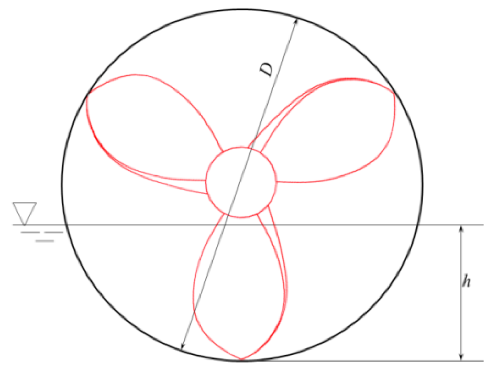
. are basic parameters of SPP. They are defined as immersion of propeller, diameter of propeller, revolution rate of propeller, kinematic viscosity of water, gravitational constant and capillarity constant of water, respectively. The immersion of propeller is defined as the ratio of the distance between free surface and propeller blade tip to propeller diameter, as shown in Figure 1.
In general, the surface-piercing propeller is positioned in which the waterline passes right through the propeller hub when the craft is sailing under normal conditions, which means that each blade is out of water in half the time of each propeller rotation. While one blade is revolving one circle around, the propeller blade brings the air bubble into the vacuum cavity region, generating an air cavity. One side of the cavity is connected to the atmosphere and the other to the blade. The water shock effect on the blade is suppressed, when the air entrained in the cavity compresses with the air cavity compressed. In fact, it is proved that propeller operating in the cavitation situation is more efficient than that under the immersed condition. Due to the influence of the attitude changes of the craft body, it is impossible to ensure that SPP is right in the position of ventilation state. Once the propeller is fully immersed in the water, the torque increases sharply. An approach that equipped an artificial air vent pipe in front of the propeller can accomplish the purpose of reducing torque. Meanwhile, it is also possible to reduce torque by changing pipe diameters.

2.2. Geometry

In the numerical calculation, the target propeller model is an SPP-1 surface-piercing propeller. The rotation direction is right-handed. The basic parameters of the SPP-1 surface-piercing propeller are shown in Table 1.
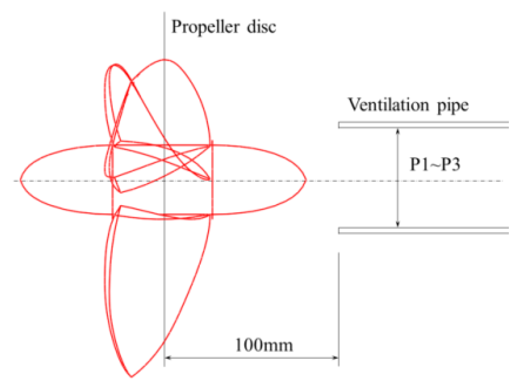
The geometry of the propeller and the vent pipe is shown in Figure 2. The distance from the outlet of vent pipe to the front of propeller is 100 mm, and the chosen ventilation pipe diameter are P1 (30 mm), P2 (40 mm), and P3 (50 mm), respectively. For comparison, there is a P0 case that represents SPP-1 operating under the full immersion condition without ventilation.

2.3. Governing Equations

The governing equation for the conservation of mass can be written as Equation (5):
ρ t + · ( ρ μ ) = S m ,
where ρ . is the water density, μ is the velocity component in each direction, and t . is the time. S m is the added mass attached to continuity term, which is defined as zero in some cases.
The governing equation for the momentum conservation can be written as Equation (6):
t ( ρ μ i ) + x j ( ρ μ i μ j ) = p x i + Γ i j x j + ρ g i + F i ,
where g i . is the gravitational acceleration, F i is the body forces, μ is the dynamic viscosity, and Γ i j is the Reynolds stress tensor.
Γ i j = μ ( μ i x j + μ j x i ) 2 3 μ μ i x i σ ij ,
where σ i j is the Kronecker delta.
Considering the equations above, the Reynolds averaged momentum equation is defined as Equation (8):
t ( ρ μ i ) + x j ( ρ μ i μ j ) = p x i + x j ( μ μ i x j ρ μ i μ j ¯ ) + F i .
It is significantly noticed that the term μ i μ j ¯ is associated with the turbulence flow. Thus, a relevant turbulence model approach should be proposed.
In this paper, the k - ω based Shear Stress Transport (SST) model is required for the propeller turbulence calculation. The k - ω SST model is deduced by Menter at el. [24]. It is a blending function that is coupled with the k - ω and k - ε models. The SST model applies the k - ω model which has good performance to calculate far field, while using the k - ε . model to solve the near wall region problems. These approaches are based on the RANS turbulence model for monitoring the hydrodynamic performance of flow.

2.4. Free Surface Modeling

The vent pipe keeps the propeller in the air-water two phase flow region under the fully immersed condition. For the interface of water and air, the volume of fluid (VOF) model is adopted, whose basic principle is to determine the free surface by capturing the fluid and mesh volume ratio function in the grid. Otherwise, air and water are considered as incompressible fluids:
  • C = 1 , volume completely filled with reference phase,
  • C = 0 , volume completely not filled with reference phase,
  • 0 < C < 1 , volume partially filled with reference phase.
Due to the individual identity of each fluid particle, the material derivative should be zero with the communication in the volume fraction C :
C t + V · C = 0 .
Once the volume fraction is determined, the real density and viscosity calculated in each grid can be obtained as Equation (10):
ρ e f f = ρ g C + ρ f ( 1 C ) ,
μ e f f = μ g C + μ f ( 1 C ) .

2.5. Hydrodynamic Parameters

While predicting the hydrodynamic performance of the SPP, a series of momentous parameters should be calculated as follows:
Advance speed coefficient:
J = V A n D ,
Thrust coefficient:
K t = T ρ n 2 D 4 ,
Torque coefficient:
K q = Q ρ n 2 D 5 ,
Promote efficiency:
η = J 2 π K t K q ,
where V A , n , K t , K q , and η are the forward speed of propeller, revolution rate of propeller, thrust coefficient, torque coefficient and efficiency, respectively.

2.6. Grid Generation and Boundary Conditions

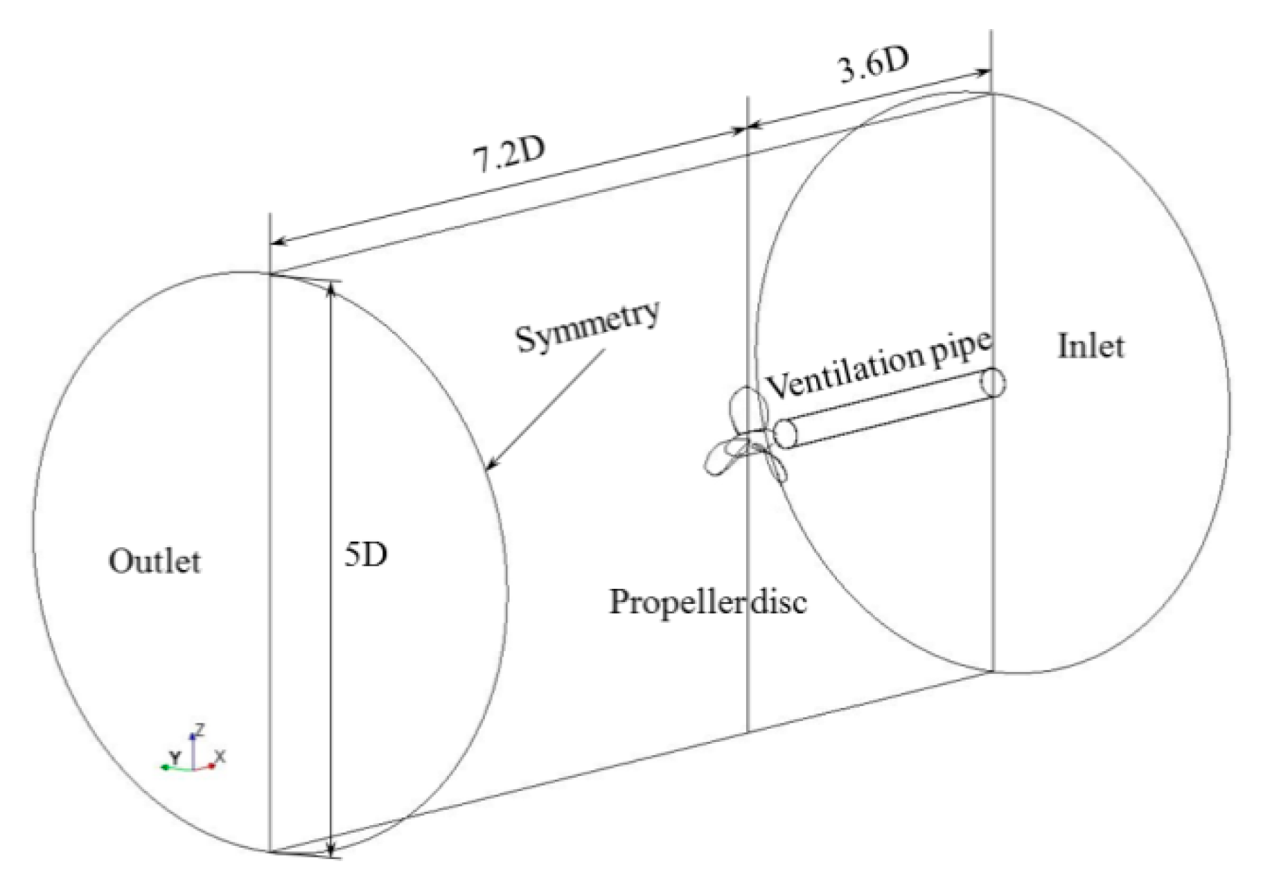
For the accurate numerical simulation, the region is generated pertinently to monitoring the fully developed flow flowing through the propeller. The computational domain is divided into two parts. They are the external cylindrical stationary region and the interior cylindrical rotating region with the propeller inside. The computational domain and boundary conditions are shown in Figure 3. The diameter of external stationary region and interior rotating region is 5.0D and 1.2D, respectively. The distance between the velocity inlet and propeller plane is 3.6D, while that between the pressure outlet and plane is 7.2D. For the rotating region, the two sides of cylindrical surfaces are 0.45D to the propeller surface.
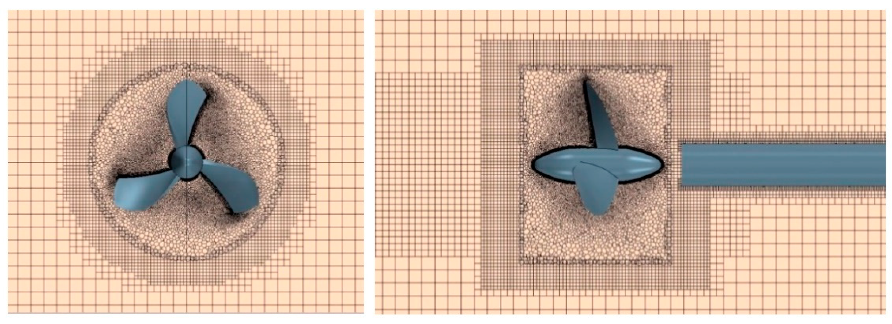
Due to the stationary region and rotating region having a relative motion during the propeller revolution, the overlapping mesh method was chosen to approach the effectiveness of information exchange. The mesh size of overlapping grid connected with two regions should be the same as much as possible. The quadrangular structured mesh was employed in the stationary region, which satisfies the developed flow after the propeller, while the polyhedral mesh was generated in the rotating region for flowing around the propeller. For checking the mesh independency, there are several cases of meshing that were simulated that are expounded in the following section: the cross-section views of volume mesh are shown in Figure 4.

2.7. Mesh Independency and Grid Convergence

Considering the accuracy of the unstructured mesh near the propeller surface, the term Y+ is proposed for judging the grid near the wall. The Y+ value is defined as Equation (16):
Y + u * y ν ,
where u * is the velocity at the nearest wall, y is the distance to the nearest wall, and ν is the fluid kinematic viscosity. The Y+ value on the blade surface should be between 30 and 300. The growth factor of the distances adjacent to two grids should be 1.10. Thus, the first boundary layer grid distance on the blade is calculated as following Equation (17):
y = L · Y + · 74 · ( R e ) 13 14 ,
where y is the first grid distance, and L is the characteristic length.
In this study, a series of meshing generated for several Y+ values are demonstrated in Table 2. The calculated parameters, thrust coefficient K t and torque coefficient 10   K q , impairing propulsion efficiency are compared with the experiment results by Ghassemi et al. [2]. Ghassemi et al. [2] carried out experiments on three bladed propellers (SPP-1) in the immersed condition. The thrust coefficient ( K t ) and torque coefficient ( 10   K q ) are 0.3093 and 0.8579 as shown in Table 2. Table 3 illustrates the numerical simulated results of thrust ( K t ) and torque coefficient ( 10   K q ) for five Y+ cases. In addition, it shows the error of experiment data and simulation data. It is clearly obtained that the error of thrust and torque coefficient are both satisfied in the minimum position when the Y+ is 60. Whether it goes up or down, the accuracy of simulation is decreasing. Thus, it concluded that Y+ is equal to 60 which is the ideal choice to guarantee calculation precision. These data are calculated at J = 1.00 .
It should be considered that the investigation of the numerical grid convergence plays an important role before diving into further research. The numerical simulation was carried out with four different grid numbers. It demonstrated that the simulation results are closer to the experiment data with the increasing of volume grid. Thus, the grid schedule of G4 case is a good choice. However, it is not an excellent choice that a large amount of computing time sacrificed for a tiny accuracy improved. Therefore, the fine mesh G3 is the available scheme that is simultaneously satisfied to the efficiency and accuracy.
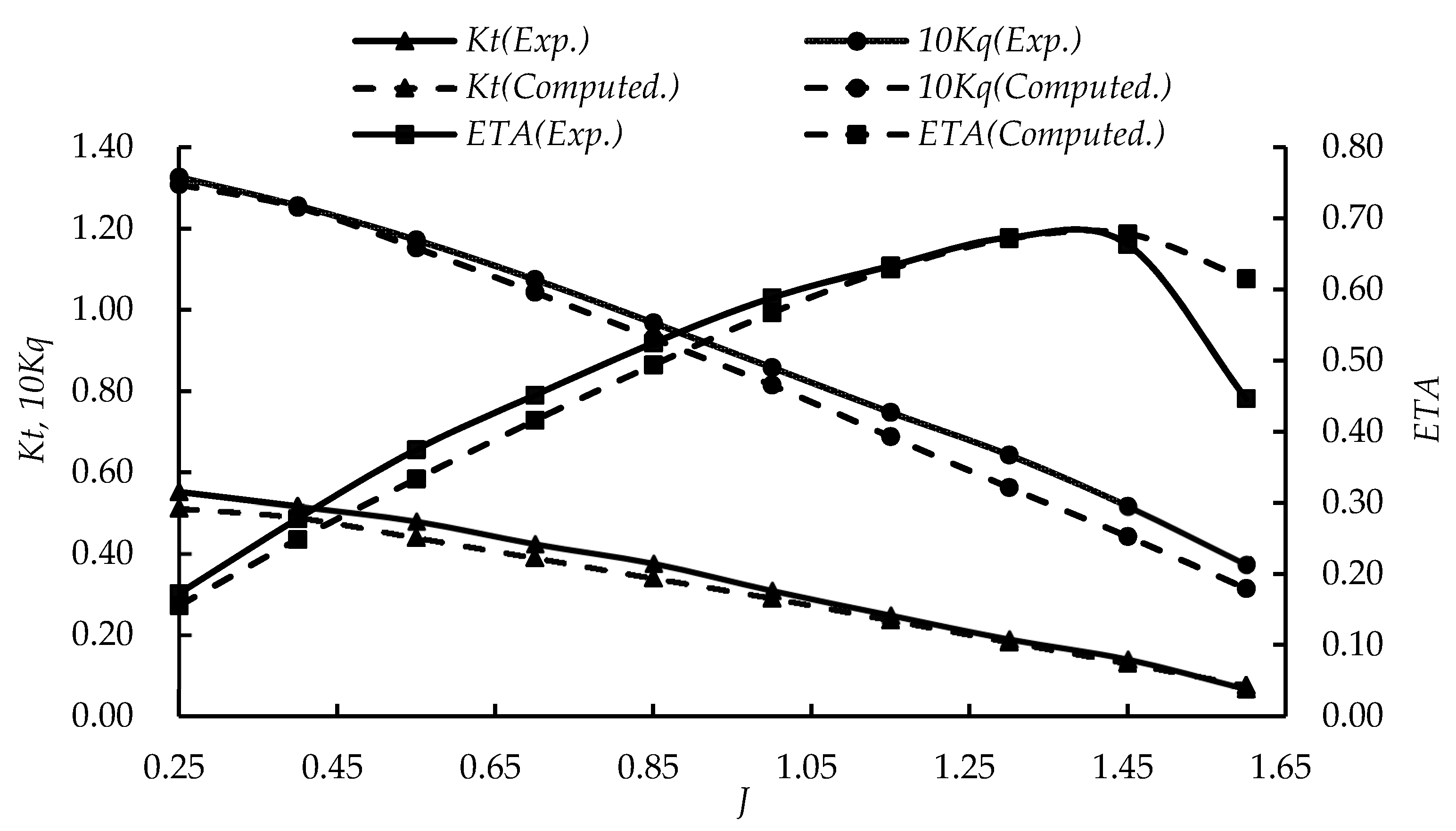
In order to validate the prediction accuracy of the numerical calculation method for the ventilation phenomenon and the air–water interface, the SPP-1 was selected for studying under the condition of full immersion. The advanced rotational speed n is 2400 rpm. There were five different speed coefficients selected from 0.85 to 1.60, which was calculated by Equation (12). In this paper, hydrodynamic results obtained by simulating the surface-piercing under the full immersion condition, which are thrust coefficient, torque coefficient and the open water efficiency, are compared with the existing experimental results by Ghassemi et al. [2].
As shown in Figure 5, the thrust coefficient K t and the torque coefficient 10   K q measured by the CFD method are slightly larger than the experimental ones at a low advanced speed. Conversely, the calculated efficiency η result is slightly smaller than the tests. The results show an accordant tendency for a little receivable error. Considering the complicated flow field, it can be seen that the numerical results agree well with the experimental data. This research demonstrates that the CFD approach can meet the demand for the surface-piercing propeller hydrodynamic prediction.

2.8. Initial Conditions

On the basis of a ventilation phenomenon under the full immersion condition, the liquid around the propeller is flowing in the form of unsteady two-phase flow. The density of water and air is 997.56 kg/m3 and 1.18 kg/m3, respectively. The dynamic viscosity of water and air is 8.89 × 10⁻⁴ Pa-s and 1.86 × 10⁻⁵ Pa-s, respectively. In this paper, due to a function of the artificial vent pipe installation, the velocity inlet was classified as air velocity inlet and water velocity inlet, whose velocities are exactly the same. The volume fraction of each velocity inlet was set to 1 and 0 for volume fraction of water and air, respectively. The pressure outlet was set as reference pressure at the end of the cylindrical stationary region. The other side of the stationary region was set as symmetry. The interface of the SPP blade and vent pipe were set as a non-slip wall. The solution being set up with physical model in Star-CCM+ was summarized in Table 4.
The second-order schemes were employed for implicit unsteady discretization, linear interpolation, and time integration. The time step is defined as 1.5 × 10⁻⁴ s, which satisfies the condition of CFL 1, when the propeller rotates for one degree. The numerical calculation was simulated on a PC with an Intel Xeon CPU X5690 (six cores, 3.46 GHz) (Santa Clara, CA, USA). It cost 60 h for one case simulation.

3. Numerical Results

3.1. Hydrodynamic Performance

As can be seen in Figure 6, the air volume fraction (green region) ejected from the vent pipe flow passes through the hub of propeller; meanwhile, the air stream is swung away by rotating blades. It can be found that, along with the air fraction flowing past from the head of propeller, the air bubbles are adhering to part of the section surface and the thick trailing edge. Due to the relatively lower pressure around them, the air bubbles are aggregated around the propeller and spread out from the root to the edge of blades. Following the blades revolution, three spiral air stream lines are forming and carrying out a complex rotational motion around the air stream adhering to the hub in the wake field. In the initial stage, the air cavities appear by the pressure difference at the hub cap, and the blade tailing is interconnected. In the process of downstream development, the air cavity behind the hub is stretching away from that along the edge, due to the interaction of water and bubbles. With the flow going downstream, these four air stream lines are breaking into smaller scale bubbles until they disappeared in the far field.
Figure 6 displays the air cavity morphology diagram of P1, P2, and P3 in the wake at J = 1.00 . It clearly finds that the air cavity of Figure 6a, whose diameter of ventilated pipe is 30 mm, breaks into small bubbles rapidly after leaving the trailing edge of blade, while the air cavity of Figure 6c, whose diameter is 50 mm, forms a continuous spiral air bubble and centric air stream. It can be seen that the air content is going down gradually along with the far field region. With an increase in the vent pipe diameter, the continuity and integrity of the air cavity have better performance. With increasing the advanced speed coefficient ( J ), it is directly observed that the air bubbles can be fully developed in the wake field.

3.2. Velocity Distribution

In Figure 7, it shows the velocity distribution of the surface-piercing propeller with a 50 mm diameter vent-pipe under the fully immersed condition at J = 1.00 . It is clearly noticed that the velocity of flow near the propeller blade is significantly high. In the wake field, the low speed area (blue color) along the axis direction is the air volume fraction. Due to the rotation of propeller, the air bubbles attached to the blades form three spiral air columns moving toward the wake field. Meanwhile, the bubbles along the center of propeller join together and flow away.
The whole flow region is divided into several planes. It clearly demonstrates the layout of the chosen planes in the region in Figure 7. As shown in Figure 8a, the air in the center of pipe has a higher speed than that near the pipe wall. When it comes across the propeller, the velocity near the hub increases rapidly. In Figure 8d–f, as the air and water flow through the blades, three high speed areas form where the low speed areas wrap around them respectively on the outside. Figure 8h illustrates the velocity distribution in the far field. Three high speed zones merge together forming a ring-shaped high speed area. With downward progress of wake flow, a high speed annular area appears.
The velocity distribution of propeller and tail region completely meets the hydrodynamic performance of water and air bubbles in Figure 6. Near the propeller, one air column from vent pipe and three helical air bubbles formed by rotating blades flow away at high speed. In the wake field, the air bubbles come together and form a high annular column.
Figure 9a demonstrates the flow velocity distribution near the propeller surface. Figure 9b,c show the velocity distribution cloud and vector at the 0.5R section. Figure 9d,e reveal the velocity distribution cloud and vector at the 0.1R section. It is clearly noticed that the velocity around the leading edge is high. Meanwhile, there is a high speed area that appeared around the tailing edge. The high speed flow leads to a low pressure area existing and the air bubbles tend to gather together in this area. They are attached to the suction surface of blades. With the propeller rotating, the bubbles spiral to the wake field.

3.3. Pressure Distribution

As shown in Figure 10, the green and red region represent the distribution of air and water volume fraction on the blades for P1, P2, and P3 at J = 1.00 , respectively. According to the hydrodynamic performance of wake flow shown in Figure 6, the air bubbles bypass and gather at low pressure area leading to the messy pressure distribution on the trailing edge of the blade. Due to the influence of the ventilated pipe, the air bubble which is stuck on the blade surface forms a helical air cavity. In Figure 10, it can find that the air bubble attaches to the trailing edge with ventilation, leading to the increase of pressure and uniform pressure distribution on the edge surface. The flowing air covers the root of propeller blades, leading to the root of blades being in a ventilation state and increasing the pressure in this area. Comparing with the results in Figure 10a,b, the variation of air volume distribution changes slightly with the increase of a ventilated pipe diameter on the pressure surface. When the large air bubble is dispersed on the suction surface, the air coverage is expanded because of the rotating blades cutting the bubbles into small pieces.
Figure 11 illustrates the pressure distribution cloud on the pressure surface and suction surface at J = 1.00 for the ventilated SPP. One can find that, on the pressure surface, the high pressure is mainly fastened on at the nearby leading edges of blades, while, at the thick trailing edge, the pressure distribution is negative. It portrays that the low pressure area shrinkage appears due to the installation of the vent pipe. Furthermore, the low pressure area is diminishing steadily with the augment of diameter of the vent pipe. The high pressure zone around the root remains roughly the same shape as the air adheres to it.

3.4. Hydrodynamic Parameters

In the paper, the numerical simulation was carried out on the vent pipe diameter of 30 mm, 40 mm, and 50 mm denoted as P1, P2, and P3, respectively, under the fully immersed condition. Moreover, an extra case P0 was studied for reference under no ventilation condition. Table 5 shows the hydrodynamic results of four different diameter operations at J = 0.85 1.30 . As one can see in Table 5, the thrust coefficient K t . and torque coefficient 10   K q . have a descending trend from high to low value under the ventilation condition. When the advanced speed coefficient J is equal to 0.85, 1.00, and 1.15, K t . and 10   K q show a tendency to reduce with the augment of the diameter of a vent pipe. It means that, at the same speed, the larger pipe diameter leading to a mass of air bubbles inlet brings a higher output coefficient value, i.e., thrust and torque coefficient. On the contrary, compared with P3 and P1, the tendency of K t and 10   K q is increasing obviously at J = 1.30 . It means that the ventilated pipe has little effects on the operating efficiency of SPP. The advanced speed coefficient directly generates pressure alteration on the root of blades. The influence of ventilation on pressure distribution at high speed is weaker than that at low speed.
Figure 12 plots the efficiency calculated by Table 5. Compared with the without ventilation condition, the surface-piercing propeller has a low efficiency on the thrust distribution at J = 0.85 . The reason for this phenomenon is that the thrust coefficient is affected significantly by the ventilation at a low speed. The large air bubbles from the artificial vent pipe are around the propeller blades. Due to the low speed, these large bubbles are difficult to flush into the tail field. They gather around the hub and propeller blades. These clustered bubbles lead to the propeller’s propulsion being reduced. For J = 0.85, the thrust coefficient of the propeller with a vent-pipe is weaker than that without a pipe. It can be seen that the efficiency of them are not distinctly different whether the propeller is equipped with a vent-pipe or not. With increasing of the advanced speed coefficient J , the efficiency of propeller η would improve obviously. It can find that the larger the diameter is, the higher the efficiency is.

3.5. Pulsation Characteristics

The pulsation force of the surface-piercing propeller is distinctly dependent on the concentration of ventilation volume. In this paper, the thrust coefficient K t 0 and torque coefficient K q 0 , which are obtained by SPP-1 rotating simulation without ventilation at J = 1.00 are regarded as the reference. Figure 13 displays the ratio of force and moment coefficient which is generated by results under ventilated conditions compared with the reference.
As can be seen from Figure 13a,b, these curves show the fluctuation of axial force and moment. It is clearly noticed that the undulation range of P3 curve is significantly smaller than the others. It shows that the axial force and moment of P3 curve are the most stable, followed by the P1 curve, while the force curve of P2 vibrates violently. In addition, the force of P3 has the highest mean value of these three curves. It is explained that the thrust and torque coefficient of SPP-1 produce grievous vibration with the increase of ventilated pipe diameter. The influence of larger ventilated pipe diameter extends the oscillating period of thrust and torque coefficient. The horizontal and vertical forces for P1 and P2 present definite regularity compared to P3, shown in Figure 13c,e. It can be seen clearly that increasing ventilation pipe diameter can reduce the peak for lateral force. In the vertical direction, the pulsation force and moment are irregular, the maximum of P1 and P3 are almost in the same level.
For the force acting on the blades, increasing the diameter of the ventilated pipe leads to an increase in the vibration amplitude, while it will greatly reduce the peak of force. In terms of hydrodynamic performance, the wake stream after the propeller is more regular and continuous for a large ventilated pipe compared with that for a small one. Due to the different properties of water and air, the thrust and torque coefficient get an even bigger boost by more air bubbles adhering to the blades. The air bubbles are fully extended in the far field, leading to optimization of the thrust and torque. Above all, the results of the influence on ventilated pipe P3 have better performance than P1 and P2 for the present comparison.

4. Conclusions

In this paper, the flow around a surface-piercing propeller was investigated to study the hydrodynamic performance of an artificial ventilated pipe for various pipe diameters using the CFD technique of Finite Volume Method and the two-phase VOF model. The results of the numerical simulation were compared with existing experimental data by Ghassemi et al. [2]. In the previous study of Ghassemi et al. [2] and Young et al. [14,15,16], the surface-piercing propeller rotates across the free water surface under the naturally ventilated condition. Each blade operates through water surface twice in one stroke, while, in this study, the surface-piercing propeller, which installs an artificial vent pipe in front of the propeller disc, rotates in full immersion conditions. All blades rotate through the air bubbles in the air flow direction. The hydrodynamic performance of artificial ventilated SPP is different from those given in literature. The main conclusions are summarized as follows:
  • The Finite Volume Method, turbulence model SST, overlapped mesh method and a two-phase VOF model can accurately predict the ventilated surface-piercing propeller in full immersion conditions.
  • In the wake field of the ventilated surface-piercing propeller, three spiral air stream lines are forming and carrying out a complex rotational motion around the air stream adhering to the hub. With the flow going downstream, these four air stream lines are breaking into smaller scale bubbles until they disappear in the far field. With increasing the vent pipe diameter, the continuity and integrity of the air cavity have better performance. With increasing the advanced speed coefficient ( J ), it is directly observed that the air bubbles can be fully developed in the wake field.
  • After the ventilation equipment working, the thrust coefficient K t . and torque coefficient 10 K   q are decreased significantly. At low advanced speed, K t and 10   K q show a tendency to reduce with the growth of diameter of vent pipe, and the propeller has a low efficiency on the thrust distribution. However, at high speed, the tendency of K t and 10   K q is increasing obviously. The efficiency of propeller η would improve obviously. It can find that the larger the diameter is, the higher the efficiency is.
  • Increasing the diameter of ventilated pipe leads to an increase in the vibration frequency, while it will greatly reduce the amplitude of the force. There is no denying that increasing the vent-pipe diameter has a positive effect on the propulsion efficiency of the surface-piercing propeller. The numerical simulation results demonstrate the effectiveness of increasing the ventilated pipe diameter approach for improving the hydrodynamic performance of the artificial ventilated surface-piercing propeller.

Author Contributions

Conceptualization, D.Y.; methodology, Z.G.; software, Z.G. and Y.D.; validation, Z.G. and D.Y.; data curation, Z.G. and Y.D.; writing—original draft preparation, Z.G.; writing—review and editing, Z.G. and D.Y.; visualization, Z.G. and Y.D.; funding acquisition, P.L.

Funding

This research was funded by the National Natural Science Foundation of China (Grant No. 51509053, No. 51579056, and No. 51579051).

Conflicts of Interest

The authors declare no conflict of interest. The funders had no role in the design of the study; in the collection, analyses, or interpretation of data; in the writing of the manuscript, or in the decision to publish the results.

References

  1. Ding, E.B.; Tang, D.H.; Zhou, W.X. A review of research on semi-submerged propellers. J. Ship Mech. 2002, 6, 75–84. [Google Scholar]
  2. Ghassemi, H.; Shademani, R. Hydrodynamic characteristics of the surface-piercing propellers for the planing craft. J. Mar. Sci. 2009, 8, 267–274. [Google Scholar]
  3. Yang, D.M.; Zhen, R.; Guo, Z.Q.; Gao, Z.Y. Numerical Analysis on the Hydrodynamic Performance of an Artificially Ventilated Surface-Piercing Propeller. Water 2018, 10, 1499. [Google Scholar] [CrossRef]
  4. Olofsson, N. Force and Flow Characteristics of a Partially Submerged Propeller. Ph.D. Thesis, Chalmers University of Technology, Göteborg, Sweden, February 1996. [Google Scholar]
  5. Dyson, P.K. The Modeling Testing and Design of a Surface Piercing Propeller Drive. Ph.D. Thesis, Plymouth University, Plymouth, UK, October 2000. [Google Scholar]
  6. Peterson, D. Surface Piercing Propeller Performance. Master’s Thesis, Naval Postgraduate School, Monterey, CA, USA, September 2005. [Google Scholar]
  7. Zhao, R.; Faltinsen, O. Water entry of two-dimensional bodies. J. Fluid Mech. 1993, 246, 593–612. [Google Scholar] [CrossRef]
  8. Yari, E.; Ghassemi, H. Numerical analysis of surface piercing propeller in unsteady conditions and cupped effect on ventilation pattern of blade cross-section. J. Mar. Sci. Technol. 2016, 21, 501–516. [Google Scholar] [CrossRef]
  9. Furuya, O. A performance prediction theory for partially submerged ventilated propellers. J. Fluid. Mech. 1985, 151, 311–335. [Google Scholar] [CrossRef]
  10. Wang, D. Water entry and exit of a fully ventilated foil. J. Ship. Res. 1977, 21, 46–68. [Google Scholar]
  11. Wang, D. Oblique water entry and exit of a fully ventilated foil. J. Ship. Res. 1979, 23, 43–54. [Google Scholar]
  12. Wang, G.; Zhu, X.; Sheng, Z. Hydrodynamic forces of a three dimensional fully ventilated foil entering water. J. Hydrodyn. 1990, 2, 186–195. [Google Scholar]
  13. Wang, G.; Zhu, X.; Sheng, Z. Hydrodynamic performance of partially submerged ventilated propeller. Shipbuild. China 1990, 109, 22–31. [Google Scholar]
  14. Young, Y.L.; Savander, B.R. Numerical analysis of large-scale surface-piercing propellers. Ocean Eng. 2011, 38, 1368–1381. [Google Scholar] [CrossRef]
  15. Young, Y.L.; Kinnas, S.A. Analysis of supercavitating and surface piercing propeller flows via BEM. J. Comput. Mech. 2003, 32, 269–280. [Google Scholar] [CrossRef]
  16. Young, Y.L.; Kinnas, S.A. Numerical analysis of surface piercing Propellers. In 2003 Propeller and Shaft Symposium.; Society of Naval Architects and Marine Engineers: Virginia Beach, VA, USA, 2003. [Google Scholar]
  17. Broglia, R.; Dubbioso, G.; Durante, D.; Mascio, A.D. Simulation of turning circle by CFD: Analysis of different propeller models and their effect on maneuvering prediction. Appl. Ocean. Res. 2013, 39, 1–10. [Google Scholar] [CrossRef]
  18. Caponnetto, M. RANSE simulations of surface piercing propellers. In Proceedings of the 6th Numerical Towing Tank Symposium, Rome, Italy, 29 September–1 October 2003. [Google Scholar]
  19. Himei, K. Numerical analysis of unsteady open water characteristics of surface piercing propeller. In Proceedings of the 3rd International Symposium on Marine Propulsors SMP, Lauceston, Australia, 5–7 May 2013; pp. 292–297. [Google Scholar]
  20. Alimirzazadeh, S.; Roshan, S.Z.; Seif, M.S. Unsteady RANS simulation of a surface piercing propeller in oblique flow. Appl. Ocean Res. 2016, 56, 79–91. [Google Scholar] [CrossRef]
  21. Yuan, Y.M.; Wang, C.; Zhen, R. Influence of diameter of vent pipe on hydrodynamic characteristics of surface piercing propeller. J. Harbin Eng. Univ. 2019, 40, 227–233. [Google Scholar]
  22. CD-adapco Group. STAR-CCM User Guide Version 9.06; CD-adapco Group: Melville, NY, USA, 2014. [Google Scholar]
  23. Shiba, H. Air-Drawing of Marine Propellers; Transportation Technical Research Institute: Wuhan, China, 1953. [Google Scholar]
  24. Menter, F.R. Zonal two-equation k-ω turbulence model for aerodynamics flows. In Proceedings of the 23rd Fluid Dynamics, Plasmadynamics, and Lasers Conference, Orlando, FL, USA, 6–9 July 1993. [Google Scholar]
Figure 1. Definition of the immersion of the propeller h and the propeller diameter D .
Jmse 07 00240 g001
Figure 2. The geometry of the propeller and vent pipe.
Jmse 07 00240 g002
Figure 3. Computational domain and boundary conditions.
Jmse 07 00240 g003
Figure 4. Cross-section views of volume mesh.
Jmse 07 00240 g004
Figure 5. Comparison of Computational Fluid Dynamic (CFD) and experimental results at full immersion.
Jmse 07 00240 g005
Figure 6. The wake after the ventilated propeller at full immersion. (a) the diameter of ventilated pipe P1 is 30 mm; (b) the diameter of ventilated pipe P2 is 40 mm; (c) the diameter of ventilated pipe P3 is 50 mm.
Jmse 07 00240 g006
Figure 7. Velocity distribution of the vertical section.
Jmse 07 00240 g007
Figure 8. Velocity distribution of cross section. (Plane location is shown in Figure 7.); (a) Plane a at 0.5D section; (b) Plane b at 0.375D section; (c) Plane c at mid-section; (d) Plane d at -0.5D section; (e) Plane e at -D section; (f) Plane f at -1.5D section; (g) Plane g at -2D section; (h) Plane h at -4D section.
Jmse 07 00240 g008
Figure 9. (a) velocity distribution of blade cross section; (b) velocity distribution cloud at the 0.5R section; (c) velocity distribution vector at the 0.5R section; (d) velocity distribution cloud at the 0.1R section; (e) velocity distribution vector at the 0.1R section.
Jmse 07 00240 g009aJmse 07 00240 g009b
Figure 10. The volume fraction on the blades at J = 1.00 . (a) the volume fraction on the pressure surface; (b) the volume fraction on the suction surface.
Jmse 07 00240 g010
Figure 11. The pressure distribution on the blades at J = 1.00 . (a) the pressure distribution on the pressure surface; (b) the pressure distribution on the suction surface.
Jmse 07 00240 g011
Figure 12. Efficiency curve for SPP-1 under ventilation conditions.
Jmse 07 00240 g012
Figure 13. Pulsation characteristics during revolution for ventilated SPP at J   =   1 . 00 . (a) axial force; (b) axial moment; (c) lateral force; (d) lateral moment; (e) vertical force; (f) vertical moment.
Jmse 07 00240 g013aJmse 07 00240 g013b
Table 1. Surface-piercing propeller (SPP-1) propeller geometric parameters.
Diameter D200 (mm)Pitch Ratio P/D1.6 (-)
Number of leaves Z3 (-)Hub diameter ratio d/D0.2 (-)
Disk ratio AE/AO0.5 (-)Ventilated pipe diameter P130 (mm)
Side angle/°0 (°)Ventilated pipe diameter P240 (mm)
Tilt angle/°10 (°)Ventilated pipe diameter P350 (mm)
Table 2. Error results for different Y+ values.
Y+ K t 10   K q Error   K t Error   10   K q
Exp.0.30930.8579
400.28160.7585−9.84%−13.10%
500.28500.7833−8.53%−9.52%
600.29050.8149−6.47%−5.28%
700.28920.7866−7.01%−9.06%
800.27650.7758−11.86%−10.59%
Table 3. Results from the grid convergence.
CaseNumber of Mesh K t ε K t 10   K q ε K q
G11,280,0000.279310.74%0.762312.54%
G22,500,0000.28478.64%0.773110.97%
G34,200,0000.29056.47%0.81495.28%
G46,000,0000.30013.07%0.80696.32%
Table 4. Settings used in Star-CCM+.
ParameterMethodDiscretization
1 General settingImplicit Unsteady, Segretated Flow
2 Turbulent modelTurbulent Shear Stress Transport (SST) K-Omega
3 MultiphaseVolume of Fluid (VOF)
Eulerian Multiphase
4 Solution methodImplicit UnsteadySecond Order
Table 5. Effect of vent pipe diameter.
J . 0.851.001.151.30
K t P00.33960.29050.23670.1897
P10.32620.28070.23170.1828
P20.32340.27830.23140.1845
P30.31990.27490.23080.1867
10   K q P00.92970.81490.68790.5629
P10.88760.77460.65890.5433
P20.86900.75700.64810.5391
P30.85160.74020.64070.5412

