1. Introduction
1.1. Background
As humanity faces the global threat of climate change, society needs to drastically reduce the emission of greenhouse gases (GHGs). Maritime transport currently contributes to about 2.7% of the global anthropogenic carbon dioxide (CO
2) emissions [
1], but this share might increase as a consequence of the de-carbonization of other sectors and in correspondence with an absence of actions in the shipping business.
As of today, ships are still almost entirely powered by fossil fuels. Most recently, the International Maritime Organization (IMO) officially adopted an initial strategy aimed at reducing GHG emissions from shipping by 50% by 2050, compared to the levels of 2008 [
2]. A sharp change in the way ships are designed and operated is necessary to reach this goal.
The ship machinery system is the largest source of GHG emissions on board a vessel, and has a significant impact on its fuel consumption. Therefore, the selection of a proper machinery system is one of the most critical decisions to be made during the ship design phase. A machinery system investigation is conducted in every ship design project, with the aim of identifying the most suitable set of propulsion and auxiliary engines to be installed on board according to the ship’s route and layout.
There are several ways to conduct a machinery study, but usually the process consists of the following steps, not necessarily conducted in the order mentioned:
Recognizing the potential engine alternatives to be compared;
Estimating the fuel consumption with the chosen alternatives;
Estimating the costs of the alternatives;
Evaluating the impact of the alternatives on the ship layout.
The optimal configuration is not necessarily the cheapest, because all the aspects mentioned influence the choice. The ship owner might also have demands based on its current fleet, such as request for a specific engine manufacturer or engine type, due to reasons such as previous positive (or negative) experiences, crew expertise; or considerations related to maintenance and availability of spare parts.
In addition, other practical aspects should be taken into account, such as choosing the same engine type for all engines on a given ship enables the minimization of the number of spare parts required on board. Depending on the extent of the project, the machinery study can be a relatively fast process (made by a specialist within a few days), or extend over longer periods of time. However, even in the most extensive studies, the comparison between various alternatives is usually limited, because it requires significant amount of manual work.
Consequently, the introduction of tools to support the designers with automated analyses and optimization routines could substantially increase the quality of the decisions taken during these earliest phases of the ship design process.
These tools could either enlarge the range of options to be considered during the machinery selection process, or introduce efficient calculation methods as a way to make the selection process less time consuming.
1.2. Previous Research
Several authors proposed the use of mathematical optimization techniques in the early phases of the ship design process. Ölçer [
3] presented the problem of identifying the optimal main design parameters of a ship’s machinery system as a multi-objective, combinatorial optimization problem, and suggested different methods for handling the trade-offs between different objectives.
Given the high uncertainty that characterizes the early ship design phases, several authors focused on the optimal choice of a ship’s main features, such as length, breadth, draft, design speed, under uncertainty. Diez and Peri [
4] developed a robust design optimization framework to derive optimal vessel design configurations, which preserve good performance under a large number of uncertain parameters characterized by wide uncertainty ranges. The work underlined the importance of taking into account the uncertainty of the input data when carrying out the optimization procedure, and was carried out by using a particle swarm optimizer. Hannapel and Vlahopoulos [
5] applied reliability-based design and robust optimization approaches to a bulk carrier conceptual design case, proving that these methods could be implemented effectively to address ship design problems. Their results emphasize, once more, the need to consider the impact of uncertainty parameters during the multidisciplinary ship design process.
Boulougouris et al. [
6] proposed a tool for optimizing ship main parameters, i.e., energy efficiency, based on a combination of heuristics and statistical analyses of past ship designs and known modelling approaches for ship propulsion. Both this work and the one from Ölçer [
3] acknowledged the importance of the human expertise in the design process and proposed an approach to support decision makers.
Based on the existing literature on the optimization of the ship machinery system, it appears that two alternative approaches have been studied most widely: mixed-integer linear programming (MILP) and mixed integer non-linear programming (MINLP). MILP refers to problems where: (1) the objective function is linear; (2) all constraints (both equality and inequality) are linear; and (3) some of the variables can only take integer values. An MILP problem is generally solved based on the application of a branch-and bound method. Each branching and bounding iteration involves the resolution of a linear programming (LP) problem, where the integrality condition is relaxed. This makes MILPs particularly powerful tools for exploring very wide search spaces, while ensuring the identification of the global optimum.
Several authors employed an MILP approach for the optimization of ship machinery systems. Solem et al. [
7] developed a model for selecting engine configurations for a diesel-electric machinery system for conceptual design purposes. The results of their study suggested that the use of optimization techniques could give valuable support to the ship designers during the machinery selection process. The works of Baldi et al. [
8,
9] proposed the use of MILP-based optimization approaches for the design of cruise ships, showing the potential for including a larger number of elements, such as the use of fuel cells, the limitation of dynamic loads on specific components [
8] and the optimal integration of heating and cooling demands using process integration [
9].
The main downside connected with the MILP approach is that most real problems cannot be treated as linear, or doing so involves strong approximations. While some solutions are available for dealing with non-linearity while keeping a MILP approach (e.g., piece-wise linearization, as in the work of Solem et al. [
7]), these tend to result in an increase in the number of integer variables and, consequently, in a longer computational time required to identify a solution. In addition, some non-linear aspects of ship machinery systems cannot be easily linearized.
For this reason, many authors proposed the use of non-linear approaches, such as the implementation of MINLP. Ancona et al. [
10] utilized a genetic algorithm to optimize the load allocation of the various energy utilities on board a cruise ship. Their study considered a fixed machinery layout, where the load of the different engines could be optimized. Moreover, the possibility to include in the system either thermal storage, or an absorption chiller was evaluated. Baldi et al. [
11] presented a generic method for the optimal load-sharing of the machinery system of a ship for fulfilling all mechanical, electric and thermal power requirements. The method included the use of simplified non-linear correlations for the efficiency of the various components, and the non-linear problem was solved with a combination of SQP (sequential quadratic programming) and branch and bound methods.
Trivyza et al. [
12] proposed a tool for decision support in the early stages of ship design. The tool is based on non-linear optimization, carried out using a genetic algorithm (GA), and included not only the engines, but also different types of components for the abatement of the engine’s emissions. The problem was defined as a multi-objective optimization and was set to evaluate also the environmental impact of the ship machinery system. Zahedi et al. [
13] proposed the use of non-linear optimization to carry out simultaneously the design and the operational optimization of an electric propulsion systems, including a combination of batteries and diesel engines for power supply.
Dimopoulos et al. [
14] described a method to carry out the synthesis, design and operation optimization of an integrated energy system of a vessel based on the MINLP approach and showed that the optimal solution is highly affected by the selected fuel price. The same approach was used also for a liquefied natural gas carrier [
15,
16] and was later extended to a general purpose modelling framework for marine energy systems that can be used for assessment and optimization of design and operation problems in existing vessels, new buildings and novel technologies [
17].
Finally, Tillig et al. [
18] developed a method that can be used to assess the energy efficiency of a vessel in both early design phase and during operation. In this case, the ship performance is modeled in two parts: one for the assessment of a ship’s energy consumption based on an ordinary static power prediction, and one for advanced operational analysis, considering hydrodynamics and machinery systems effects.
The review of the aforementioned literature indicates that researchers in the field have successfully applied both the MILP and the MINLP approaches for similar purposes. However, to the best of our knowledge, there is no study that critically compares the two approaches and defines which technique is the most suitable for the optimization of the selection and operation of marine machinery systems.
1.3. Aim
An optimization framework is presented in this paper, supporting decision making at the earliest stages of the ship design process. The framework is suitable to perform the screening and the selection of the optimal machinery configuration and of its operation for a predefined ship operational profile. The optimal design and operation of a ship’s machinery system was estimated both by linearizing the optimization domain, and by conserving its inherent non-linearity.
Previous works presented in literature aimed at identifying the optimal machinery system configuration to be installed on board a vessel by using either a MILP [
7,
8,
9] or MINLP approach [
10,
11,
12,
13,
14,
15,
16,
17], but did not quantify the inaccuracies in the attained solutions due to the linear approximations, nor clarified which approach is the most suitable for the considered problem.
This work, by implementing both the linear and the non-linear programming techniques, enables the comparison of the solutions obtained by implementing the two approaches, and the definition of the best use-case for each approach. The comparison between the two techniques focuses on the evaluation of their suitability for the selection of the proper machinery system on board a vessel, and for the selection of the unit scheduling leading to the minimum fuel consumption on an annual basis. Computational efficiency of the two approaches is not considered in the comparison (see
Section 4 for further discussion on this point). The findings of the work provide both researchers and industry with a clearer overview of the suitability of the two analyzed optimization approaches in the domain considered. In addition, the best use-cases identified for the two optimization approaches support the development of future design support tools tailored for maritime applications.
The article is structured as follows:
Section 2 describes the applied methods. The attained results are presented in
Section 3 and discussed in
Section 4. Finally, conclusions are outlined in
Section 5.
2. Methods
2.1. Problem Description
The problem can be stated as the choice of the propulsion system type, the number and type of engines installed, and the load of each engine along the various sailing modes.
As a general case, the ship machinery system is expected to fulfil the ship energy demand in terms of propulsion and hotel power, the latter representing the share of electricity required for onboard use. Two alternative configurations of the machinery system are possible: mechanical propulsion (MP), and Diesel-electric propulsion (DEP). In the case of mechanical propulsion, the main propulsion engine(s) (MPE) is/are coupled to a shaft line that is connected to the propeller. The direct coupling of the engine(s) to the shaft line minimizes transmission losses due to the lower number of components. Based on the required rotational speed of the propeller, the layout is marginally different based on the type of engine installed. Two-stroke engines operate at low speed and can be directly coupled to the propeller, while four-stroke engines operate at higher speeds and require the use of a gearbox, thereby including a small transmission efficiency penalty. The use of a gearbox allows for several main engines to be connected to a single propeller.
In the case of mechanical propulsion, the hotel power is produced by using diesel-generator sets, commonly called auxiliary generators. The production of the hotel power is associated with several losses, including losses in the alternating current (AC) generators and in the switchboard. In this paper, for the sake of simplicity, all losses related to hotel power production were lumped in the “generation losses” term.
Auxiliary generators are not, however, the only way to generate auxiliary electric power in a mechanical propulsion system. Mechanical propulsion engines can also be employed for the production of hotel power by using a “power take-off” (PTO) system from the shaft. In this case, if the main engine or engines are operated at variable speed, and the electricity is produced to an AC grid, a variable frequency drive (VFD) is required, in addition to the PTO. This adds to the losses related to the PTO, but ensures higher efficiency to the main engines.
The opposite principle is also possible: the auxiliary generators can be used to boost the propulsion power production, via a “power take-in” (PTI) system. In this case, there are losses included both in the energy conversion from mechanical energy to electricity and in the PTI for transmitting the electricity back to mechanical power. Nevertheless, the PTI is a useful way to ensure that there is the necessary thrust available for the ship in all sailing conditions, enabling the dimensioning of the main engines according to their most commonly utilized profile/best efficiency operation point. Both the PTO and the PTI concepts allow for a general downsizing of the total installed power, and thereby for a reduction of the engine-related investment costs.
On the other hand, diesel-electric propulsion refers to a machinery concept, where diesel-generator sets are used both for propulsion and for fulfilling the demand of on-board consumers. The generated electricity is distributed via AC or direct current (DC) buses to the various consumers on board, serving both propulsion, via electrical propulsion motors, and hotel consumers. Compared to a mechanical propulsion arrangement, diesel-electric propulsion includes inevitably more conversion losses due to the larger number of installed components. DEP is often utilized for ships that have significant variations in their load profiles, and when the share of the hotel load is considerable. For cargo ships, where the majority of the fuel energy is required for ship propulsion, the diesel-electric propulsion concept might be inherently non-profitable, due to the additional losses in the power transmission from prime movers to the ship propeller.
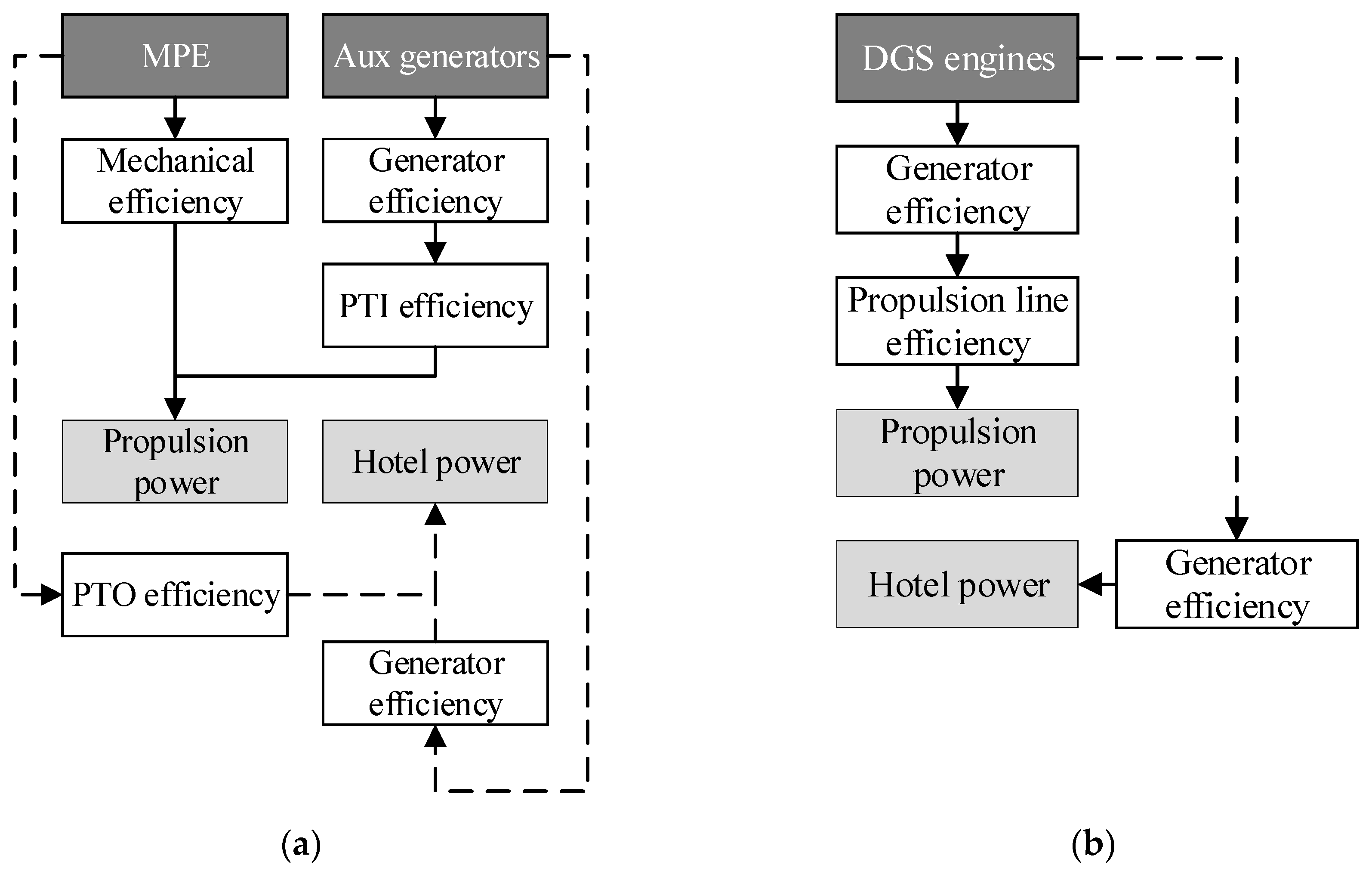
Figure 1 illustrates the power production alternatives and relative losses that were included as a basis for the study. In this case, a clear differentiation between engine types is displayed, however one single engine type could potentially be utilized either as a mechanical propulsion engine, or diesel-generator set (DGS) engine. In the case studies, both diesel-mechanical and diesel-electric propulsion concepts were investigated.
2.2. Optimization Approaches
2.2.1. General Approach
An optimization problem can be generally defined as the minimization of a given objective function, subject to a set of constraints. In this case, the optimization procedure aims at minimizing the total fuel consumption (
) of the ship, defined as the sum of the consumption of the MPEs (
), the auxiliary generators (
) and the DGS engines (
):
The calculation of the three aforementioned factors depends on the chosen optimization approach, and is presented in
Section 2.2.2 and
Section 2.2.3. The problem of optimizing the ship machinery system is also subject to a number of constraints. Equality constraints allow including in the problem physical principles, such as the conservation of energy (i.e., energy demand and energy generation must be equal at any time step). Inequality constraints allow including in the optimization problem the system’s operational limits, such as minimum and maximum engine loads.
Propulsion power can be produced in three ways: by MPEs, with auxiliary generators through PTI, or with DGS engines. Thus, the overall propulsion power in each sailing mode (
) is computed as follows:
where the set E consist of all the possible engines types that can be installed on the vessel,
e represents a specific engine type, which belongs to the considered set of possible engines, and
l represents a specific sailing mode.
,
and
stands for the power produced from a specific engine
e that is installed as a MPE, auxiliary, or DGS engine and that is supplied, either directly or indirectly (through the PTI), for propulsion purposes.
,
,
, and
represent the mechanical efficiency, generator efficiency, PTI efficiency, and propulsion line efficiency, respectively. The propulsion line efficiency groups all the losses connected with the use of DGS for propulsion purposes (i.e. it accounts for the losses in the electric motor, frequency converters and transformers).
Similarly, the propulsion system has to produce enough power for on-board electric consumers. This hotel power can be produced either by MPEs through PTO, by auxiliary generators, or by DGS engines. The hotel power production in each sailing mode
) is defined as follows:
where
,
and
stands for the power produced from a specific engine
e that is installed as a MPE, auxiliary, or DGS engine and that is supplied, either directly or indirectly (through the PTO), for hotel purposes; while
represents the PTO efficiency.
The maximum number of engines that can be installed on a ship is limited. The maximum number of installed engines (
Nmax) on a specific ship is generally set by the ship designers, based on the specific demands of the case under study.
Table 1 shows the maximum number of installed engines for each type in the two considered case studies.
The optimization routine was setup so select the propulsion mode through Equation (4):
where
m is a binary variable for choosing the mechanical propulsion and
d is a binary variable for choosing the diesel-electric propulsion configuration. Configurations featuring both mechanical and diesel-electric propulsion configurations were, therefore, not allowed.
The number of engines of type
e that could be installed in the ship (
) was constrained so to fulfill the constraint on the maximum number of installed engines:
where:
Similarly, for every sailing mode, the active engines were selected. The integer variables related to the engines installation (
) and those related to the active engines in each sailing mode (
) were connected by the following relations:
where
L is the set of all the ship sailing modes. This ensured that the number of active engines was always lower or equal to the amount of installed engines.
The active engines were allowed to produce power within the limits of feasible operational loads. For this, minimum and maximum loading of the engines were defined:
where
and
represent the minimum and maximum load limit for running engines, and were set to 0.15 and 0.90, respectively. These limits were set according to the internal expertise at Deltamarin.
denotes the maximum power output of the engine
e.
2.2.2. Linear Optimization
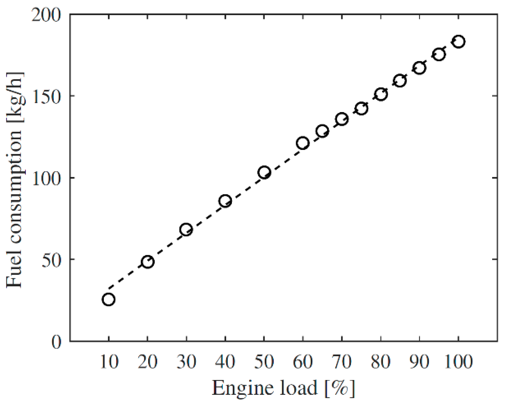
In order to carry out a mixed linear-integer optimization, the optimization domain needs to be linearized. To do so, the engine’s fuel consumption was approximated to be linearly correlated with the engine load, as shown in
Figure 2.
The linear approximation led to an average relative deviation by 2.55% compared to data. The maximum relative deviation was of 25.74%, and was found in correspondence to the lowest engine loads.
Given the proposed linear approximation, the fuel consumption (
FC) of each engine
e operated at the load
Ld was computed as:
where
and
are two regression constants defined for each engine.
The efficiency of the various components that constitute the machinery system was assumed to be constant with the load.
Table 2 shows the values assigned to the various efficiency factors.
In the MILP approach,
was defined as the sum of the consumption of the various engines in each sailing mode, where the fuel consumption of each engine was a linear function of its power output:
where
refers to the time spent in each sailing mode. Similarly, the consumption of the auxiliary generators was computed as:
Finally, the fuel consumption of the DEP system was computed as follows:
The MILP problem was implemented and solved by using GLPK [
19]. The relative mip gap tolerance was set to 0. The selected decision variables were the propulsion mode (mechanical or Diesel-electric), and the installed engines, while the optimization space is defined by the set of the possible engines to be installed (
E). The ship energy requirement is determined by the sum energy need in the various sailing modes, described in the set
L.
2.2.3. Non-Linear Optimization
Secondly, a non-linear model was developed in Matlab [
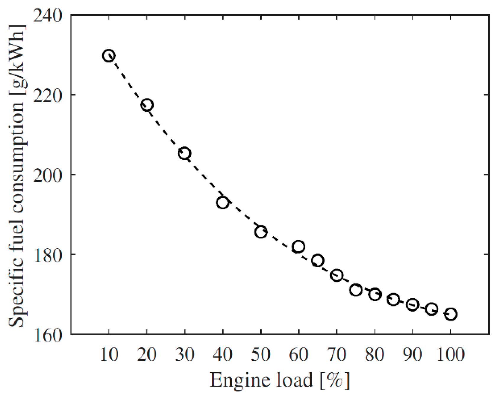
20]. The problem was solved using a two-step optimizer based on the genetic algorithm and fmincon (with multistart). The same rules and equations were utilized as in the linear model, while the specific fuel consumption (SFOC) data for the engines was approximated with the following non-linear form:
where the engine load is x and A, B, C and D are the regression coefficients calculated for each engine. In this case, the engine consumption was computed as specific fuel consumption (g/kWh) in order to capture the non-linearity of the engine efficiency (see
Figure 3).
The average and maximum relative deviations from the data were of 0.31% and 1.11%, respectively.
In the MINLP approach,
was defined as the sum of the consumption of the various engines in each sailing mode, where the fuel consumption of each engine was computed by multiplying the engine SFOC (computed through Equation (24)) to its power output:
Similarly, the consumption of the auxiliary generators was computed as:
Finally, the fuel consumption of the DGS engines was calculated as follows:
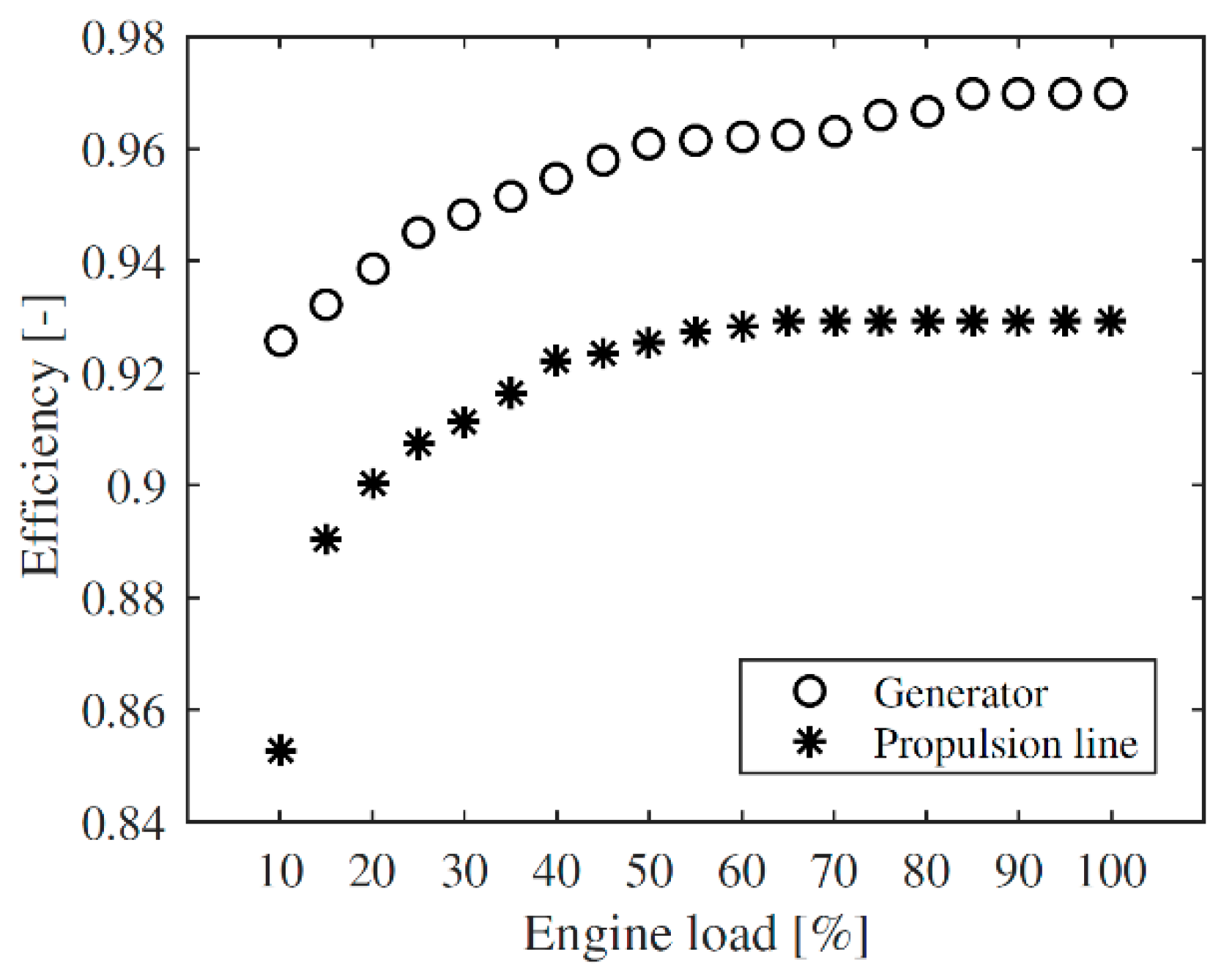
Efficiency curves for the electrical propulsion line and generator efficiency were provided by Deltamarin and included in the model, as illustrated in
Figure 4.
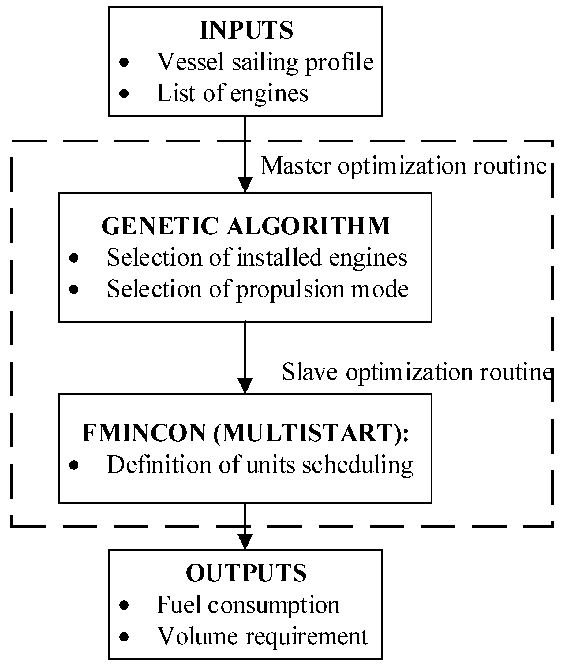
All the other performance parameters were kept constant as in the linear model. The overall optimization procedure was carried out according to the sketch shown in
Figure 5. The genetic algorithm was selected as it is suitable to handle problems that are highly non-linear and contain integer optimization variables. The optimization routines were carried out multiple times to ensure the validity of the attained maximums. The selected population size, maximum number of generations and function tolerance were of 500, 30 and 10
−6, respectively.
2.2.4. Multi-Objective Optimization
Lastly, a multi-objective optimization was setup. The optimization routine was the same as in the MINLP approach, with the addition of the overall volume of the installed engines as a second objective. The considered volume is that required for the engines themselves, but does not include the additional space required around the engines for maintenance tasks. This parameter was added as a way to identify a range of optimal solution to be screened according to the space requirements on board. The volume of the various engines was retrieved from the manufacturer’s product guides. The multi-objective optimizations were carried out using the genetic algorithm available in Matlab.
2.3. Case Studies
The study was carried out on two case studies, a cargo ship and a small cruise ship. The data for the cargo ship was provided by Deltamarin, while the operational profile and power requirements for the cruise ship were retrieved from the work of Baldi et al. [
21]. The typical day 3 was selected for this study, because it was the one characterized by the highest variations in the cruise operational modes.
Table 3 and
Table 4 detail the sailing profiles and the required propulsion/hotel power requirements for the cargo and the cruise ship, respectively.
In both cases, the heat requirements on board were not considered, and the engine selection was limited to the following Wärtsilä dual fuel engines (Wärtsilä, Helsinki, Finland) [
22]: 6L20DF, 8L20DF, 9L20DF, 6L34DF, 8L34DF, 9L34DF, 8V31DF and 10V31DF. The performance data for the various engines was attained through the manufacturer’s product guides and Deltamarin’s internal library, while the optimization was conducted by assuming liquefied natural gas as fuel for the ship.
4. Discussion
The results of the investigations suggest that MILP and MINLP approaches lead to the same optimized machinery systems for the two considered case studies. Similarly, the estimated annual fuel consumptions are comparable and differ by less than 1.0%. This indicates that the MILP is a suitable tool to address the problem considered, enabling fast and reliable solutions to be attained.
Looking at the unit scheduling that was attained by the two approaches, it emerges that the optimal solutions are characterized by an even loading of the propulsion engines (for the cruise ship case study), confirming the soundness of the common assumption to equally allocate the power requirement among the active propulsion engines. The general applicability of this assumption should, however, be further investigated.
In addition, the results indicate that the MILP is capable of correctly identifying the right engines to be operated in the various sailing modes. The discrepancies that emerge with the MINLP solution are due to a non-accurate treatment of the variation of the engines’ efficiency as a function of the load. A possible way to increase the accuracy of the MILP simulations is the use of piece-wise linearization of the engine’s performance. This would enable the inclusion of the non-linear engine performance in the linear framework.
The MINLP approach is characterized by significant possibilities for extension and refinement. In this study, the engine-specific fuel consumption, the generator and the propulsion line efficiencies were the only non-linear parameters accounted for. In practice, the selection of machinery system selection is a more complex task, which is not merely aiming at identifying the configuration leading to the lowest fuel consumption. The inclusion of other parameters, like the cost of the equipment, and constraints on the ship’s emission levels, would increase the significance of the results attainable through the MINLP approach, and enlighten the limitations of the MILP optimization.
The choice of the solvers is also an element to be considered. In this paper, either open-source tools (such as GLPK for linear optimization), or commonly used tools (such as Matlab’s built-in non-linear optimization tools) were selected in order to compare solvers that are commonly used in research papers dealing with the optimization of ship energy systems. Given the relatively low complexity of the problem addressed in this paper, we do not expect the choice solver to have a large impact on the solution. For more computationally intensive problems, however, it would be appropriate to consider state-of-the-art solvers, e.g., CPLEX. In addition, the use of state-of-the-art solvers would make it possible to draw conclusions regarding the computational efficiency of the two proposed approaches. In the present work, the use of the MILP approach led to substantially lower computational times compared to the use of the MINLP approach, but in order to estimate the computational gains attainable by linearizing the optimization space more accurately, the MILP and MINLP approaches need to be compared based on state-of-the-art solvers.
It should also be considered that the sailing modes of a ship could be subjected to changes over time. This could be caused by factors such as slow steaming, or by a variation of the specific route of a vessel. These variations are expected to affect in a similar way the performance of the machinery systems attained by the MILP and MINLP approaches, especially because the machinery systems attained by the optimization procedures featured the same installed engines. Therefore, such changes of the sailing mode of the ship are not expected to affect significantly the conclusions regarding the optimization approaches addressed in the paper.
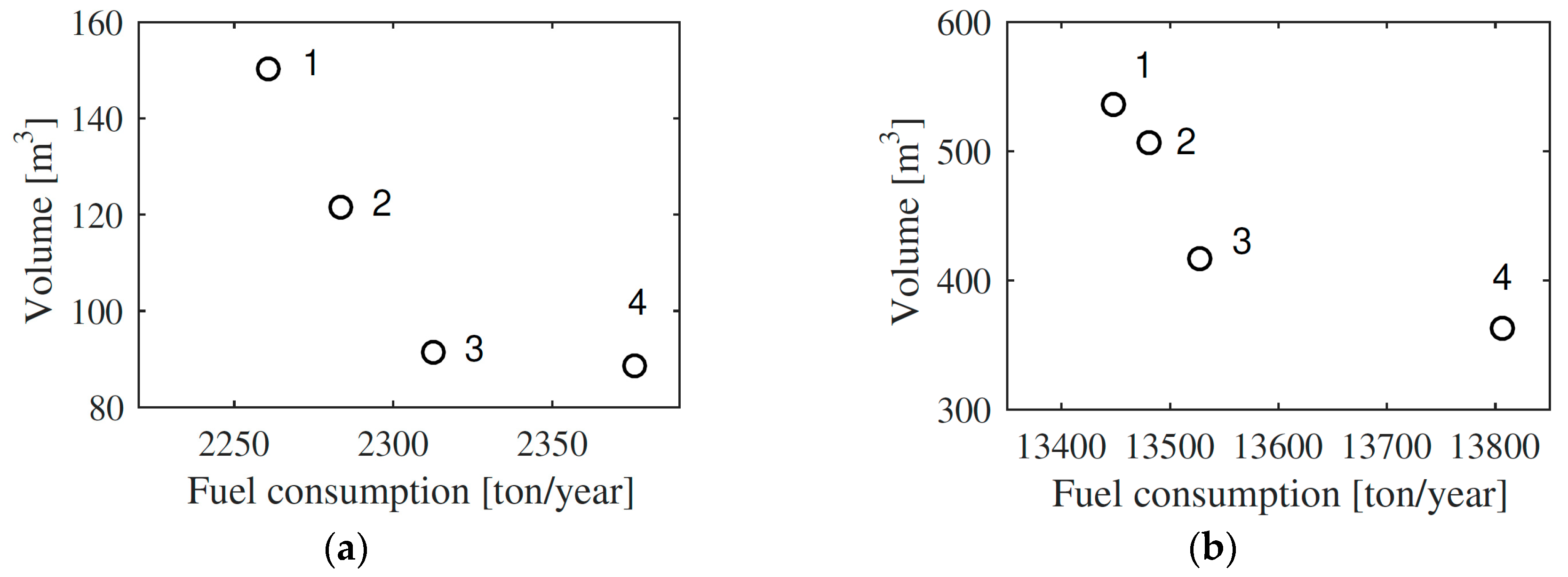
The results of the multi-objective optimizations give a clear indication of how designing the machinery system looking only at the overall fuel consumption does not yield the best solution. As discussed in
Section 3.3, suboptimal solutions result in a substantial reduction of the space required for the machinery system, with minor increases in the overall fuel consumption. Therefore, it is essential to make these trade-off considerations during the ship design phases, and, possibly, to include also economic aspects in the evaluations. In this regard, we believe that the use of multi-objective optimization routines should be considered the preferable tool for designing ships’ machinery systems.
All the simulations indicate that the lowest fuel consumption could be attained by implementing a mechanical propulsion system. However, the diesel-electric propulsion layout, despite the lower overall efficiency, has other advantages, such as more compact layout, better maneuvering and dynamic performance. Moreover, the use of a diesel-electric approach generally leads to a lower total installed engine capacity, which emerges as an advantage when minimizing the cost, but not the fuel consumption.
The entire hull shape may change as a function of the selected propulsion unit type and, therefore, for certain ship types it might be practical to consider separately the diesel-mechanical and diesel-electric propulsion concepts, and choose the optimum within these separate concepts.
In general, this study disregarded several aspects to be considered when designing machinery systems. For instance, only a small selection of four-stroke, dual-fuel engines with fixed speed was included in the study. Including more engine alternatives, different fuel options and other types of power source would be required for a more holistic machinery study. Additionally, further details for the machinery should be added, such as possible exhaust gas-cleaning methods and ship heat requirements on board, coupled with an estimation of the prospects for waste heat recovery. This would enable designing the overall ship energy system, including recovery boilers and, potentially, waste-to-power recovery systems (e.g., organic Rankine cycle power systems [
23]). In addition, the study only focused on operational expenses (fuel consumption), while a more comprehensive analysis should also include capital expenses, although it is well known that these are more difficult to estimate with good accuracy.
Lastly, this work focused only on the optimization of the operation and design of the machinery system of a ship. Estimations of the overall environmental impact of a ship could be carried out by implementing life-cycle assessment calculations, or by calculating the overall carbon footprint of a specific ship.


