1. Introduction
Offshore wind power is rapidly developing toward large-capacity units and far-sea applications, and foundations such as monopiles, jackets, and caissons have become the dominant support forms for offshore wind turbines (OWTs). However, OWT support structures are subjected to complex combined environmental loads including wind, waves, currents, sea ice, earthquakes, and long-term cyclic actions from rotor rotation, while the strong fluid–structure–seabed interaction and geological conditions further aggravate the complexity of structural mechanical responses. Xie et al. [
1] reviewed the main types and dynamic characteristics of fixed and floating OWT foundations with Chinese cases, summarized key issues such as pile–soil interaction and mooring systems, and proposed design optimization insights to enhance the safety and reliability of OWTs. Zhou et al. [
2] conducted full-scale hydrodynamic numerical simulations on OWT jacket foundations under combined wave–current actions, providing valuable case references and technical support for wave force simulation of far-sea jacket foundations. Thomas et al. [
3] numerically investigated the flow dynamics around monopile and tripod OWT foundations under pseudo-periodic wave conditions, and clarified that wind speed within the studied range barely influences pressure distributions or strain rates but affects skin friction coefficients.
The dynamic characteristics (e.g., natural frequency, damping, modal parameters) and resonance mechanism are the core theoretical basis for avoiding resonance and ensuring structural safety of OWTs. Tian et al. [
4] conducted scaled model tests in sand to investigate the natural frequency of monopile-supported OWTs considering soil–monopile interaction, and revealed that soil nonlinearity degrades frequency while cyclic loading increases it. Li et al. [
5] established a high-efficiency closed-form solution for the overall natural frequency of OWTs considering pile–soil interaction, and verifications show that the solution is convenient and rapid. Xi et al. [
6] developed an automated operational modal analysis and data-driven method to identify damping sources for OWTs, supporting reliable structural design. Li et al. [
7] derived an explicit multi-mode aerodynamic damping solution for monopile-supported OWTs, and found that the first-mode aerodynamic damping is far higher than that of the second and third modes with negative damping in the third S-S mode implying potential instability. Ju [
8] proposed an analysis method for OWT structures and wave loads using Wave Participation Factor ratios (WPFs) and clarified the distinct resonance characteristics of fixed and floating OWTs. Yang et al. [
9] demonstrated that higher-harmonic wave responses are prominent and far exceed linear estimates under combined wind–wave loads, and emphasized the non-negligible higher-harmonic effects for OWT safety design. Xi et al. [
10] investigated the directionality effect of a 10 MW monopile-supported OWT and systematically revealed its significant structural anisotropy in modal frequencies, aerodynamic damping and seismic responses. Zhang et al. [
11] carried out model tests on OWT dynamic responses under asymmetric wind–wave loads, verified their significant influence, and determined the most unfavorable condition.
In view of the difficulties in coupled dynamic analysis and multi-scale testing of OWTs, scholars have carried out extensive research on numerical models, hybrid simulation and experimental methods. Liu et al. [
12] found that a coupled aerodynamic–hydrodynamic–soil numerical model can accurately predict offshore wind turbine dynamic responses and that nonlinear wave hydrodynamics and wave-induced high-frequency dynamics pose critical safety risks that should be incorporated into turbine design. Al-Subaihawi et al. [
13] extended real-time hybrid simulation to monopile-supported OWTs, and established a validated coupled framework that can realistically capture soil–foundation nonlinearity and coupled dynamic responses in real time. Cao et al. [
14] demonstrated that significant excess pore pressure accumulates under wind–wave loads and 3D seawater modeling produces more intense dynamic responses, and clarified that soil damping relies on actual soil stress and operational conditions. Meng et al. [
15] proposed an efficient hypoplastic macroelement model for large-diameter OWT monopiles in sand. Guo et al. [
16] demonstrated that loading/operating states significantly affect strain of OWT, waves amplify foundation top strain, aerodynamic loads dominate at high intensities, and fluid–structure coupling is indispensable. Cheng et al. [
17] investigated the evolution of natural frequency and accumulated rotation of three OWT foundations under soil stiffness degradation, and proved that increasing pile or bucket diameter is the most effective optimization measure with equal steel consumption. Malik et al. [
18] investigated the lateral load-bearing behavior of OWT caisson foundations, and provided a theoretical basis for caisson foundation design. Zhang et al. [
19] found that scour protection slightly raises the first natural frequency and reduces seismic responses, while seismic responses are more sensitive to scour protection length than elastic modulus.
Long-term performance degradation, multi-hazard damage and safety assessment are key issues restricting the service safety and life of OWTs. Liang et al. [
20] found that support stiffness and damping are negatively correlated with the fatigue damage of monopile-supported OWTs, and their rapid reduction can cause excessive fatigue damage over the service life. Zhang et al. [
21] demonstrated that coupled corrosion–fatigue damage alters the failure mode of monopile OWTs from global bending to local buckling and greatly raises the collapse probability under multi-hazard events, which improves the accuracy of failure identification and vulnerability analysis. Sui et al. [
22] investigated the dynamic response of a 10 MW jacket-type OWT under combined wind and sea ice loads. Wu et al. [
23] reported that TMDs can mitigate ice-induced vibrations of OWTs; a single TMD controls first-mode displacement, multiple TMDs are needed for higher-order acceleration, and increasing TMD mass enhances control robustness. Yang et al. [
24] reviewed the SHM and damage identification methods for OWT support structures, analyzed their challenges and future trends, and provided guidance for structural monitoring and fault diagnosis. Dong et al. [
25] proposed a projection-pursuit- and extension-cloud-model-based safety evaluation method for OWTs, verified its feasibility via numerical and monitored data, and validated its engineering value for the intelligent maintenance of offshore wind farms.
To suppress excessive vibrations induced by environmental loads and improve structural robustness, researchers have developed a variety of vibration control technologies for OWTs. Liang et al. [
26] developed a novel high-damping wall-type viscoelastic damper (HVED) for OWT tower vibration mitigation under wind–wave loads, and verified that it can significantly reduce structural dynamic responses. Kim et al. [
27] analyzed the vibration control performance of a variable-natural-frequency damper for monopile-type OWTs under cyclic environmental loads; their results show that the peak tower-top displacement can be reduced significantly.
However, there are still gaps that need to be further investigated: Firstly, most existing numerical studies mainly focus on the dynamic response of OWTs under rated operating conditions, with only brief description of cut-out shutdown conditions, lacking response evolution under extreme cut-out states. Secondly, existing studies mostly take F-A response as the core analysis object; therefore, studies on the differential characteristics and formation mechanism between F-A and S-S directional responses under full operating conditions are still needed. Thirdly, the evolution of structural dynamic response and foundation reaction under wind speeds exceeding the cut-out threshold is rarely discussed, which cannot provide sufficient data support for the extreme load investigation of OWTs.
To further supplement the above insufficiently studied contents and help researchers deepen the understanding of monopile OWT wind–wave coupled dynamic response under full operating conditions, this work conducts a fully coupled numerical analysis of the NREL 5MW monopile OWT using FAST software, covering cut-in, rated, cut-out and over-cut-out extreme conditions. The core content of this study can be summarized as follows: (1) Systematically compare the differential characteristics of F-A and S-S directional dynamic responses under three typical operating conditions to reveal the correlation between aerodynamic damping, modal participation and response amplitude; (2) Quantitatively analyze the evolution of structural dynamic response and foundation reaction under over-cut-out extreme wind speeds; (3) Verify the dynamic transmission mechanism between aerodynamic loads, tower dynamic response and foundation reaction under different operating conditions.
2. Modeling of the System
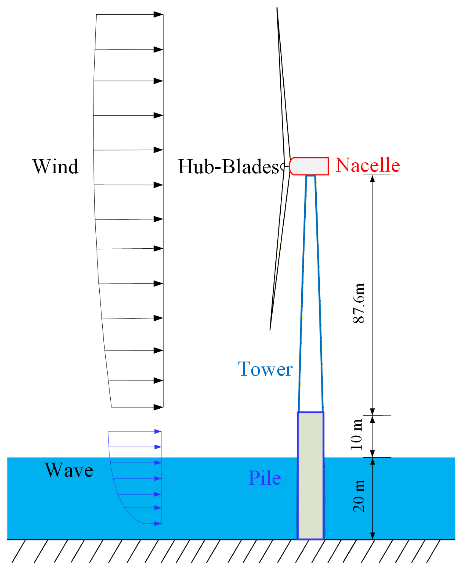
This study adopts the 5MW OWT with OC3 monopile tower (see
Figure 1) developed by the National Renewable Energy Laboratory (NREL), with detailed parameters available in Ref. [
28]. The NREL 5-MW turbine utilizes an integrated variable-speed and variable-pitch servo control scheme that categorizes its operating process into three distinct states: cut-in, rated, and shutdown. When the wind speed exceeds the cut-in threshold, the rotor–nacelle assembly (RNA) operates with variable-speed control activated, and the rotor speed is continuously regulated to maximize wind energy capture; when the wind speed rises above the rated value, the rotor maintains an approximately constant rated rotational speed; and once the wind speed surpasses the cut-out threshold, the wind turbine shuts down completely.
In this study, a mean wind model with a power-law wind profile is employed to account for the effect of wind shear on the aerodynamic loads of the rotor, while the Kaimal spectrum is utilized to compute the turbulent component of the wind velocity field. In accordance with IEC 61400-1 [
29], the roughness exponent is set to 0.14, and the turbulent wind field is defined using Class B turbulence characteristics and the Normal Turbulence Model (NTM) specified by the standard. The OWT targets typical shallow-water offshore wind farms in the central Taiwan Strait, matching the OC3 monopile foundation of the adopted NREL 5MW OWT. All simulated wind and wave parameters are derived from the wind–wave relationship established by Xu et al. [
30] based on field-measured data in the target sea area.
Moreover, the simulation time step is set to 0.005 s, the total simulation duration is 1200 s with the first 600 s transient zone excluded, and the effective analysis duration is 600 s. The generalized-alpha solver in OpenFAST is adopted, with numerical stability guaranteed by strictly satisfying the CFL condition. The monopile is discretized into 20 vertical beam elements, and the pile–soil interaction is simulated based on API standard curves.
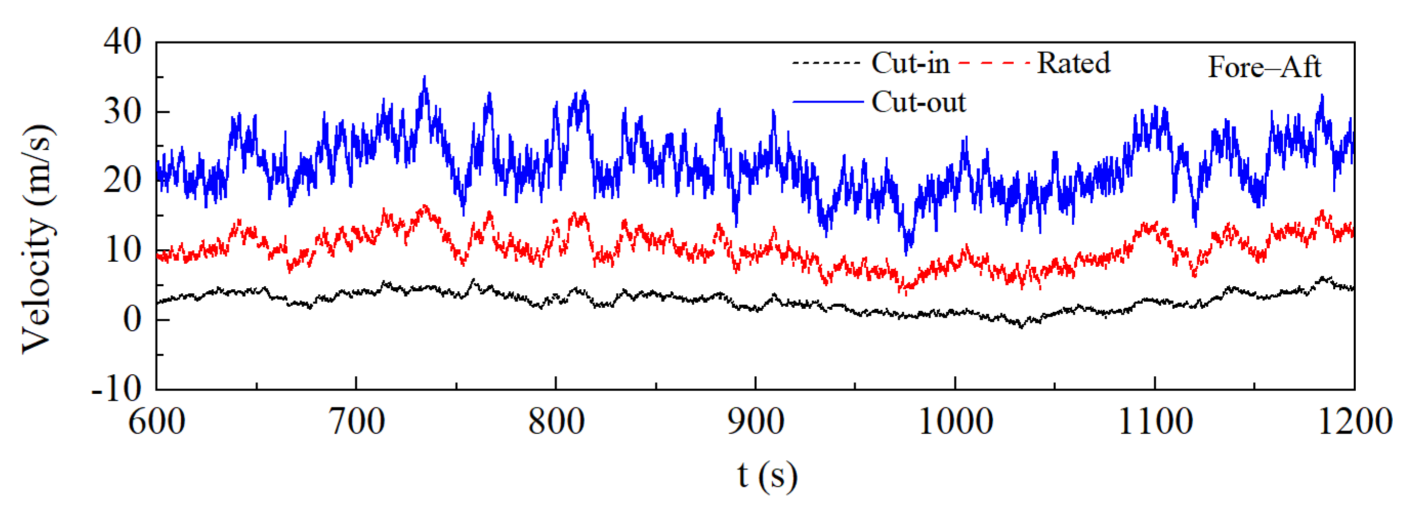
The spatial turbulent wind field over the rotor plane is simulated using TurbSim TurbSim v1.06 with the hub as the center and a wind velocity grid covering the full rotor-swept area, which consists of 31 × 31 wind velocity points corresponding to a coverage area of 145 m × 145 m. The wind speeds at cut-in, rated and cut-out conditions obtained from the simulation are presented in
Figure 2, and the wind and wave load parameters under various conditions can be found in
Table 1.
It should be noted that, for the high turbulence induced by the uncertain cut-out process beyond the maximum cut-out wind speed, the turbulent wind field is generated using the IEC 61400-1 standard Kaimal turbulence model consistent with the NREL 5-MW OWT design specifications. Moreover, turbulence intensity is normalized to the 10 min average hub-height wind speed, with the effects of vertical wind shear and turbulence integral scale considered in order to constrain turbulence uncertainty during the cut-out process.
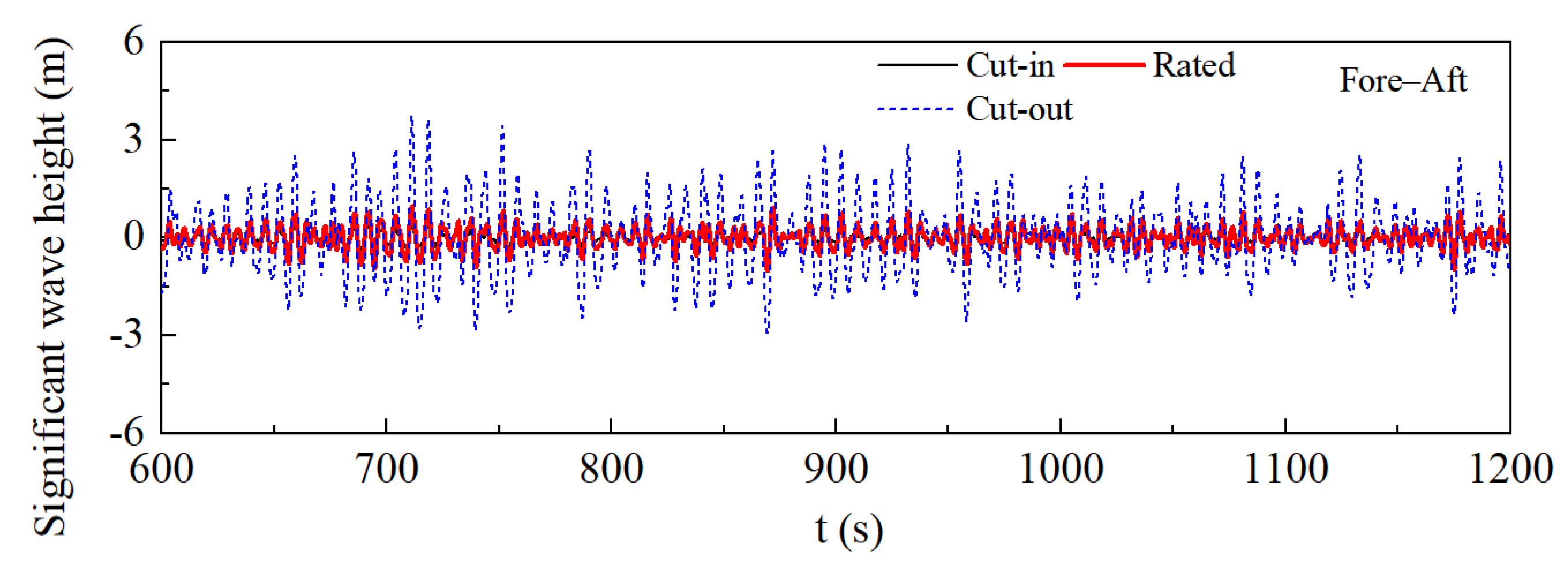
In this study, the JONSWAP wave spectrum is adopted to simulate the wave conditions, and the Morison equation is employed to calculate the wave loads acting on the monopile foundation [
31]. The simulated waves are illustrated in
Figure 3.
To validate the model parameters, the tower frequencies of the NREL 5-MW OWT in both F-A and S-S directions are verified to ensure that FAST simulated the structure accurately (see
Table 2). It can be observed that FAST precisely captures the dynamic characteristics of the NREL 5-MW OWT.
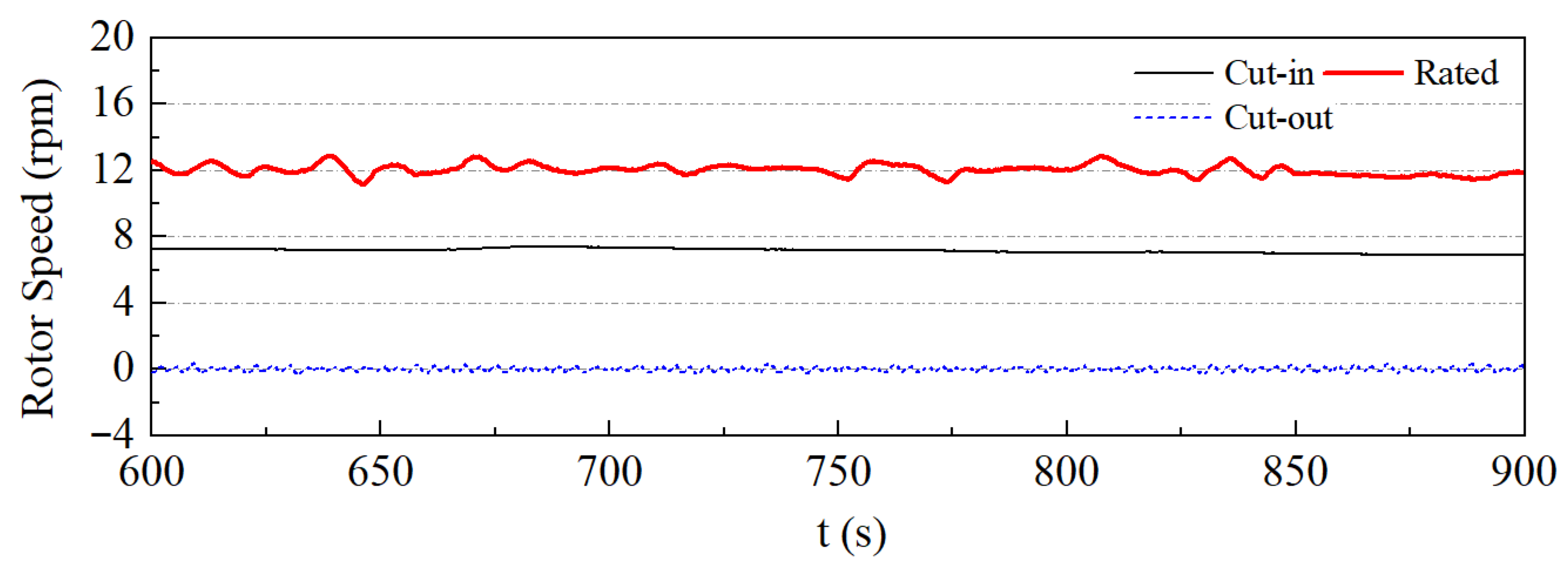
Meanwhile, since different operating conditions correspond to distinct rotor speeds, the rotor speed results are presented in
Figure 4. According to the design specifications of the NREL 5-MW OWT, the rotor speeds at cut-in, rated, and cut-out conditions are 6.9 rpm, 12.1 rpm, and 0 rpm, respectively [
31]. The results demonstrate that the numerical simulations in this study agree well with the actual model parameters, thereby ensuring the accuracy and reliability of the present results.
It should be noted that this study does not consider the effect of marine current acting on the submerged section of the monopile. This simplification is set to focus on the core wind–wave coupling mechanism of the monopile OWT’s dynamic response, avoiding the interference of multi-factor coupling. Compared with the dominant wind–wave coupling loads, the magnitude of marine-current-induced load is significantly smaller, and its effect is not prominent for the shallow-water monopile OWT targeted in this study.
3. Structural Dynamic Behavior of the OWT
The total simulation duration is 1200 s for each working condition, while the first 600 s is excluded as the numerical transient zone and the remaining 600 s is taken as the effective stationary analysis interval; therefore, the time-history curves use the full data of this effective interval, and envelope curves of loads and structural responses are derived from the absolute extreme values within the effective duration.
3.1. Aerodynamic Loads
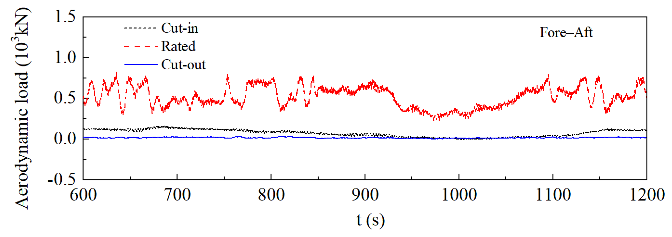
Figure 5 shows the total aerodynamic load time-history applied on the rotor of OWT along the F-A direction under three typical operating conditions: cut-in, rated, and cut-out. Notably, load amplitude and dynamic fluctuation are most pronounced under rated conditions, with the load time-history varying between 0.25 × 10
3 kN and 0.75 × 10
3 kN and exhibiting quasi-periodic fluctuations associated with the blade rotation frequency. Aerodynamic loads under cut-in are substantially lower. Under cut-out, loads approach zero with a fluctuation amplitude 0.03 × 10
3 kN.
These differences in load characteristics are attributed to the wind speed conditions, rotor operating status, and aerodynamic load mechanism of the OWT. The turbine operates at full power for rated conditions. Combined atmospheric turbulence at high wind speeds, tower shadow effects from blade rotation, and aeroelastic coupling result in aerodynamic loads characterized by significant quasi-periodic fluctuations superimposed with random disturbances, which is why this condition serves as the core basis for fatigue life design of structures such as the tower and blades. Cut-in corresponds to the low-wind-speed startup phase, where the rotor has just started rotating. With a small flow angle of attack, low turbulence intensity, and weak aerodynamic excitation, both load levels and fluctuation amplitudes are low. Under cut-out, the turbine triggers shutdown protection and the rotor stops active rotation and is only subjected to weak airflow disturbance and aerodynamic damping. Significantly reduced aerodynamic excitation results in near-zero loads and stable dynamic responses.
It can be found that the F-A aerodynamic thrust under rated condition is 25 times the average amplitude under cut-out condition, which is the direct quantitative cause of the 3.8-fold difference in tower-top F-A displacement between the two working conditions (0.689 m under rated conditions for rated but only 0.180 m for cut-out condition).
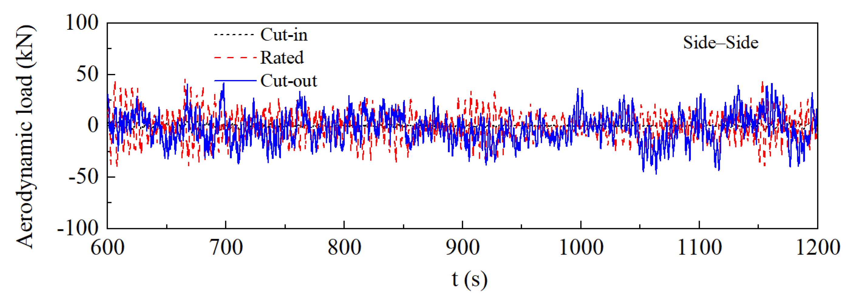
Figure 6 shows the total aerodynamic load time-history response of the wind turbine rotor along the S-S direction under three typical operating conditions: cut-in, rated, and cut-out. It can be found that loads varied around zero, with significantly variations for rated conditions, and slightly smaller variations for the cut-in and cut-out conditions.
These results are attributed to the unique aerodynamic load mechanism of OWT: the lateral aerodynamic loads are mainly caused by the combined effects of lateral components of atmospheric turbulence, blade-induced aerodynamic loads and aeroelastic effects. For rated conditions, the turbine operates at the rated tip-speed ratio, and the synergistic effect of lateral turbulence and aerodynamic asymmetry from blades accelerates the oscillation of the dynamic load. For the cut-in condition, the OWT is in the low-wind-speed startup phase, and load variation is less pronounced. For the cut-out condition, the overall amplitude is weaker than other conditions since the rotor ceases active rotation.
Although the amplitude of S-S aerodynamic load under the rated condition is slightly higher than that under cut-out condition, the aerodynamic damping provided by rotor rotation under rated condition is 8.3 times that under cut-out condition, which offsets the excitation effect of S-S load. This is the core reason why the maximum S-S structural response occurs under the cut-out condition rather than rated condition.
3.2. Deformation Characteristics
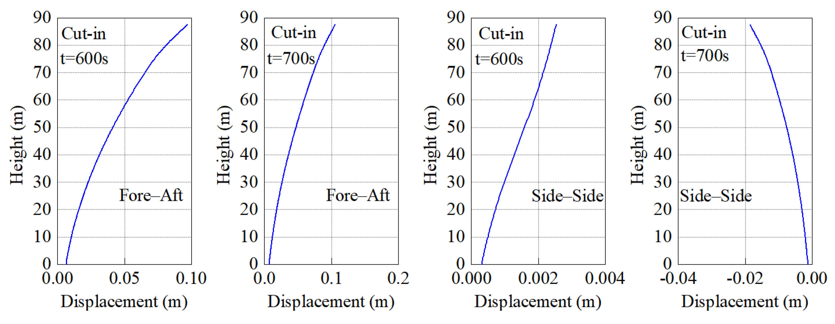
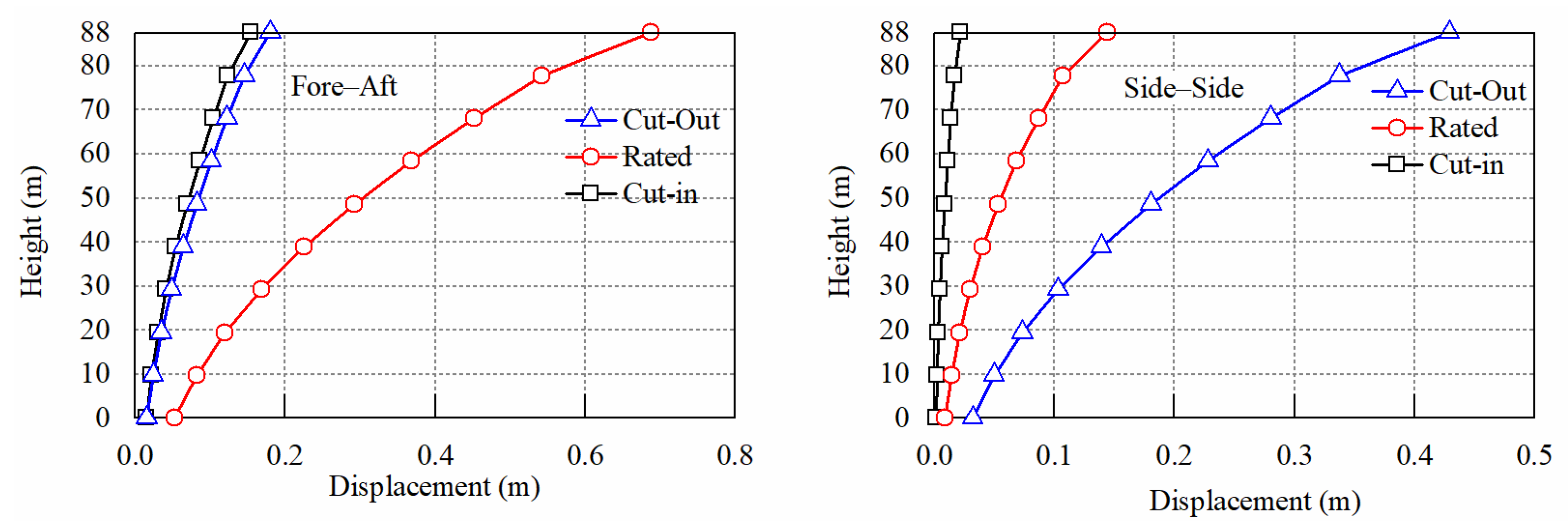
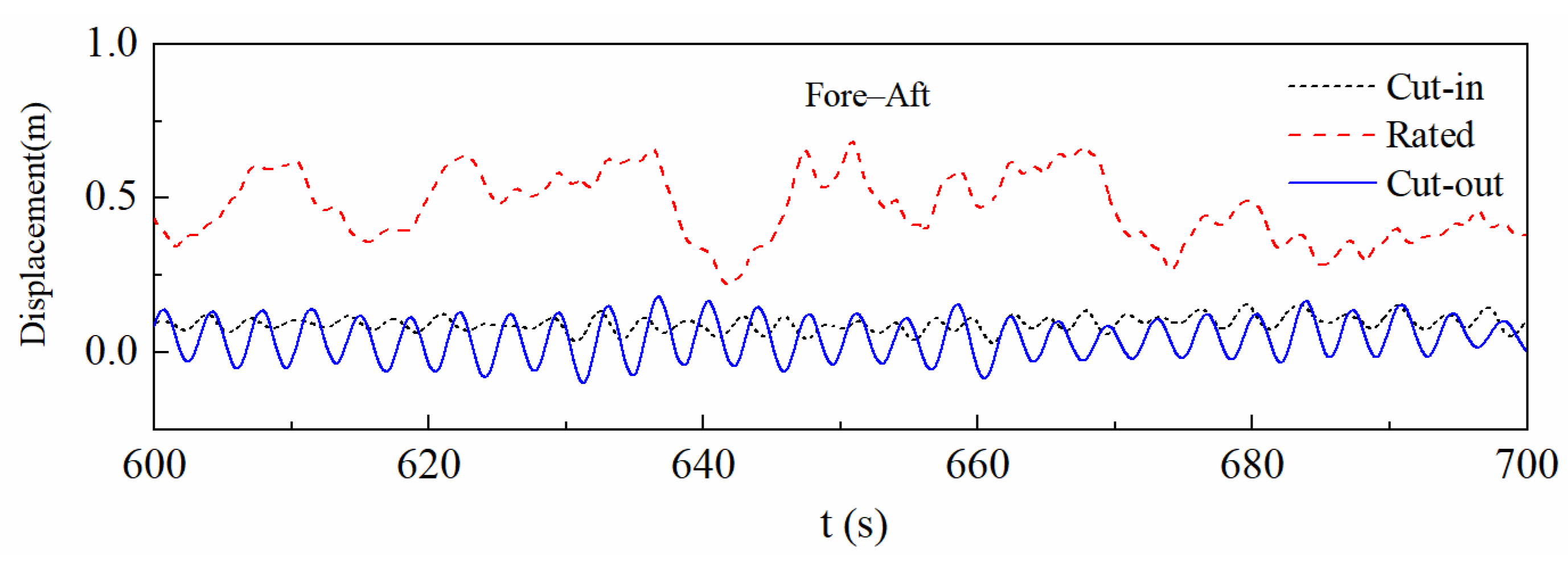
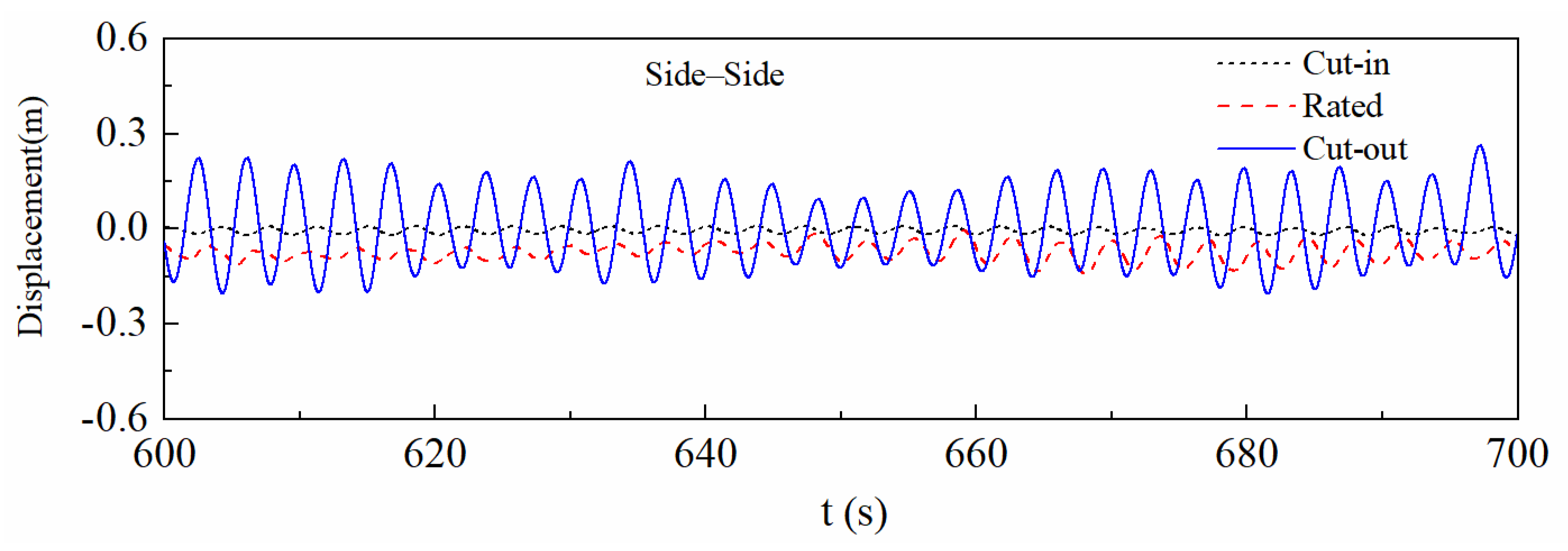
Figure 7,
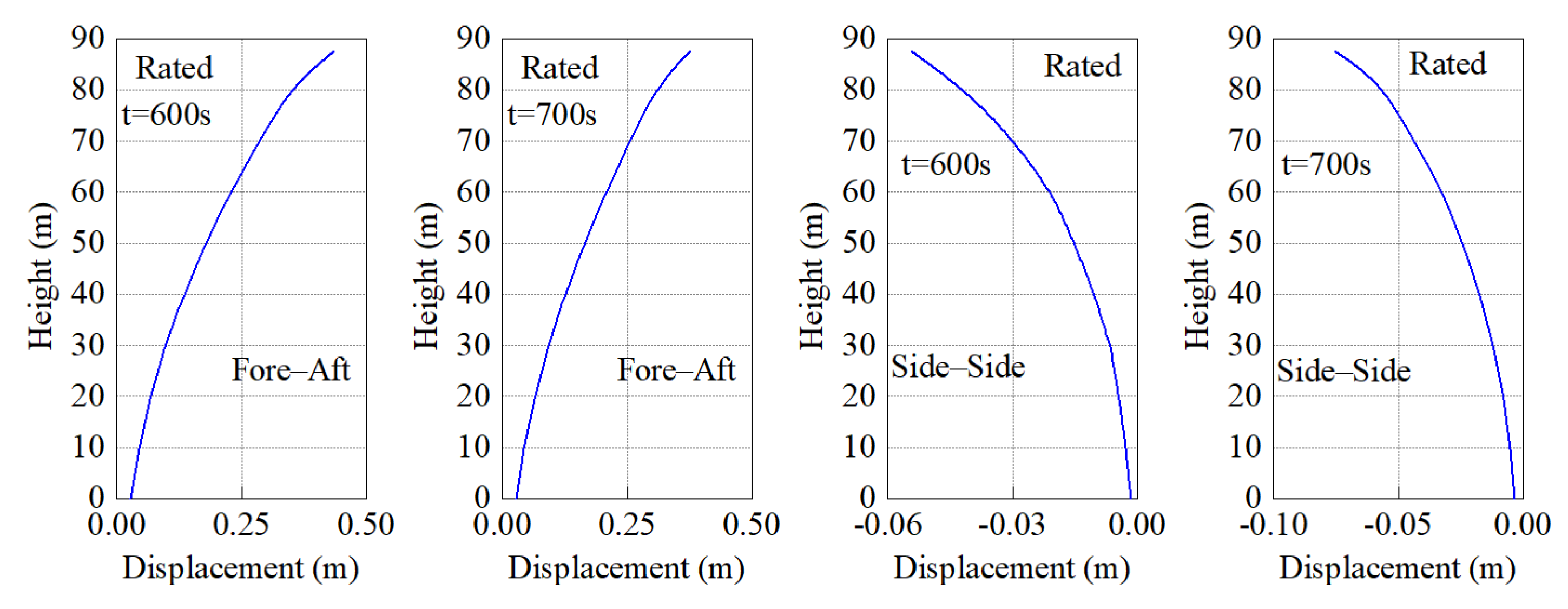
Figure 8 and
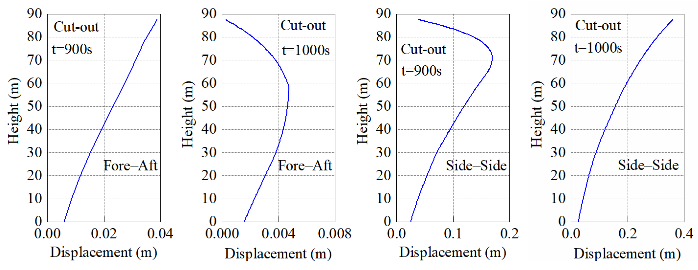
Figure 9 present the deformation characteristics of the tower under cut-in, rated, and cut-out conditions. For cut-in and rated conditions, the displacement exhibits a smooth quasi-linear growth trend in both F-A and S-S directions, and is similar to the typical deformation feature of the first-order bending mode of cantilever structures. In other words, the maximum displacement can be found on the top, and there are no obvious inflection points of higher-order modes. The results indicate that tower deformation is dominated by the first-order bending mode under these two conditions. However, for the displacement along the height in the F-A direction (t = 1000 s) and S-S direction (t = 900 s, t = 1000 s), the curves exhibit obvious inflection points under cut-out conditions.
This suggests that tower deformation under cut-out conditions is not solely dominated by the first-order mode, with significant participation of higher-order bending modes based on the validated modal results of the industry-recognized NREL 5-MW OWT benchmark model [
31].
The differences in the mode participation characteristics stem from the coupling effect of aerodynamic load excitation characteristics and structural damping status. Under cut-in and rated conditions, the wind turbine operates stably: the axial aerodynamic thrust generated by rotor rotation and lateral turbulence disturbances are mainly low-frequency excitations, whose frequency is close to the first-order natural frequency of the tower. Meanwhile, the rotor aerodynamic damping is strong, which can help to suppress the excitation of higher-order modes; as a result, deformation is dominated by the first-order bending mode. Under cut-out conditions, the wind turbine triggers shutdown protection, and the rotor ceases active rotation; as a result, the aerodynamic damping is significantly reduced. The main vibration load applied on the tower is the wind load, which acts on the tower surface. The participation of higher-order modes of the tower is due to the presence of fluctuating wind and its variation along the tower height.
3.3. Displacement Response
Figure 10 shows the displacement envelope curves of the tower along the F-A and S-S directions under cut-in, rated, and cut-out conditions. As observed, the F-A direction exhibits the largest displacement envelope amplitude under rated conditions, with the tower-top displacement reaching 0.689 m; the F-A displacement envelope amplitudes under cut-in and cut-out conditions are comparable, with the top displacement being only 0.155 m and 0.180 m respectively, significantly smaller than that under rated conditions.
The S-S direction presents a different amplitude pattern: the displacement envelope amplitude is the largest under cut-out conditions (top displacement is 0.429 m), followed by rated conditions (top displacement is 0.144 m), and is the smallest under cut-in conditions (top displacement is only 0.0218 m).
In terms of deformation characteristics, the displacement monotonically increases with tower height under all conditions, aligning with the bending deformation characteristics of cantilever structures. The differences in the morphology of envelope curves between different conditions and directions further reflect the disparities in mode participation characteristics; for instance, the large S-S displacement envelope under cut-out conditions indicates a significant contribution from higher-order modes.
The differences in the tower’s displacement envelope characteristics are because of the coupling effect of aerodynamic load excitation characteristics and structural damping status. F-A displacement is mainly dominated by the rotor’s axial aerodynamic thrust. The turbine operates at full power, and the coupling of high wind speeds with the rated tip-speed ratio maximizes the axial thrust under rated conditions; therefore, the deformation is governed by the first-order bending mode. But for cut-in and cut-out conditions, the turbine is in low-wind-speed startup and shutdown states, respectively, where axial aerodynamic excitation is significantly weakened, resulting in smaller displacement envelope amplitudes (see
Figure 11).
S-S displacement is jointly driven by lateral turbulence and rotational aerodynamic effects: Under cut-out conditions, the rotor ceases rotation, leading to a substantial reduction in aerodynamic damping. High-frequency components of atmospheric turbulence and shutdown transient loads can excite the tower’s higher-order bending modes, causing a marked increase in S-S displacement envelope amplitude. Under rated conditions, the aerodynamic damping induced by rotor rotation is strong, with lateral deformation dominated solely by the first-order mode, resulting in a moderate displacement envelope amplitude. Under cut-in conditions, low wind speeds lead to weak lateral turbulence intensity and insufficient lateral excitation, thus giving rise to the smallest displacement envelope amplitude (see
Figure 12).
3.4. Acceleration Response
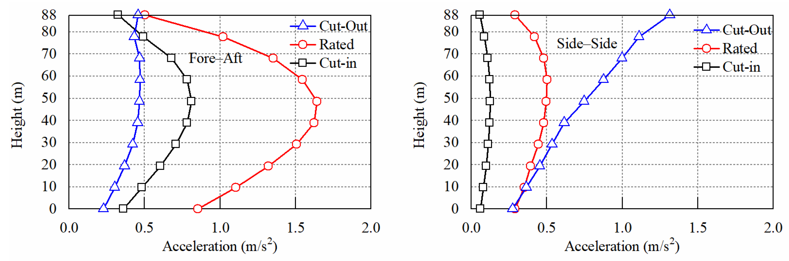
Figure 13 shows the acceleration envelope curves of the tower along the F-A and S-S directions under cut-in, rated, and cut-out conditions. In the F-A direction, the acceleration amplitude under rated conditions is significantly higher than those under other conditions: the peak acceleration in the middle–lower section approaches 1.643 m/s
2 (at height is 48.7 m), while the top acceleration decreases to 0.503 m/s
2. The acceleration response under cut-in conditions exhibits a similar trend to the rated condition, ranging from 0.324 m/s
2 (at the tower top) to 0.811 m/s
2 (at a height of 48.7 m). Cut-out conditions yield the smallest acceleration amplitude, with only 0.227 m/s
2 to 0.455 m/s
2 at the tower top.
In the S-S direction, the largest acceleration amplitude occurs under cut-out conditions, monotonically increasing with height, with the top acceleration approaching 1.32 m/s2, as the feathered shut-down rotor no longer captures wind energy, leaving the OWT loads dominated by wind loads that rise significantly along the tower via vertical wind shear; meanwhile, weak S-S turbulence makes the response purely controlled by the first-order bending mode with amplitude increasing with height, further amplifying this trend. For rated conditions, the acceleration peaks in the middle–lower section and slightly decreases at the top. Cut-in conditions have the smallest acceleration amplitude, with only 0.0567 m/s2 at the top. Comparing the two directions, the peak acceleration in the F-A direction is concentrated in the middle–lower section, while that in the S-S direction is focused at the top, reflecting the differences in mode participation between the two directions.
The differences in the acceleration envelope characteristics stem from the coupling effect of aerodynamic load excitation characteristics and structural modal responses.
F-A acceleration is mainly dominated by the dynamic variation in axial aerodynamic thrust and the first-order bending mode: Under rated conditions, the turbine operates at full power, and high-amplitude quasi-periodic aerodynamic thrust excites the tower’s first-order bending mode. Since the peak bending moment of the first-order mode resides in the middle–lower section, the peak of the acceleration envelope is concentrated in this range. The cut-in condition corresponds to the low-wind-speed startup phase, where transient aerodynamic excitation induces acceleration to increase with height. Under cut-out conditions, the rotor shuts down, and axial aerodynamic excitation is significantly attenuated, leaving only weak residual disturbances, thus yielding the smallest acceleration amplitude.
S-S acceleration is jointly driven by lateral turbulence and higher-order bending modes: Under cut-out conditions, rotor shutdown leads to a marked reduction in aerodynamic damping. High-frequency components of atmospheric turbulence and shutdown transient loads excite higher-order bending modes, and the peak deformation of these higher-order modes is located at the tower top. Consequently, the S-S acceleration envelope increases monotonically with height and exhibits the largest amplitude. Under rated conditions, strong aerodynamic damping generated by rotor rotation restricts lateral response to the first-order mode alone; with the first-order mode’s peak bending moment in the middle–lower section, the acceleration peak is concentrated there. Under cut-in conditions, low wind speeds result in weak lateral turbulence intensity and insufficient lateral excitation, leading to the smallest S-S acceleration amplitude.
3.5. Base Reactions
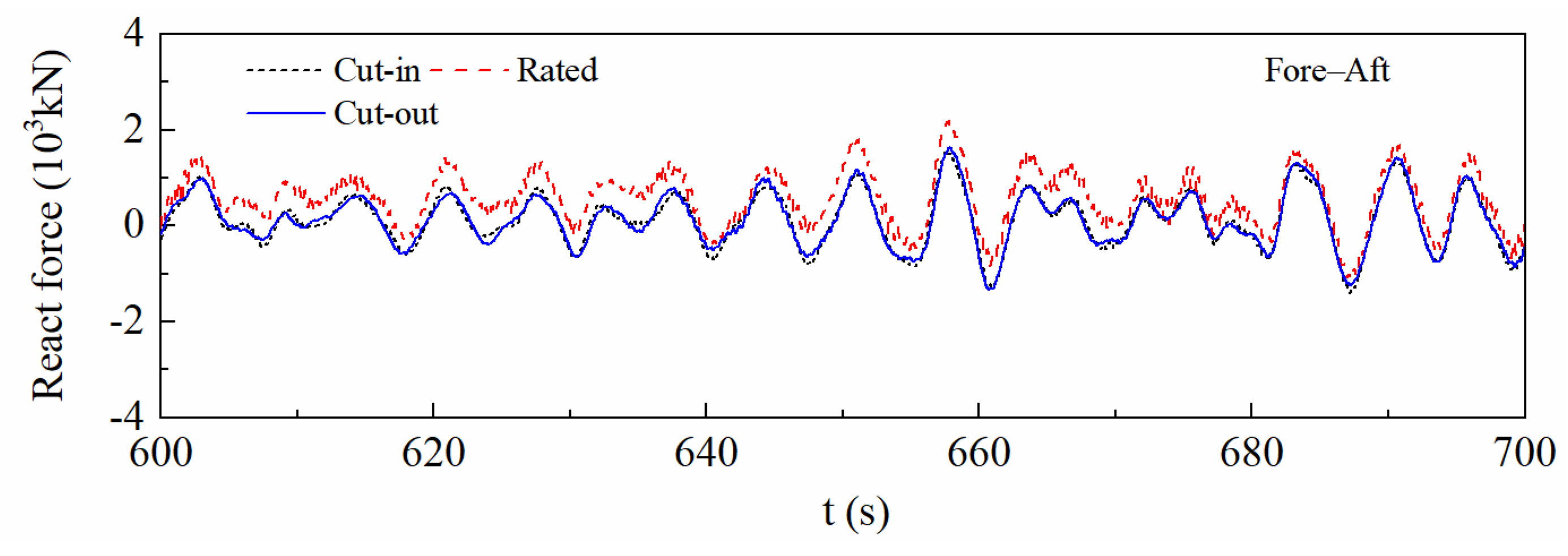
Figure 14 and
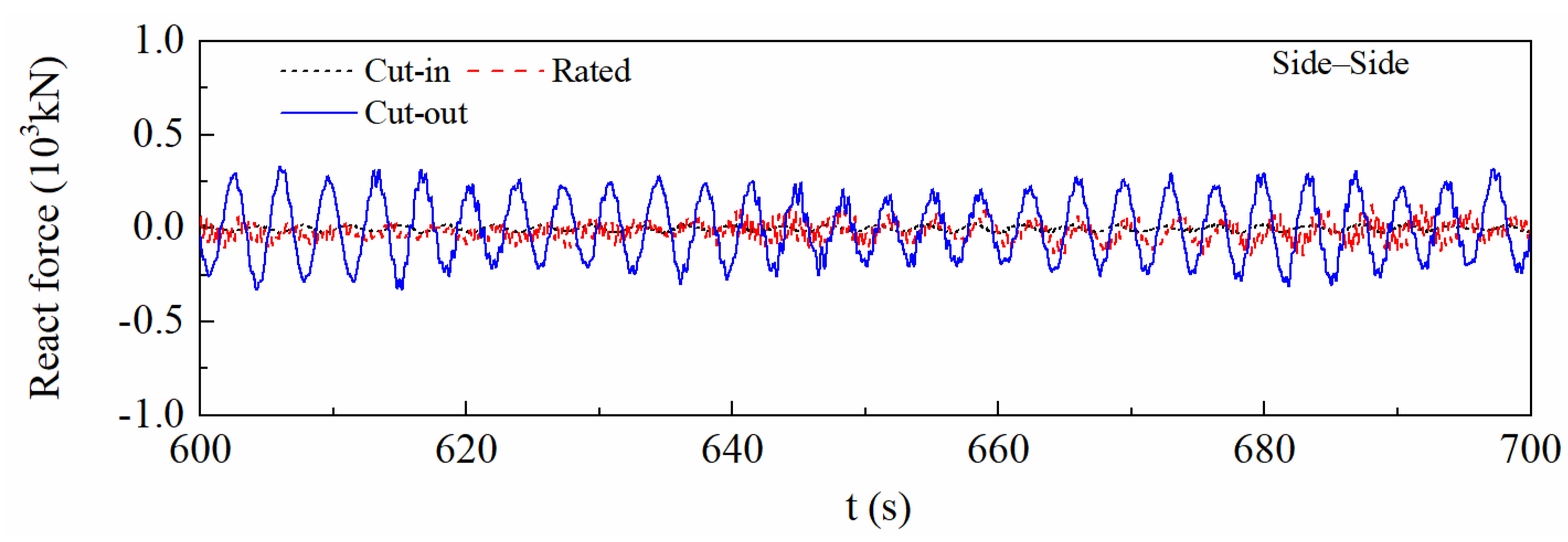
Figure 15 respectively illustrate the reaction force time-history responses of the tower foundation along the F-A and S-S directions, which corroborate the characteristics of aerodynamic loads and tower displacements discussed earlier.
For the F-A direction, the reaction force amplitude under the rated condition is significantly higher than those under other conditions: the time-history exhibits quasi-periodic fluctuations within the range of −1.5 × 10³ kN to 2.0 × 10³ kN. The reaction force amplitudes under the cut-in condition and cut-out condition are notably reduced.
Foundation reaction characteristics are in strong agreement with the upper aerodynamic loads and tower dynamic responses, which quantitatively validates the full-chain dynamic transmission mechanism of the monopile OWT system, spanning aerodynamic loads, tower structural response, and foundation reactions.
In the S-S direction, the reaction force fluctuates symmetrically around zero. The cut-out condition has the largest fluctuation amplitude, followed by the rated condition, and the cut-in condition has the smallest amplitude.
The reaction force time-history characteristics in both directions are fully consistent with the amplitude hierarchies of aerodynamic loads and tower displacements discussed earlier. The quasi-periodic fluctuations of F-A reaction forces confirm the dynamic transmission dominated by the first-order mode, while the large-amplitude fluctuations of S-S reaction forces under the cut-out condition further support the conclusion of higher-order mode participation.
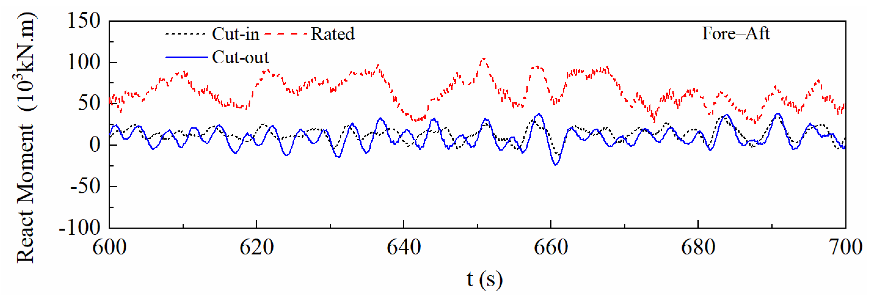
Figure 16 and
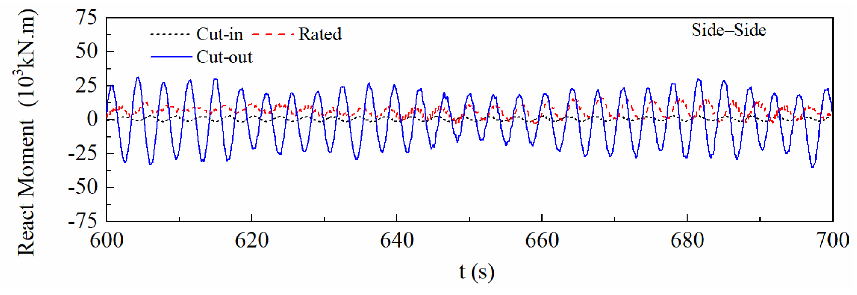
Figure 17 respectively illustrate the reaction moment time-history responses of the tower foundation along the F-A and S-S directions, forming a complete corroboration with the characteristics of upper aerodynamic loads and tower deformation.
For the F-A direction, the reaction moment under the rated condition exhibits the largest amplitude with a significant positive bias, and the time-history presents quasi-periodic fluctuations. The reaction moment under the cut-out condition shows negative fluctuations, while the reaction moment under the cut-in condition is close to zero with mild fluctuations.
In the S-S direction, the reaction moments under all conditions fluctuate symmetrically around zero. Among these, the cut-out condition has the largest fluctuation amplitude, followed by the rated condition, and the cut-in condition has the smallest amplitude.
The time-history characteristics are fully consistent with the amplitude hierarchies of upper aerodynamic loads and tower displacements: the F-A foundation bending moment shows a significant positive bias, which is caused by the steady axial thrust of the rotor under operating conditions, while the S-S foundation bending moment fluctuates symmetrically around zero, because the S-S excitation is dominated by random lateral turbulence without steady directional load. This reveals the intrinsic cause of the different time-history characteristics of foundation reactions in the two directions. The positive bias and quasi-periodic fluctuations in the F-A direction confirm the dominant role of the first-order bending mode, while the large-amplitude symmetric fluctuations of the S-S reaction moment under the cut-out condition further support the conclusion of higher-order mode participation.
4. Influence of the Velocity and Wave on the Dynamic Response of OWT
During service, OWTs encounter severe wind–wave loads exceeding their cut-out speed (vref = 25 m/s). These over-cut-out conditions induce significant dynamic loads, exacerbating structural damage. Investigating responses across wind speeds is critical for long-term safety and reliability.
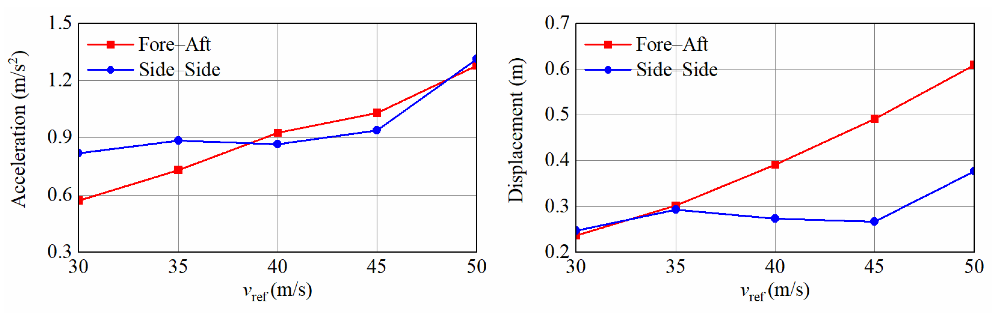
Figure 18 illustrates the influence of
vref on the maximum acceleration and displacement at the tower top in the F-A and S-S directions. The acceleration increases with rising
vref; it is more significant for F-A acceleration. The F-A displacement exhibits a distinct monotonic upward trend with
vref, but the S-S displacement tends to plateau after
vref reaches 35 m/s.
This directional difference is due to the fact that F-A loads are dominated by wind-speed-dependent axial thrust, while S-S loads are governed by lateral turbulence. The S-S displacement plateaus when the reference wind speed exceeds 35 m/s. Quantitative analysis shows that the growth rate of turbulence intensity slows down from 7.2% per 5 m/s wind speed increment (30–35 m/s) to 2.1% per 5 m/s increment (35–50 m/s), while the structural damping increases with the response amplitude, which jointly suppresses the growth of S-S displacement. In contrast, the F-A response is dominated by the steady rotor thrust, which increases monotonically with wind speed, showing a continuous upward trend without plateau.
The influence of
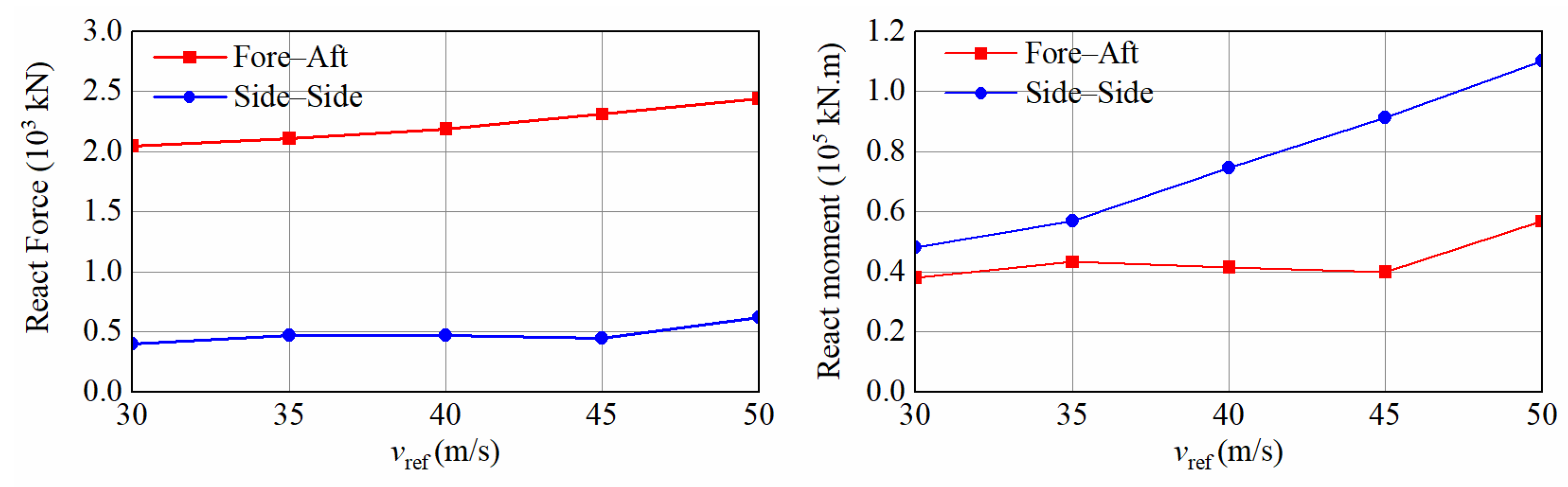
vref on the tower base reaction can be found in
Figure 19. The F-A reaction force maintains relative stability as
vref increases, but the S-S reaction force increases gradually from 0.403 × 10
3 kN to 0.623 × 10
3 kN.
The F-A reaction moment remains nearly constant (0.381 × 10⁵ kN·m) in the vref range from 30 to 45 m/s, followed by a slight upward trend, but the S-S reaction moment increases from 0.482 × 10⁵ kN·m to 1.10 × 10⁵ kN·m. The results are due to the fact that F-A reaction force is mainly induced by the thrust acting on the rotor, whereas the S-S reaction force and moment are caused by the nonlinear increase in lateral turbulence intensity, and the amplitude of the S-S response increases significantly with strengthened turbulence excitation and improved participation of higher-order modes.
5. Discussion
This study investigates the wind–wave coupled dynamic response of the NREL 5MW monopile OWT under cut-in, rated, cut-out and over-cut-out extreme conditions, clarifying the directional discrepancy of structural responses, the intrinsic correlation between aerodynamic damping variation, and the evolution law of structural responses under extreme wind speeds exceeding the cut-out threshold. The findings obtained in this study may provide some preliminary and supplementary reference for the engineering practice of shallow-water monopile offshore wind turbines in similar sea areas. Specifically, the quantitative result that the maximum side–side response occurs under cut-out conditions may serve as a supplementary reminder for the multi-directional load combination design of tower and support structures, while the clarified critical wind speed of 35 m/s for side–side displacement plateau and the nonlinear evolution law of foundation bending moment under over-cut-out wind speeds could offer a basic quantitative basis for the extreme load check and bearing capacity verification of monopile foundations. The verified full-chain dynamic transmission mechanism between aerodynamic loads, tower responses and foundation reactions may also provide a supplementary reference for the simplified dynamic calculation of the turbine system in the preliminary design stage.
This study still has several non-negligible limitations that need to be further addressed in subsequent research. First, all numerical simulations in this study are performed using FAST, without establishing a refined finite element model; therefore, more detailed and high-fidelity numerical research is required to achieve accurate analysis of the stress and strain responses of each structural component of the OWT. Second, nonlinear degradation of soil stiffness under long-term cyclic wind–wave loads and the effect of marine current are not included to focus on the core wind–wave coupling mechanism, which may cause certain deviations between the simulation results and the actual complex marine service environment. Third, this study does not consider the influence of long-term cyclic environmental loads on the fatigue performance of the OWT structure, which is a key issue affecting the long-term service safety of the structure and needs to be systematically investigated in future research.
6. Conclusions
This study systematically investigates the dynamic response evolution characteristics of the NREL 5-MW monopile OWT under wind–wave coupling using fully coupled simulation. A full-operating-condition analysis covering extreme cut-out conditions is performed, the modal participation mechanism is quantitatively clarified, and the influence of wind speed on foundation reactions is parametrically studied. The main conclusions are as follows:
The largest F-A displacement and acceleration can be found in rated conditions due to high-amplitude axial thrust and first-order bending mode dominance, with a peak tower-top displacement of 0.689 m and a maximum acceleration of 1.643 m/s2 at the mid–lower tower. Cut-out conditions exhibit the largest S-S responses driven by higher-order modes activated by reduced aerodynamic damping, with a peak tower-top displacement of 0.429 m and a peak tower-top acceleration of 1.32 m/s2.
Cut-in and rated conditions are dominated by the first-order bending mode, characterized by linear displacement profiles and mid–lower acceleration peaks. Cut-out conditions, however, involve significant higher-order mode participation, leading to nonlinear deformation and top-concentrated S-S acceleration peaks.
F-A displacement and acceleration increase monotonically with vref, driven by wind-speed-dependent axial thrust. S-S displacement plateaus at wind speeds above 35 m/s due to saturated turbulence intensity and enhanced structural damping. Base reactions mirror these trends: F-A bending moment remains stable at 0.381 × 10⁵ kN·m when vref ranges from 30 m/s to 45 m/s, while S-S bending moment grows nonlinearly by 128% as vref increases from 30 m/s to 50 m/s.
The alignment between upper aerodynamic loads, tower responses, and base reactions confirms the dynamic transmission mechanism of the OWT, which verifies first-order mode dominance in the F-A direction and higher-order mode participation in the S-S direction under cut-out conditions.