Article

Oblique Wave Scattering by a Floating Rectangular Porous Box with an Impermeable Bottom


by
Yu-Chan Guo
1,
Sarat Chandra Mohapatra
2,* and
C. Guedes Soares
2,*
1
School of Ocean Engineering, Guangzhou Maritime University, Guangzhou 510725, China
2
Centre for Marine Technology and Ocean Engineering (CENTEC), Instituto Superior Técnico, Universidade de Lisboa, Av. Rovisco Pais, 1049-001 Lisboa, Portugal
*
Authors to whom correspondence should be addressed.
J. Mar. Sci. Eng. 2026, 14(2), 156; https://doi.org/10.3390/jmse14020156
Submission received: 21 December 2025 / Revised: 4 January 2026 / Accepted: 9 January 2026 / Published: 11 January 2026
(This article belongs to the Section Ocean Engineering)

Abstract

Based on linear wave theory and potential flow theory, the wave scattering performance of a rectangular floating porous box with an impermeable bottom is investigated analytically. The mathematical formulation of the physical problem is well established and solved, and its analytical solutions are appropriately obtained using the matched eigenfunction expansion method. The convergency and accuracy of the analytical solutions are carefully verified and thoroughly validated. It is found that the present analytical solutions converge up to three decimal places and agree well with the numerical results published in the previous literature. Furthermore, important numerical results are calculated to thoroughly analyze the oblique wave scattering performance of the proposed rectangular floating porous box with an impermeable bottom and its efficiency in preventing incident waves when used as a floating breakwater. It is concluded that the dimensionless width ( L / h ), submergence depth ( d / h ), and frictional coefficient ( f ) have a significant influence on the scattering performance and the transmission coefficient of the proposed porous box. This work is beneficial for the design and future development of floating rectangular porous box breakwaters.

1. Introduction

Floating breakwaters (FBs) are ocean structures designed to reflect, prevent, and dissipate incident waves, creating peaceful areas for ocean engineering operations. One of their typical forms is the box type, which has been proven efficient in reflecting incident waves through numerous studies investigating the hydrodynamic performance of such FBs [1,2,3,4,5,6,7,8,9]. Due to their simple and convenient design, these FBs have been employed to block waves in oceans and harbors for a considerable length of time. The primary difference among them lies in the various geometries in their cross-sections, with the rectangular cross-section being the most basic and widely studied. The fundamental principle behind their wave prevention function remains the same. Generally, box-type FBs create tranquil water areas primarily by reflecting incident waves. However, it is physically and intuitively impossible to reflect all incident waves just by adjusting the cross-section of box-type FBs. The extremely high wave loads acting on the breakwater surfaces, when subjected to near-total wave reflection, can lead to significant structural damage. Therefore, alternative methods to reduce incident wave amplitude, energy, and forces acting on the FBs must be considered and incorporated.
The porous medium is a rigid body containing pores that are randomly and anisotropically distributed throughout, forming a homogeneous matrix that allows for fluid to pass through [10]. It is assumed that the entire porous medium is saturated with the fluid under investigation. This porous medium attenuates wave energy through interactions between its internal coarse structure and incident waves, thereby decreasing the wave load acting on its surfaces, as the waves can pass through it freely. Additionally, incoming waves of a particular period may lead to extremely large oscillations of the water surface within a harbor, potentially damaging the mooring system of the FBs. By employing a fully nonlinear Boussinesq model FUNWAVE 2.0, Gao et al. [11,12,13] first revealed that Bragg resonant reflection can effectively mitigate harbor resonance based on their investigations on the coupled interactions between various types of incident waves (including regular long waves, bichromatic short wave groups, irregular wave groups), the harbor, and the patch of sinusoidal bars outside the harbor, and also unveiled the inherent mitigating mechanisms via proposing a novel physical process decomposition method. Another effective approach to avoid such potential resonance is to use porous media to radiate or dissipate wave energy, thereby efficiently suppressing oscillations. Furthermore, porous media can be fabricated into any desired shape and easily deployed at any location in the ocean. All of these advantages make the porous medium an excellent choice for use as FBs, and numerous studies have been conducted to investigate the efficiency of such porous breakwaters in blocking incident waves [14,15,16,17].
Research on porous breakwaters primarily focuses on rigid and flexible thin plate/membrane types [18,19,20,21,22] and thick box types [23,24,25]. The fundamental theories for describing fluid motion inside the porous box breakwater and predicting ocean wave reflection and transmission at a permeable breakwater with a rectangular cross-section were introduced and derived in [26,27]. They appropriately obtained the linearized Bernoulli equation for flow in large-scale granular media with quasi-linear damping, along with the homogenous free surface boundary condition applicable to the fluid domain inside the porous medium, to describe the flow and pressure field within the interstices of the granular media. Their work provided a modification to Darcy’s law that has been extensively used by many researchers [28].
Further, Huang [29] studied the inertial effect of a finite thickness porous wavemaker located in an infinite one-dimensional channel. It was found that the hydrodynamic pressure force acting on the porous wavemaker is generally greater than that of an impermeable wavemaker. The thickness of the porous wavemaker significantly affects the hydrodynamic pressure at the water/porous wavemaker interface when the thickness is small, while it has an insignificant effect on the wave profile. Additionally, Dalrymple et al. [30] studied the oblique wave reflection and transmission from porous structures. Yu and Chwang [28] analyzed wave motion through a two-layer porous structure and investigated the reflection, transmission, and dissipation of incident waves by a rectangular porous block with typical dissipative characteristics and various thickness, as well as its crest submergence based on the method of matched velocity potentials. Stiassnie and Drimer [31] derived an analytical solution for the interaction of a linear shallow water wave with a freely floating porous box. The relatively small drift forces obtained indicate advantages for the future use of porous structures as floating breakwaters. Next, Pérez-Romero et al. [32] evaluated the performance of a porous breakwater under the action of a normally incident monochromatic wave train using a simple analytical method based on the potential flow model and a set of experimental tests on a rectangular porous structure. Liu and Li [33] studied the wave reflection and transmission performance of a surface-piercing porous box-type breakwater using a velocity potential decompositions procedure. Liu et al. [34] examined the oblique wave scattering by porous rubble-mound structures based on linear potential theory, where the complex root finding algorithm is avoided by applying a contour integral technique. All these investigations concentrate on surface-piercing rectangular porous structures extended to the seabed, which are costly to construct.
On the other hand, much attention has also been paid to fully submerged porous box-type breakwaters located below the water free surface and with a height lower than the water depth. Rojanakamthorn et al. [35] developed a mathematical model of wave transformation over a submerged permeable breakwater. Neves et al. [36] obtained an analytical solution for waves propagating through a horizontal porous plate of finite thickness based on the Matched Eigenfunction Expansion Method (MEEM) to assess the plate’s performance regarding incident short- and long-wave energy reduction. The behavior of the structure was analyzed for different plate characteristics, and its response to incident short waves was considered. It was found that the transmitted short-wave amplitude increases with relative submergence and decreases with porosity, relative thickness, and width of the plate. Lan and Lee [37] theoretically studied the problem of incident waves propagating over a submerged poro-elastic structure. Moreover, Li et al. [38] developed new analytical solutions to oblique wave scattering by a submerged porous (rubble mound) breakwater based on linear potential theory. They successfully avoided the complex roots of the complex dispersion equations for water wave motion over porous/perforated structures by using a contour integral technique. Later, Guo et al. [23] investigated oblique wave scattering by a composite breakwater consisting of a thin submerged porous-flexible membrane and a rectangular submerged porous structure, employing the MEEM. Jandaghian et al. [39] introduced a weakly compressible Smoothed Particle Hydrodynamics model for accurate simulation of free-surface flows and wave interactions with a submerged rectangular permeable breakwater. Magdalena and Nathanael [40] developed a mathematical model to evaluate the effectiveness of submerged rectangular porous breakwaters in reducing wave amplitudes over a linear transition bottom.
Considering the disadvantages of the high construction costs associated with surface-piercing rectangular porous structures extending to the seabed, as well as the free incident wave transmission across the gap between the water surface and the fully submerged rectangular porous structure, the floating porous breakwater with a finite submergence (less than the water depth) is believed to be a good configuration for floating breakwaters (FBs), although few studies have been conducted on such structures. Park et al. [41] performed a hydrodynamic analysis of floating compound platforms with porous media. They found that a wide porous medium with appropriate porosity and resistance coefficients helps reduce wave exciting forces and the overall wave field levels in the long-period region. Building on the work of Park et al. [41], Park and Kim [42] derived an analytical formulation for obtaining hydrodynamic solutions of an infinitely long floating box-type compound breakwater with wide porous media. They concluded that increasing porosity decreases the reflection and transmission coefficients, and as the relative wavenumber increases, more wave energy dissipation occurs. The hydrodynamic coefficients of an array of vertical porous breakwater under regular waves are studied based on model tests [43] and wave attenuation performance was investigated for different FB structures and vertical plate types in [44]. Moreover, Luo et al. [45] analyzed the performance of single box-shaped porous floating breakwaters, constructed from cubically packed stainless-steel spheres, considering four different mooring systems. However, their studies were conducted by model test instead of analytical methods. On the other hand, studies related to the finite-submerged floating porous breakwater deployed in front of various structures have also been conducted. The effect of wave and current conditions on a floating flexible membrane breakwater via wave quantities was investigated analytically and compared with experimental test results in [46]. Jain and Bora [47] examined the wave interaction with a rigid floating structure, placed after two distinct rigid rectangular porous structures, to mitigate wave-induced forces acting on the floating structure.
To overcome the disadvantages of surface-piercing rectangular porous structures and fully submerged porous breakwaters while retaining their advantages, a new type of floating breakwater is proposed: a floating rectangular porous box with finite submergence depth and an impermeable bottom. This study will investigate the oblique wave scattering characteristics of the breakwater using analytical methods, neglecting the motion of the object in the fluid described by the coupled equations (Kelvin-Kirchhoff equations [48,49]). Furthermore, the incident wave-blocking efficiency will be analyzed by examining the influence of various design parameters on the reflection, transmission, and dissipation coefficients, as well as the dimensionless wave force acting on its impermeable bottom under oblique wave incidence and the dimensionless free-surface elevation in front of, within, and behind the porous breakwater. The analytical methods employed in this research are founded on the MEEM to derive the velocity potentials corresponding to each region. Such analytical investigation methods are characterised by their speed, accuracy, and convenience when compared with the versatility of addressing any shape of boundary offered by numerical methods and the persuasive value in reflecting realistic conditions held by experimental methods. However, both the numerical and experimental methods require significant time and financial resources, which emphasise the advantages of analytical methods in computational costs. Nonetheless, it is important to note that the applicability of analytical methods is limited by the requirement for prior knowledge of solutions [42].
The structure of this study is as follows: Section 2 presents the mathematical formulation of oblique wave interaction with the proposed breakwater; Section 3 introduces the method used to derive the solution, while the convergence and accuracy of the analytical solutions are verified and validated in Section 4. Furthermore, interesting results and corresponding discussions are provided in Section 5, and the important conclusions of this work are summarized in Section 6.

2. Model Formulation

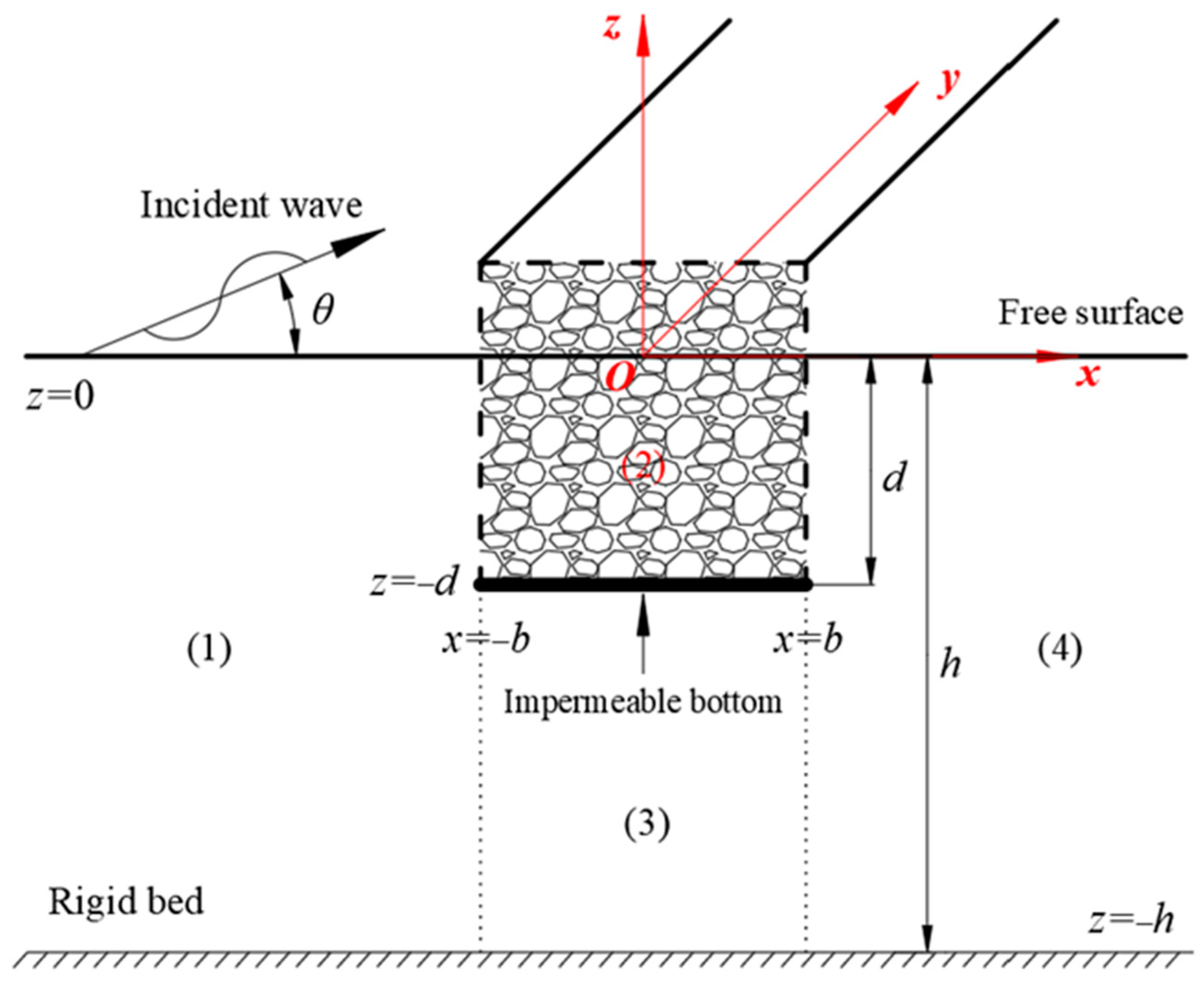
Based on linear wave theory and potential flow theory, the mathematical formulation of the physical problem of oblique wave scattering by a floating rectangular porous box with an impermeable bottom is presented in detail in this section. As shown in Figure 1, a Cartesian coordinate system ( x ,   y ,   z ) with origin O is defined to properly formulate the physical problem. In this system, the x y plane coincides with the water surface, and the z -axis is located along the centerline of the rectangular box, pointing positively upwards. A regular incident wave with wave period ω interacts with the floating rectangular porous box over a flat seabed of constant water depth h , propagating along the positive x-axis at an incidence angle θ . The infinitely long floating rectangular porous box extends along the y-axis with width L = 2 b along the x-axis and a submergence depth d along the z -axis, with the bottom of the box being impermeable. Further, the entire fluid domain is divided into four regions, which are defined as follows: x < b ,   h z 0 ; region 2: − b x b ,   d z 0 ; region 3: b x b ,   h < z < d ; region 4: x > b ,   h z 0 . The velocity potential, Φ j , describing fluid motion and the free surface elevation, η j , in each region can be expressed in the following form:
Φ j x , y , z ; t = Re ϕ j x , z exp i ω t l y ,
η j x , y ; t = Re η j x exp i ω t l y ,
where j = 1 ,   2 ,   3 ,   4 ,   5 , and Re {⋅} denotes the real part of the variable, ω is the angular frequency of the incident wave, t is time, and l = k 0 s i n θ is the y -component of the incident wave number k 0 .
The spatial velocity potential of the incident wave is expressed as follows:
ϕ I x , y = I 0 cosh k 0 ( h + z ) cosh ( k 0 h ) e i α 0 ( x + b ) ,
with α 0 = k 0 c o s θ , i = √−1, I 0 being the incident wave amplitude, g the acceleration due to gravity, and I 0 = i g A / ω e x p ( i α 0 b ) with A is the incident wave amplitude. The incident wave number k 0 satisfies the dispersion relation ω 2 = g k 0 t a n h ( k 0 h ) .
Based on potential flow theory, the velocity potentials of each region satisfy the reduced wave equation, which is derived from the Laplace governing equation and is given by [19,20,23,30]
2 Φ j x 2 l 2 Φ j + 2 Φ j z 2 = 0 ,   j = 1 , 2 , 3 , 4 ,
Outside the floating rectangular porous box, the velocity potentials must satisfy the boundary conditions on the free surface [50], the seabed [30,50], and the Sommerfeld radiation conditions in the far field [19,20,23]:
Φ j z K Φ j = 0 ,   z = 0 ,   j = 1 , 4 ,
Φ j z = 0 ,   z = h ,   j = 1 , 3 , 4 ,
Φ x , y , z ; t = Φ I x , y , z ; t + R 0 Φ i x , y , z ; t as   x T 0 Φ I x , y , z ; t as   x + ,
where K = ω 2 / g . R 0 and T 0 are the reflection and transmission wave amplitudes, respectively. The fluid pressure outside the porous box can be obtained from the Bernoulli equation as
P j = ρ ( i ω Φ j g z ) ,     j = 1 , 3 , 4 .
However, inside the floating rectangular porous box, the free surface condition and the Bernoulli equation change to the following form [26,27,30]:
Φ j z + K ( i f S ) Φ j = 0 ,   z = 0 ,   j = 2 ,
S Φ j t + P j ρ + g z + f ω Φ j = 0 ,   j = 2 ,
where f and S refer to the friction and inertial coefficients of the porous medium, respectively. It may be mentioned that the identical signs before P j / ρ and g z are due to the positive direction of the z -axis. The inertial coefficient S is given by
S = 1 + 1 ε C m / ε ,
with C m being the virtual mass coefficient of medium grains of porous media. It is a known quantity for isolated simple shapes, but generally unknown for random, densely packed materials. The frictional coefficient f is calculated by the following equation:
f = 1 ω h 0 d z b b d x t t + T ε 2 v q 2 K p + C f ε q 3 K p d t h 0 d z b b d x t t + T ε q 2 d t
with v being the kinematic viscosity, K p being the intrinsic permeability of the porous medium, C f being a dimensionless turbulent resistance coefficient inside the porous medium, ε being the porosity of the medium, T being the incident wave period, q being the instantaneous Eulerian velocity vector at a point of the flow field inside the porous medium, and t being the time. The derivation procedure for f and S is detailed, introduced by Chwang and Chan [10], Sollitt and Cross [26,27], and Dalrymple et al. [30]. The porosity ε has a direct influence on both the friction coefficient f and the inertia coefficient S . Additionally, the fluid pressure inside the porous box can therefore be obtained from Equation (9a) as
P j = ρ ω ( i S + f ) Φ j g z , j = 2 .
Further, the velocity potentials must also satisfy the impermeability condition at the bottom of the box:
Φ j z = 0 ,   z = d ,   j = 2 , 3 .
Moreover, since the fluid motion in adjacent regions must be continuous, the fluid pressure and horizontal mass flux should also be continuous at the interface x = ± b between the regions. In equation form, they are given by
Φ j = ( S i f ) Φ 2 , d z 0 Φ 3 , h y d ,   j = 1 , 4 ,
Φ j x = ε Φ 2 x , d z 0 Φ 3 x , h y d ,   j = 1 , 4 ,
with ε being the porosity of the rectangular box.

3. Analytical Solution

Based on the reduced wave Equation (4) and the boundary conditions given in Equations (5)–(8) and (10), the velocity potentials in each wave region are solved using the method of separation of variables and are expressed as follows:
Φ 1 ( x , y , z ; t ) = I 0 cosh k 0 ( h + z ) cosh ( k 0 h ) e i α 0 ( x + b ) + n = 0 R n cosh k n ( h + z ) cosh ( k n h ) e i α n ( x + b ) e i ( ω t l y ) ,
Φ 2 ( x , y , z ; t ) = n = 0 C n cos ( v n x ) cos ( v n b ) + D n sin ( v n x ) sin ( v n b ) cosh p n ( d + z ) cosh ( p n d ) e i ( ω t l y ) ,
Φ 3 ( x , y , z ; t ) = n = 0 A n cosh ( β n x ) cosh ( β n b ) + B n sinh ( β n x ) cosh ( β n b ) cos γ n ( h + z ) e i ( ω t l y ) ,
Φ 4 ( x , y , z ; t ) = n = 0 T n cosh k n ( h + z ) cosh ( k n h ) e i α n ( x + b ) e i ( ω t l y ) ,
with the wave numbers α n and k n in regions 1 and 4 are obtained from the following equation:
α n = k n 2 l 2 ,   n = 0 , 1 , 2 , ,
along with the following dispersion relation
K = k n tanh ( k n h ) ,   n = 0 , 1 , 2 , .
Meanwhile, the complex wave numbers γ n and p n in region 2 are determined by solving the equation
v n = p n 2 l 2 ,   n = 0 , 1 , 2 , ,
as well as the complex dispersion relation that includes the friction and inertial coefficients, given as follows:
K ( S i f ) = p n tanh ( p n d ) ,   n = 0 , 1 , 2 , ,
The wave numbers β n and γ n in region 3 are obtained from the following two equations, respectively:
β n = γ n 2 + l 2 ,   n = 0 , 1 , 2 , ,
γ n = n π h d ,   n = 0 , 1 , 2 , .   where   h d
Furthermore, the vertical eigenfunctions in regions 1–4 satisfy the following orthogonal relations:
X m n = d 0 cosh p m ( d + z ) cosh p n ( d + z ) d z = [ 2 p n d + sinh ( 2 p n d ) ] / 4 p n , m = n 0 , m n ,
Y m n = h d cos γ m ( h + z ) cos γ n ( h + z ) d z = h d , m = n = 0 0.5 ( h d ) , m = n 0 0 , m n ,
Z m n = h 0 cosh k m ( h + z ) cosh k n ( h + z ) d z = 2 k n h + sinh ( 2 k n h ) / 4 k n , m = n 0 , m n ,
Taking and applying Equations (13)–(16) to the pressure continuity condition (11), we multiply the vertical eigenfunctions c o s h p m ( d + z ) of region 2 and c o s γ m ( h + z ) of region 3 to both sides of the above equation. Then, by integrating with respect to z in their corresponding regions, z [ d ,   0 ] and z [ h ,   d ] , four equations are obtained, as follows:
n = 0 ( S i f ) X m n cosh ( p n d ) C n n = 0 ( S i f ) X m n cosh ( p n d ) D n n = 0 U m n cosh ( k n h ) R n = I 0 U m 0 cosh ( k 0 h ) ,   m = 0 , 1 , 2 , 3 , , N ,
n = 0 Y m n A n n = 0 Y m n tanh ( β n b ) B n n = 0 D m n cosh ( k n h ) R n = I 0 D m 0 cosh ( k 0 h ) ,   m = 0 , 1 , 2 , 3 , , N ,
n = 0 ( S i f ) X m n cosh ( p n d ) C n + n = 0 ( S i f ) X m n cosh ( p n d ) D n n = 0 U m n cosh ( k n h ) T n = 0 ,   m = 0 , 1 , 2 , 3 , , N ,
n = 0 Y m n A n + n = 0 Y m n tanh ( β n b ) B n n = 0 D m n cosh ( k n h ) T n = 0 ,   m = 0 , 1 , 2 , 3 , , N ,
with
U m n = d 0 cosh p m ( d + z ) cosh k n ( h + z ) d z ,   D m n = h d cos γ m ( h + z ) cosh k n ( h + z ) d z
Similarly, by applying Equations (13)–(16) to the fluid motion velocity continuity condition (12) and multiplying the vertical eigenfunction c o s h k m ( h + z ) of regions 1 and 4 to both sides of the equation, and integrating with respect to z over the region z [ h ,   0 ] , two equations are obtained, as follows:
n = 0 β n tanh ( β n b ) D n m A n + n = 0 β n D n m B n + n = 0 ε v n U n m tan ( v n b ) cosh ( p n d ) C n + n = 0 ε v n U n m cot ( v n b ) cosh ( p n d ) D n n = 0 i α n Z m n cosh ( k n h ) R n = i α 0 I 0 Z m 0 cosh ( k 0 h ) ,   m = 0 , 1 , 2 , 3 , , N ,
n = 0 β n tanh ( β n b ) D n m A n + n = 0 β n D n m B n n = 0 ε v n U n m tan ( v n b ) cosh ( p n d ) C n + n = 0 ε v n U n m cot ( v n b ) cosh ( p n d ) D n + n = 0 i α n Z m n cosh ( k n h ) T n = 0 ,   m = 0 , 1 , 2 , 3 , , N .
The Newton method and the perturbation method [19,51] are used to solve the complex dispersion relations (18) and (20), respectively. Once the wave numbers in regions 1, 3, and 4, as well as the complex wavenumbers pn in region 2, are determined, the remaining unknowns in the mathematical expressions for the velocity potentials (13)–(16), namely A n ,   B n ,   A n , D n ,   R n and T n , can be solved using the system of equations given by Equations (26)–(31). To ensure the system is square, the infinite series in these equations are truncated after N + 1 terms for all unknowns, forming a square system of size 6(N + 1) × 6(N + 1).
Based on the solved expressions for the velocity potentials in each region, various hydrodynamic characteristics related to the floating box and the propagating waves, such as the transmission coefficient K t , the reflection coefficient K r , the dissipation coefficient K d , the dimensionless wave forces K f acting on the impermeable bottom of the floating rectangular porous box, as well as the free surface elevation amplitudes in front of, within and behind the proposed breakwater, can be expressed and calculated using the following formulas.
The transmission coefficient ( K r ), reflection coefficient ( K t ), and dissipation coefficient ( K d ) of the floating rectangular porous box are given by
K t = T 0 I 0 ,
K r = R 0 I 0 ,
K d = 1 K r 2 K t 2 .
The dimensionless wave forces K f acting on the impermeable bottom of the floating rectangular porous box are obtained as
F v = ρ i ω b b ( S i f ) Φ 2 Φ 3 d x ,   a t   z = d ,
K f = F v 10 ρ g h 2 .
The water free surface elevation amplitude in front of ( η 1 ), within ( η 2 ), and behind ( η 4 ) the floating rectangular porous box are given by
η j = i ω Φ j z ,   j = 1 , 2 , 4 ,   a t   z = 0 .

4. Convergence Study and Accuracy Validation

Before calculating any numerical results to investigate the hydrodynamic characteristics of the proposed breakwater, the convergence and accuracy of the present analytical solution need to be verified and validated. Firstly, the convergence of the reflection, transmission, and dissipation coefficients K r , K t , K d as a function of the truncation number N for different values of the dimensionless wave number k 0 h , the dimensionless submergence depth d / h , and the incidence wave angle θ are calculated and summarized in Table 1, Table 2 and Table 3, respectively. It is evident that K r , K t , and K d converge to three decimal places when the truncation number N 60 for all values of the dimensionless variables, which confirms the convergence of the present analytical solution.
Therefore, the series truncation number, gravitational acceleration, and seawater density are set to N = 60 , g = 9.81 m/s2, ρ = 1025 kg/m3 for the numerical calculations in the following sections, unless otherwise stated.
Moreover, it should be noted that all computations in the present study were performed using a 64-bit (Win64) desktop computer. Specifically, the analytical solutions for the effects of different design parameters on the proposed floating breakwater were solved via MATLAB R2024b software. The numerical computations were conducted on a desktop equipped with an Intel® Core i9-14900K processor (3.2–6.0 GHz) and 32 GB of DDR5-4800 RAM, with data stored on a solid-state drive (SSD). On average, each computational case required approximately 5–10 min to complete.
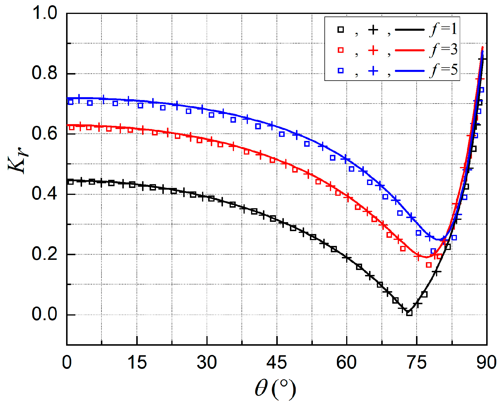
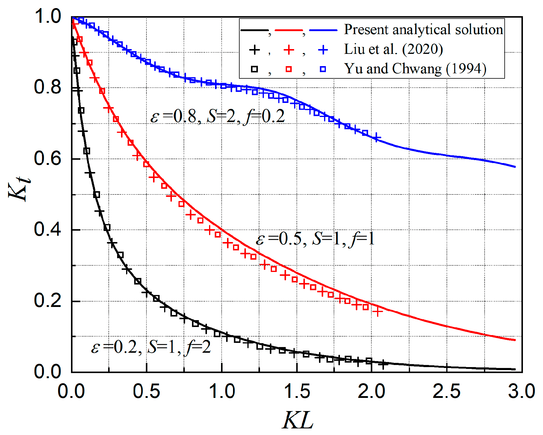
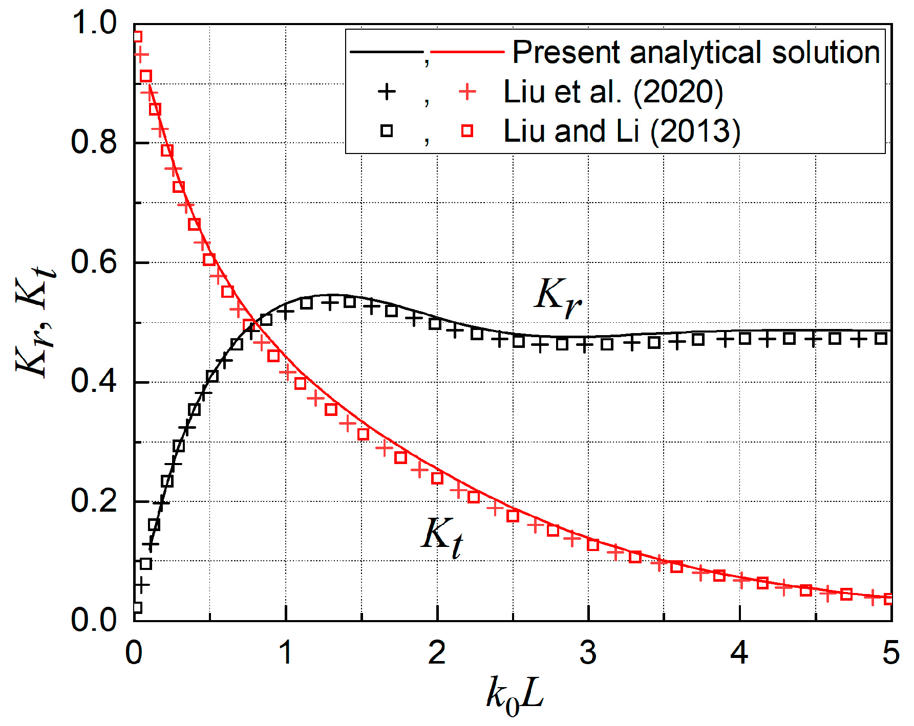
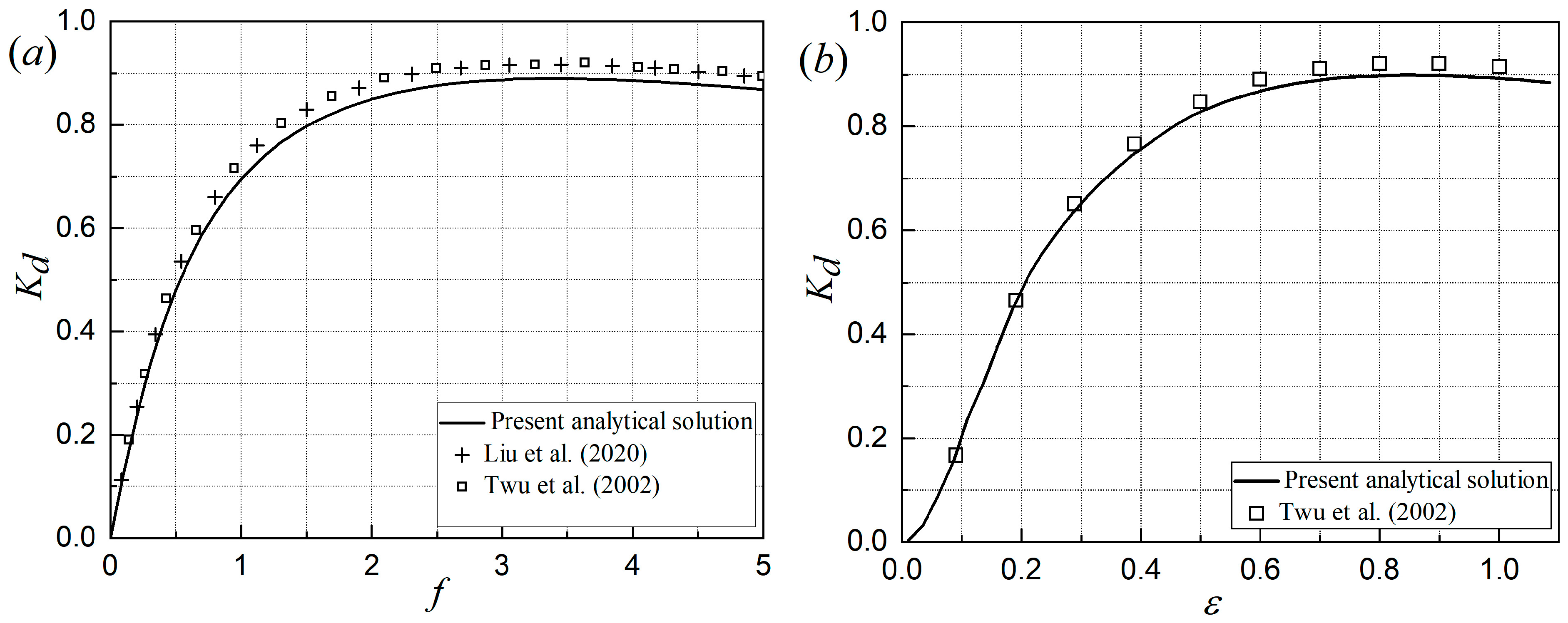
Additionally, as illustrated in Figure 2, Figure 3, Figure 4 and Figure 5, the present analytical solutions are compared with numerical results from previously published papers [28,30,33,34,52]. These comparisons demonstrate that the present analytical solutions are in good agreement with those in the literature, thereby further confirming the accuracy and correctness of the solutions. As shown in Figure 5, the slight divergence between the current analytical solutions and the published results under conditions of larger friction coefficient f values stems from differences in the numerical methods employed to solve the complex dispersion relation (20). Specifically, Liu et al. [34] employed a contour integral technique, whereas the solution method utilized by Twu et al. [52] is not explicitly specified. Although all the aforementioned numerical approaches yield accurate and well-converged results, minor discrepancies among different numerical methods are common in such analyses and generally deemed acceptable in the field.

5. Results and Discussion

As demonstrated in the previous section, the hydrodynamic solutions for a floating rectangular porous box with an impermeable bottom can be calculated using the present analytical method. Using the developed computer codes, wave prevention performance studies were conducted for various dimensionless parameters, including structural length L / h , submergence depth d / h , structural porosity ε, incidence wave angle θ , inertial coefficient f , and frictional coefficient S , in this section.
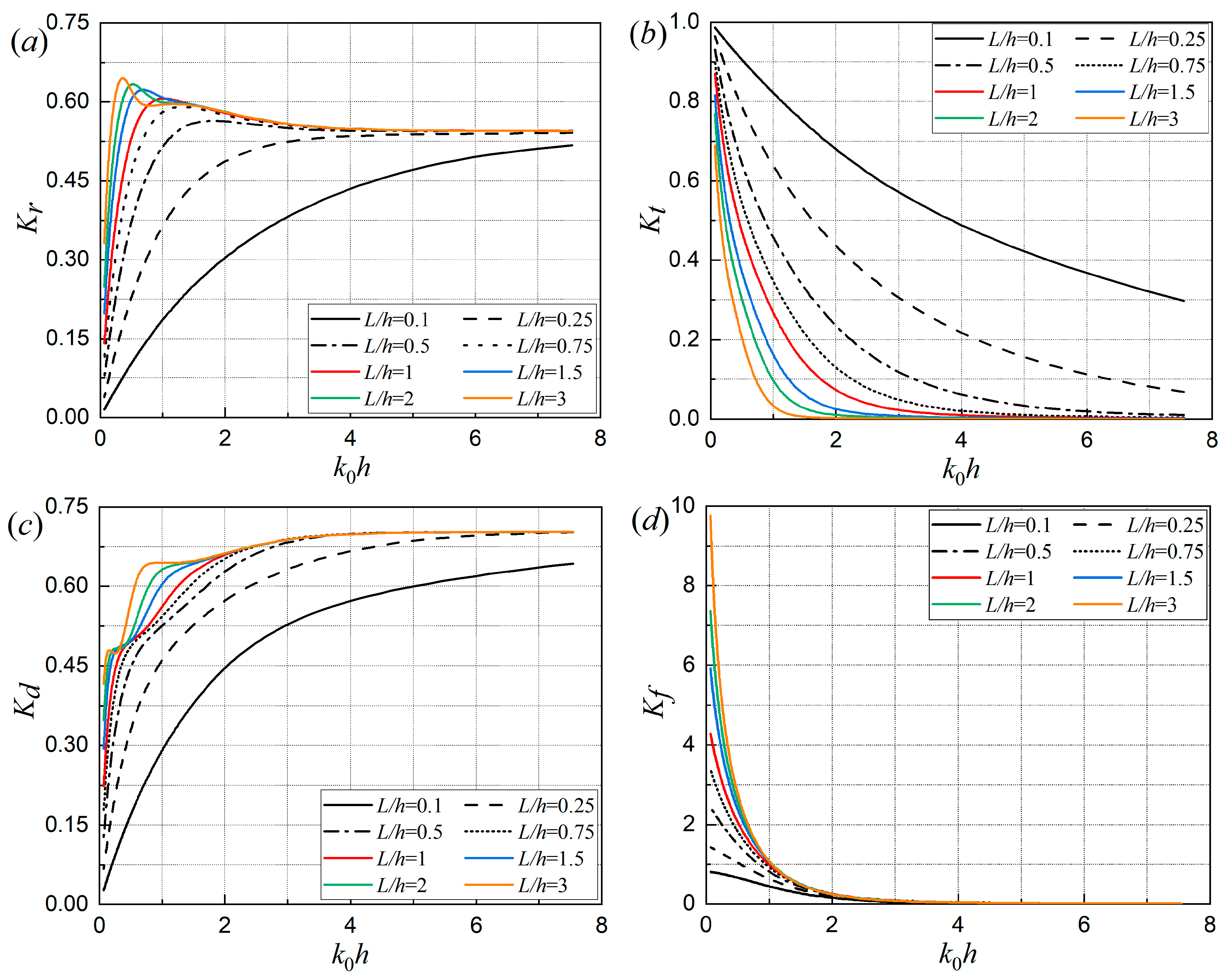
Figure 6 shows the effect of the dimensionless structural length L / h on (a) the reflection coefficient K r , (b) the transmission coefficient K t , (c) the dissipation coefficient K d , and (d) the dimensionless wave force coefficient K f as a function of the dimensionless wave number k 0 h . From Figure 6a, it can be seen that as k0h increases, the reflection coefficient Kr initially rises sharply (with a slope of 0.09–1.3) when k 0 h < 1, then decreases at a small slope approximately 0.02 for most values of L / h (except L / h = 0.1 and 0.25) in the range 1 <   k 0 h < 4, and eventually stabilizes at a constant level when k 0 h > 4.
The stabilization of the reflection coefficient K r at a constant value for k 0 h > 4 stems from the fact that larger dimensionless wave numbers (i.e., k 0 h > 4 ) correspond to incident waves with shorter wavelengths. Although shorter waves intensify the interaction between incident waves and the floating structure, thereby enhancing wave reflection, such enhancement is not unbounded. When the wavelength decreases to a small finite value, the floating breakwater behaves as an infinite structure relative to the incident waves; at this point, further reducing the wavelength (i.e., for shorter incident waves) no longer contributes to additional wave reflection. Meanwhile, the residual wave energy penetrating the porous medium is largely dissipated, resulting in negligible wave transmission for waves whose wavelengths are close to this small finite value or larger than it. This small finite value corresponds to the critical breakwater length, beyond which the wave period exerts an insignificant influence on the reflection coefficient. This phenomenon indicates that the floating rectangular porous box of finite width is most efficient in reflecting incident waves with a particular dimensionless wave number k 0 h . Furthermore, Figure 6b–d illustrates that an increase in k0h leads to a general upward trend in the dissipation coefficient Kd, while the transmission coefficient Kt decreases sharply, following an exponential decay, for L / h 0.75 . Similarly, the dimensionless wave force K f decreases in a similar manner. These constant reflection coefficients and the exponentially decaying transmission coefficients for increasing k0h coincide with the experimental findings of Pérez-Romero et al. [32] for a rectangular porous structure under the action of a normal incident wave.
Moreover, it is evident that a wider floating rectangular box results in greater incident wave reflection, reduced wave transmission, increased wave energy dissipation, and higher wave forces acting on its impermeable bottom. This suggests better performance in creating a tranquility zone behind the porous box for various types of marine operations. In the short-wave region k 0 h   3 , the effect of L / h on the reflection, transmission, dissipation coefficients K r , K t , K d and the dimensionless wave force K f becomes less pronounced and ultimately negligible as k 0 h increases. Therefore, the incident wave prevention efficiency of the box is not sensitive to its width for k 0 h 3 and L / h 0.75 .
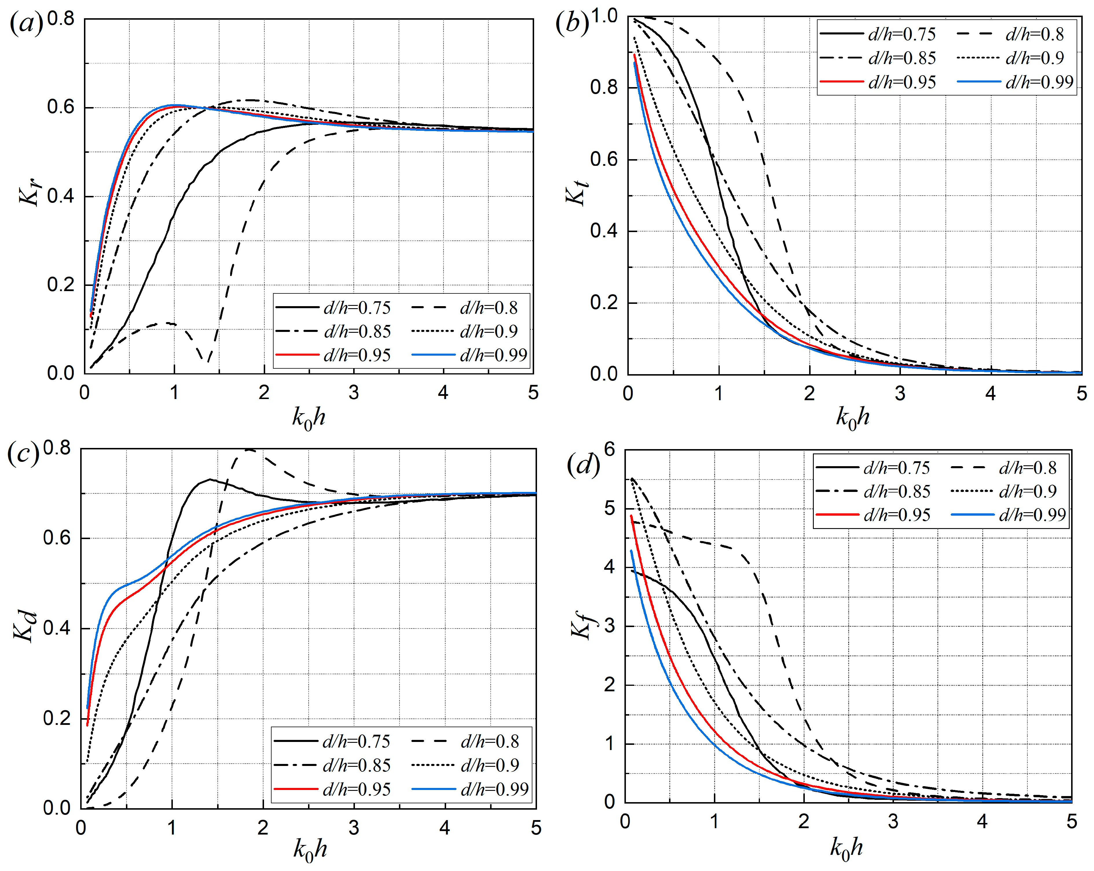
Figure 7 reveals the effect of the dimensionless submergence depth d / h on (a) the reflection coefficient K r , (b) the transmission coefficient K t , (c) the dissipation coefficient K d , and (d) the dimensionless wave force coefficient K f against the non-dimensional wave number k 0 h . It is clear that as the dimensionless submergence depth increases, the reflection and dissipation coefficients K r , K d initially decreases and then rise rapidly, while the transmission coefficient K t and the dimensionless wave force K f exhibit the opposite trend. The worst performance of the rectangular floating porous box in terms of wave reflection, prevention, and dissipation occurs at a non-dimensional submergence depth d / h = 0.8 , which should be avoided when designing such proposed breakwaters.
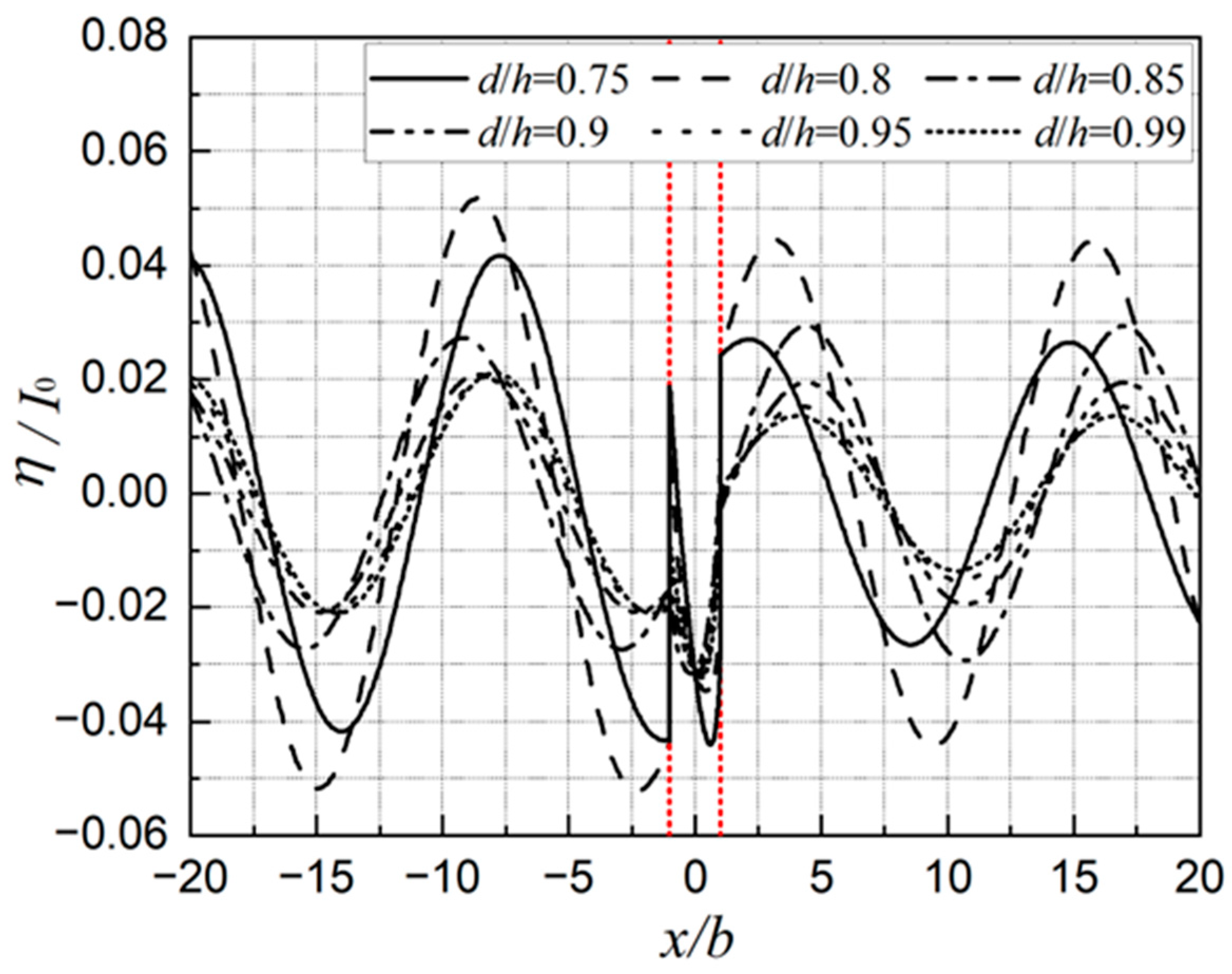
To elucidate the underlying mechanisms responsible for the poorest performance observed at d / h = 0.8 , the non-dimensional free surface elevation η / I 0 in each region for k 0 h = 1 was further calculated and plotted in Figure 8. It can be seen from the elevation curves that no resonance phenomenon is observed either in front of, within, or behind the porous medium. However, a distinct phase lag can be identified in Figure 8. This may be attributed to wave system interference induced by the propagation, reflection, and transmission of incident waves, which consequently results in the proposed floating breakwater exhibiting the lowest efficiency in shielding against and reflecting incident waves at d / h = 0.8 .
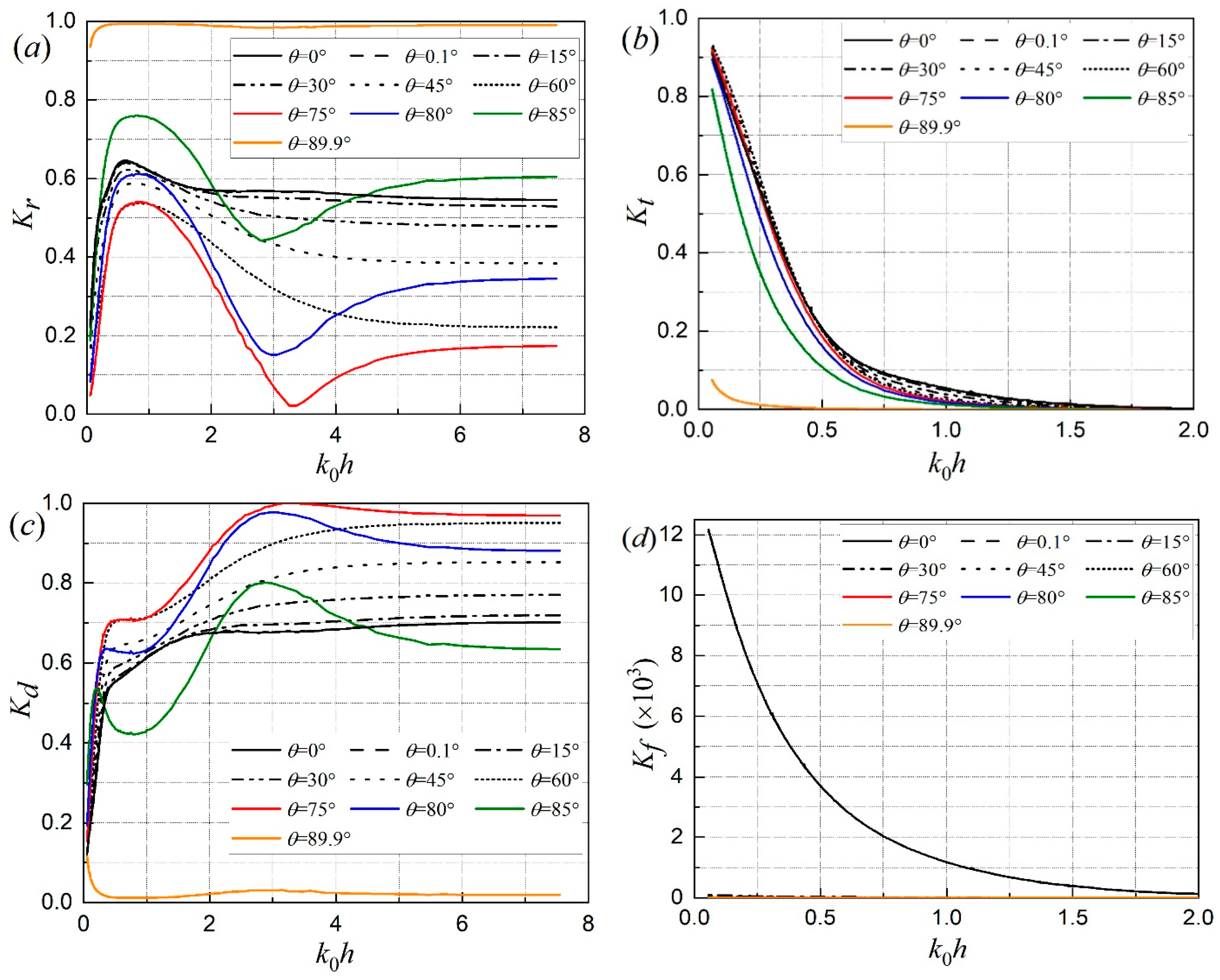
Figure 9 plots the effect of the incidence wave angle θ on (a) the reflection coefficient K r , (b) the transmission coefficient K t , (c) the dissipation coefficient K d , and (d) the dimensionless wave force coefficient K f as a function of the non-dimensional wave number k 0 h . It can be observed from Figure 9a,c that when the incidence wave angle θ 75 °, the reflection and dissipation coefficients K r , K d fluctuate with the dimensionless wave number in the long-wave region ( k 0 h   < 6 ), whereas only one peak appears in the reflection coefficient curves for θ 60 °.
Additionally, as the incidence wave angle θ increases from 0° to 75°, the reflection coefficient K r clearly decreases, with the maximum difference in K r reaching 0.6 at k 0 h = 3.25. Meanwhile, the transmission coefficient Kt increases, with the maximal difference in K t reaching 0.42 at k 0 h = 3~3.5. However, Figure 9b,d shows that the effects of the incident wave angle θ on the transmission coefficient K t and the dimensionless wave force K f are minimal when 0.1 ° θ 75 ° . Instead, beam waves ( θ = 0 ° ) result in much greater wave forces acting on the impermeable bottom of the porous breakwater, indicating that even a slight change in the wave propagation direction (e.g., from θ = 0 ° to θ = 0.1 ° ) can considerably reduce the wave force. This reduction is therefore beneficial to structural safety, although it provides only limited improvement in incident wave-blocking efficiency.
On the other hand, as the incidence wave angle θ increases from 75 ° to 89.9 °, the reflection coefficient K r rapidly increases to nearly 1, while the dissipation coefficient Kd and the transmission coefficient Kt both decrease sharply to nearly 0. This occurs because an incident wave angle of θ = 89.9 ° represents waves propagating perpendicular to the width direction ( x -axis) and parallel to the infinite length direction ( y -axis) of the proposed floating rectangular porous box. As a result, the incident waves approach the box, but the transmitted waves passing through it are negligible. Furthermore, in the long-wave region ( k 0 h < 0.75), the wave force exerted by a beam wave ( θ = 0.1 °) on the impermeable bottom surface of the floating rectangular porous box is at least twice that induced by waves with other incident angles.
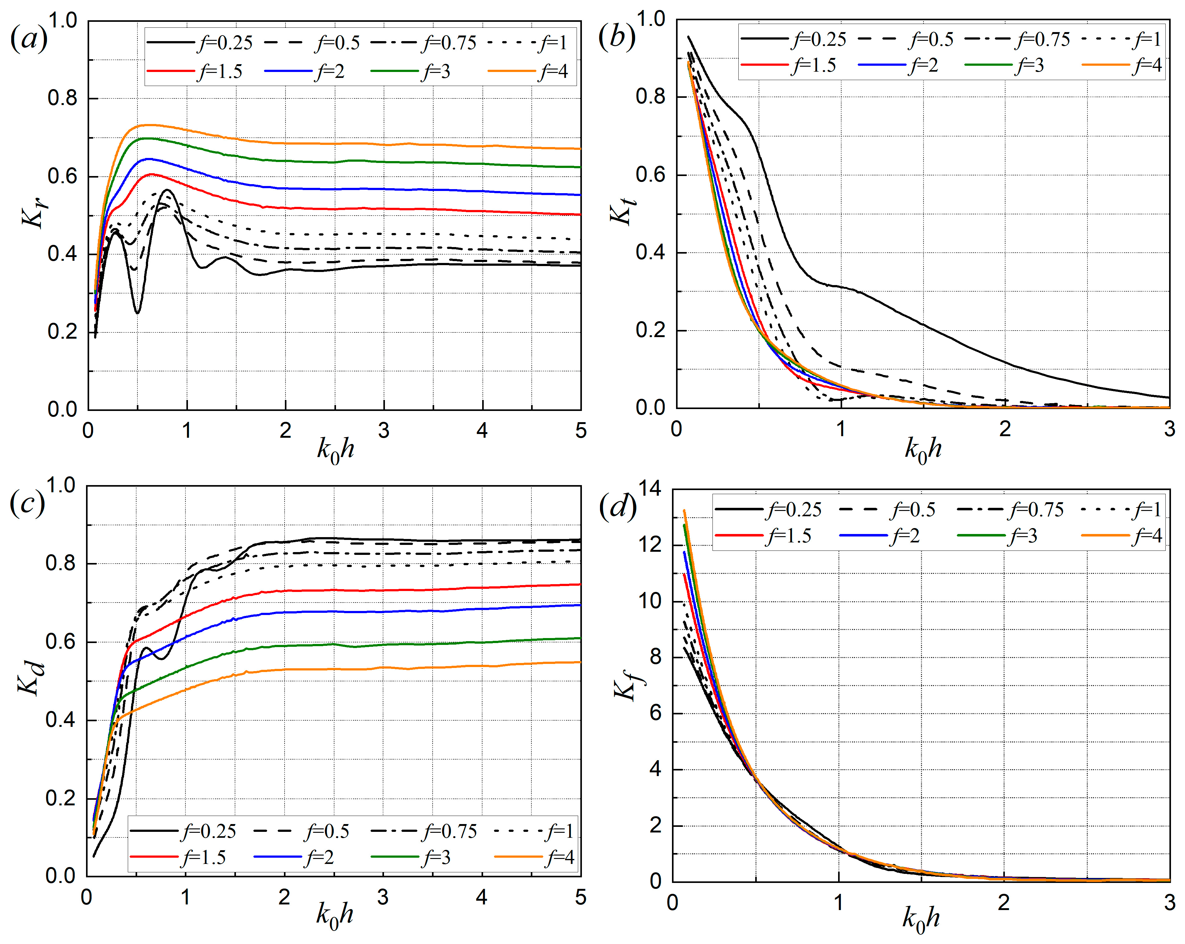
Figure 10 depicts the effect of the frictional coefficient f of the porous box on (a) the reflection coefficient K r , (b) the transmission coefficient K t , (c) the dissipation coefficient K d , and (d) the dimensionless wave force coefficient K f versus the non-dimensional wave number k 0 h . It can be found from Figure 10 that an increase in the frictional coefficient f leads to more incident wave reflection, less wave transmission and energy dissipation, and a larger wave force acting on the box’s impermeable bottom. This occurs because the porosity of the porous medium disrupts the motion of fluid particles, and its frictional characteristics further reduce the fluid’s velocity and amplitude. As a result, fewer incident waves pass through the porous box, leading to lower wave dissipation.
In the long-wave region ( k 0 h   ≤ 2), smaller values of the frictional coefficient f cause the K r and K d curves to exhibit noticeable fluctuations with respect to the dimensionless wave number k 0 h . The smaller the f -value, the more pronounced these fluctuations are. This can be explained by the fact that long waves, with their longer wavelengths, are more likely to maintain their sinusoidal shape as they propagate through the porous medium. Only porous media with higher frictional coefficients create greater roughness between wave-structure interactions, dissipating more wave energy and thus reducing the fluctuations in the K r and K d curves for larger values of f .
In the short-wave region ( k 0 h   > 2), the non-dimensional wave number k 0 h has a negligible effect on K r , K t , K d , and K f , and their corresponding curves for different values of f approximate horizontal straight lines. This indicates that the effects of varying f on K r and K d are stable, while the differences in K t and K f are small and negligible. Moreover, the dimensionless wave force K f is sensitive to the frictional coefficient f only in the long-wave region ( k 0 h   < 0.5), with the effect of f on Kf becoming negligible in the short-wave region ( k 0 h > 0.5 ).
The phenomenon of decreasing frictional coefficients leading to lower reflected wave amplitudes and increasing f reducing wave exciting forces, particularly for long-period waves, was also observed by Park et al. [41] in their hydrodynamic analysis of floating platforms with porous media. They pointed out that this effect is linked to the permeability of the medium.
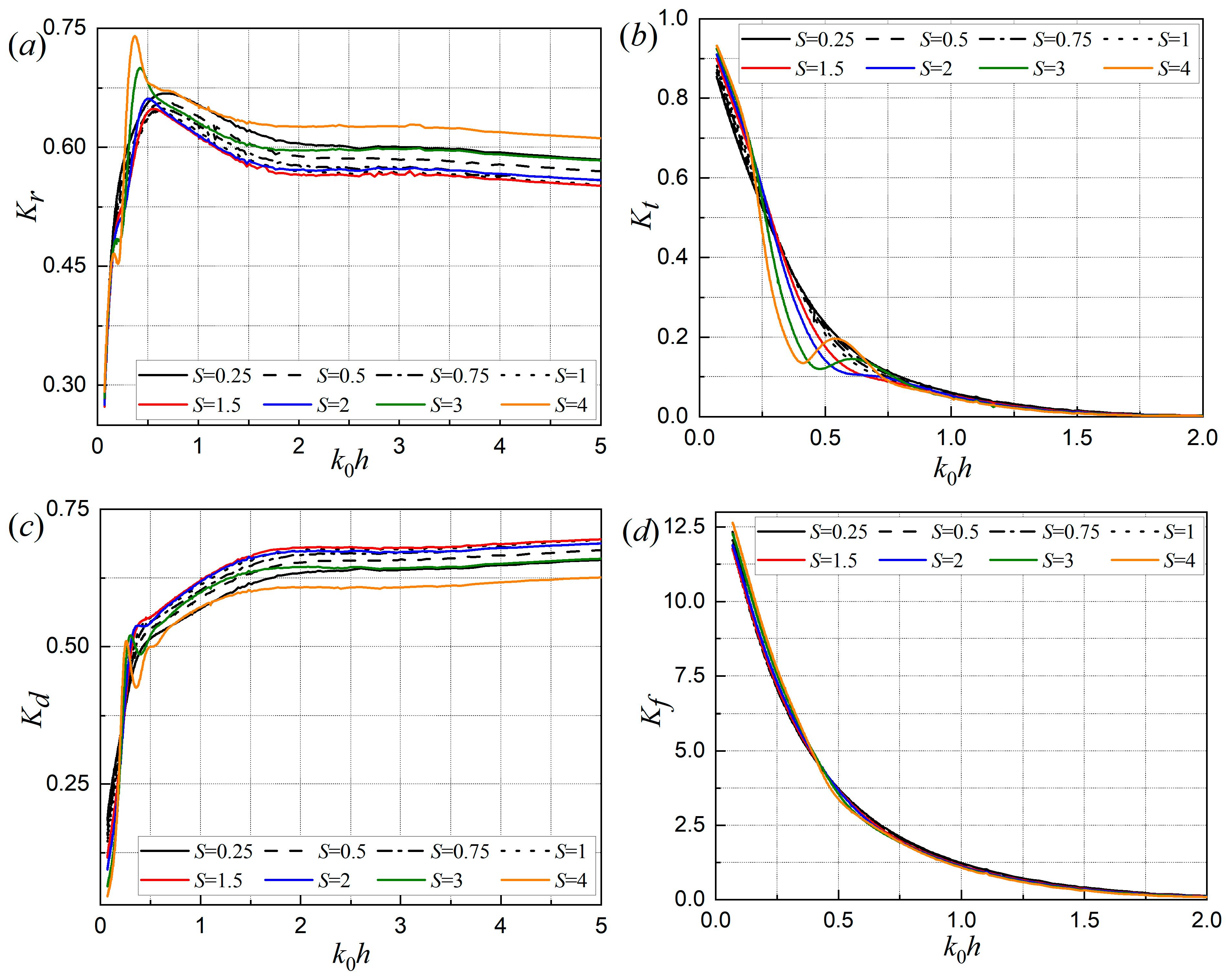
The effect of the inertial coefficient S of the porous box on the (a) K r , (b) K t , (c) K d , and (d) K f versus the non-dimensional wave number k 0 h is shown in Figure 11. Unlike the effect of the frictional coefficient f , as the inertial coefficient S increases, the reflection coefficient Kr initially increases and then decreases, with the minimum reflection and maximum wave energy dissipation occurring at S = 1.5 . However, compared to K r and K d , variations in S primarily affect the transmission coefficient Kt in the wave region 0.25 < k 0 h < 0.75. Specifically, a larger S results in a slightly higher transmission coefficient for k 0 h < 0.25, a lower transmission coefficient for 0.25 < k 0 h < 0.75 , and almost no change in K t for k 0 h > 0.75. Furthermore, Figure 11d shows that the non-dimensional wave force acting on the impermeable bottom of the rectangular floating porous box is largely insensitive to the inertial coefficient S .
Finally, a comparison of Figure 10 and Figure 11 suggests that the frictional coefficient f   has a greater influence on the performance and wave force acting on the box’s bottom than the inertial coefficient S of the porous media. This is because the inertial characteristics of the porous media are related to its mass but do not contribute significantly to wave energy dissipation.
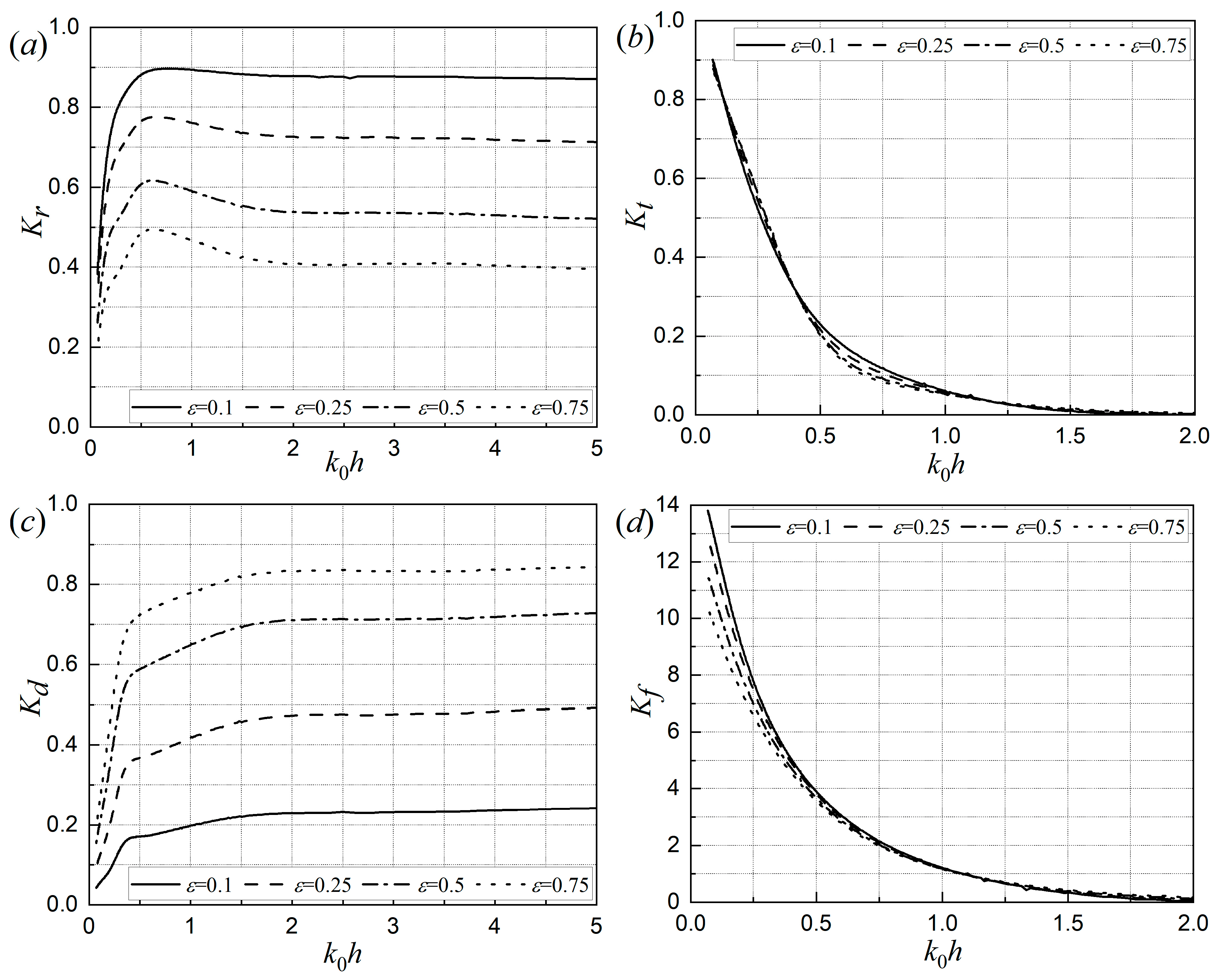
Figure 12 shows the effect of the porosity ε of the porous box on the (a) K r , (b) K t , (c) K d , and (d) Kf as a function of the non-dimensional wave number k 0 h . It is clear form Figure 12a–d that the porosity ε of the porous medium has a significant effect on the reflection and dissipation coefficients K r and K d , but a smaller effect on the transmission coefficient K t and the dimensionless wave force K f . A larger value of porosity ε causes the porous box to reflect fewer incident waves but dissipates more wave energy. As the porosity ε increases from 0.1 to 0.75, wave reflection reduces by 50%, while the dissipated wave energy increases by approximately 60%. This is intuitively reasonable because greater structural porosity allows incident waves can propagate through the porous medium more easily, resulting in more intense wave-structure interactions that dissipate wave energy. In contrast, smaller porosity causes the porous box to behave more like a non-porous box, making it harder for fluid to enter the internal space, and thus less wave energy is attenuated by wave-structure interactions inside the floating box. This phenomenon regarding the variation in the dissipation coefficient K d is consistent with [52], who found that wave energy loss increases monotonically with porosity in their study of wave damping characteristics for vertically stratified porous breakwaters under oblique wave action.
On the other hand, comparing Figure 12b with Figure 10b and Figure 11b, it is evident that the influence of the structural porosity ε on the transmission coefficient K t is smaller than the effects of the frictional and inertial coefficients f and S . Additionally, from Figure 10d and Figure 12d, it can be concluded that the effect of the frictional coefficient f on the dimensionless wave force K f is opposite to that of the porosity ε , with larger porosity leading to a smaller wave force.
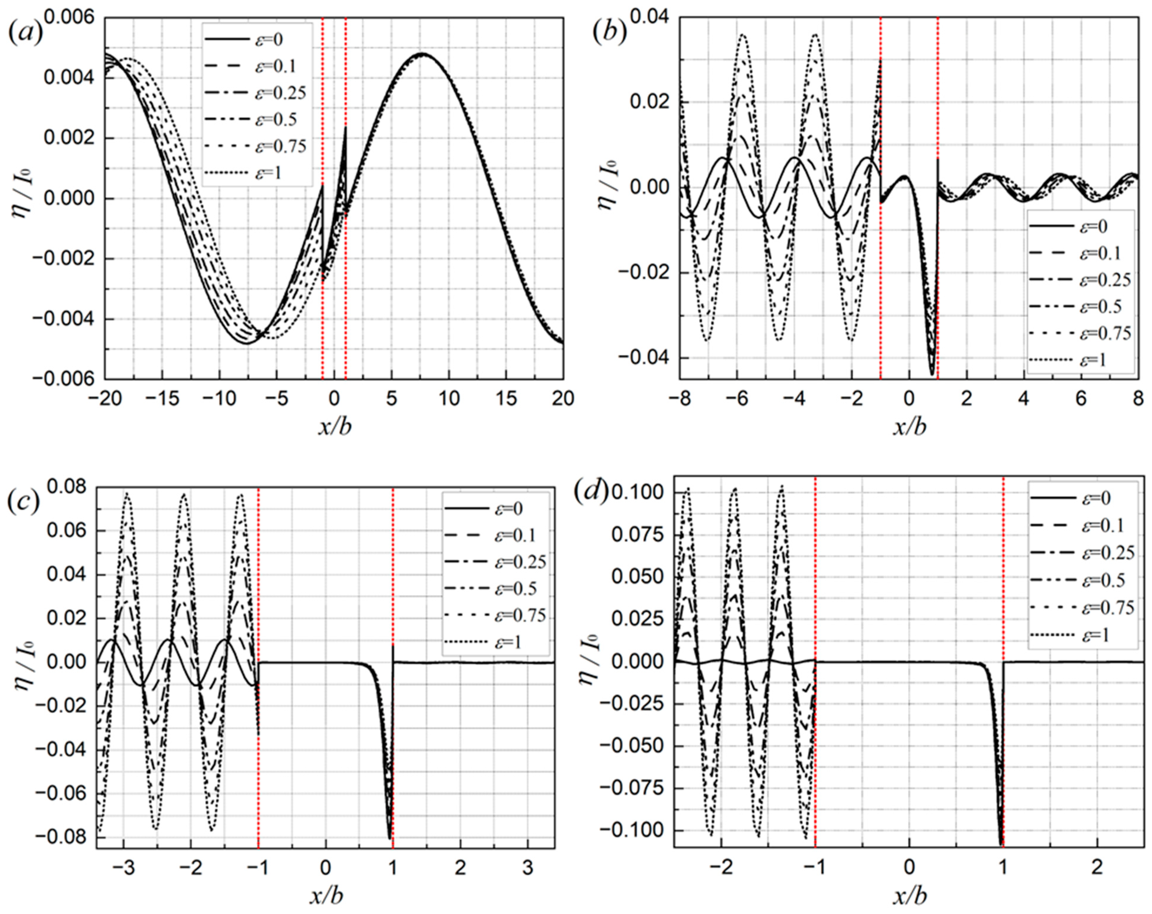
The effects of structural porosity ε on the non-dimensional water free surface elevation amplitude η / I 0 in regions 1, 2, and 4 are shown in Figure 13 for different k 0 h . As seen in Figure 13a–d, the curves for x / b   <   1 , 1     x / b     1 , and x / b   >   1 represent the non-dimensional free surface elevation amplitudes in front of, within, and behind the porous box, respectively.
Figure 13b–d show that the non-dimensional wave amplitudes η / I 0 behind the rectangular floating box are significantly lower than those in front of it. This indicates that the porous box effectively attenuates incident waves with large dimensionless wave numbers ( k 0 h = 1, 3, and 5), regardless of its porosity ε . Furthermore, larger porosity ε leads to higher wave amplitudes in front of the floating porous box, which contrasts with the observations in Figure 13a. This phenomenon may be attributed to the phase superposition of incident and reflected waves, causing larger wave amplitudes as the porosity increases.
Additionally, the effect of structural porosity on the dimensionless free surface elevation amplitude inside and behind the porous box is minimal when the periods of the incident waves are either short ( k 0 h = 3 ,   5 ) or long ( k 0 h = 0.1 ). It can also be concluded that increasing the non-dimensional wave number k0h reduces both the dimensionless free surface elevation amplitude η / I 0 in front of and behind the porous box smaller.
On the other hand, as the dimensionless wave number k 0 h increases from 0.1 to 5, full porosity ( ε = 1 ) leads to a higher free-surface elevation amplitude in front of the floating breakwater. Moreover, structural porosity induces a noticeable phase lag in the free-surface elevation in front of the breakwater, which is observed for all values of k 0 h except k 0 h = 5 . In contrast, zero porosity ( ε = 0 ) yields the lowest free-surface elevation amplitude in front of the breakwater, except in the long-wave case ( k 0 h = 0.1 ). It is also evident that structural porosity exerts a more significant influence on the free-surface elevation amplitude in front of the floating breakwater than on that behind it.

6. Conclusions

Using the matched eigenfunction expansion method, the oblique wave interactions with a floating rectangular porous box with an impermeable bottom have been investigated analytically. The effects of various design parameters, such as the dimensionless width L / h , dimensionless submergence depth d / h , incidence wave angle θ , the frictional and inertial coefficients S and f , and the porosity ε , on oblique waves scattering and blocking performance of the proposed breakwater (a floating rectangular porous box with an impermeable bottom) have been thoroughly calculated and analyzed using the developed computer codes. Some significant conclusions have been drawn and are summarized as follows:
(1)
The present analytical solutions achieve three decimal places of convergence and show good agreement with previously published numerical results.
(2)
As the dimensionless wave number k 0 h increases, the transmission coefficient K t and the non-dimensional wave force K f decrease. A wider rectangular floating porous box reflects and dissipates more incident waves, while fewer waves are transmitted through it, resulting in smaller vertical wave forces acting on its impermeable bottom.
(3)
Compared to the frictional and inertial coefficients f and S , the structural porosity ε has a smaller effect on the transmission coefficient K t of the breakwater. When the incident wave angle θ   = 89.9 °, the reflection and dissipation coefficients K r and K d of the porous box approach 1 and 0, respectively. A greater non-dimensional wave number k 0 h reduces the dimensionless free surface elevation amplitudes η / I 0 both in front of and behind the porous box.
(4)
Overall, this study investigates the oblique waves’ scattering performance and incident wave attenuation efficiency of the floating rectangular porous box, and the conclusions provide valuable insights for engineers in the design of similar breakwater configurations.
(5)
Although the above significant conclusions have been drawn, the present study is limited to the wave scattering problem, with no consideration given to the wave radiation problem associated with structural motions—a factor that also exerts a substantial influence on the wave-blocking performance of floating breakwaters. Furthermore, the linear wave theory adopted in this study restricts the applicability of the proposed breakwater to small-amplitude wave conditions, while the effects of water viscosity are also neglected. These limitations constrain the comprehensiveness of the present study. Therefore, future work should incorporate the wave radiation problem, the nonlinear effects induced by large-amplitude waves, and water viscous dissipation to conduct a more comprehensive investigation into the performance efficiency of the proposed breakwater.
(6)
In future work, the sensitivity analyses of the oblique wave problem and the influence of key parameters on performance coefficients employing methods such as partial derivatives or contribution rate calculations will be studied. Further, future work should incorporate the wave radiation problem, the nonlinear effects induced by large-amplitude waves, and water viscous dissipation to conduct a more comprehensive investigation into the performance efficiency of the proposed breakwater. This approach can be helpful for offering more direct evidence for parameter optimization in engineering design, emerging in the field of ocean engineering.

Author Contributions

Conceptualization, S.C.M. and C.G.S.; methodology, Y.-C.G. and S.C.M.; writing—original manuscript, Y.-C.G., S.C.M. and C.G.S. All authors have read and agreed to the published version of the manuscript.

Funding

This work contributes to the Strategic Research Plan of the Centre for Marine Technology and Ocean Engineering (CENTEC), funded by the Portuguese Foundation for Science and Technology (Fundação para a Ciência e Tecnologia—FCT) under contract UID/00134/2025 (https://doi.org/10.54499/UID/00134/2025).

Data Availability Statement

Data are contained within this article.

Conflicts of Interest

The authors declare no conflicts of interest.

References

  1. Yamamoto, T. Moored floating breakwater response to regular and irregular waves. Appl. Ocean Res. 1981, 3, 27–36. [Google Scholar] [CrossRef]
  2. Ji, C.; Cheng, Y.; Cui, J.; Yuan, Z.; Gaidai, O. Hydrodynamic performance of floating breakwaters in long wave regime: An experimental study. Ocean Eng. 2018, 152, 154–166. [Google Scholar] [CrossRef]
  3. Guo, Y.; Mohapatra, S.C.; Guedes Soares, C. Wave interaction with a rectangular long floating structure over flat bottom. In Progress in Maritime Technology and Engineering; CRC Press: London, UK, 2018; pp. 647–654. [Google Scholar]
  4. Liang, J.; Chen, Y.; Liu, Y.; Li, A. Hydrodynamic performance of a new box-type breakwater with superstructure: Experimental study and SPH simulation. Ocean Eng. 2022, 266, 112819. [Google Scholar] [CrossRef]
  5. Zhang, H.; Liu, J.; Cui, J.; Zhou, J.; Sun, B. Experimental investigation on the hydrodynamic response and sectional improvement of ballast water Box-type floating breakwater. Ocean Eng. 2023, 273, 113802. [Google Scholar] [CrossRef]
  6. He, F.; Li, J.; Pan, J.; Yuan, Z. An experimental study of a rectangular floating breakwater with vertical plates as wave-dissipating components. Appl. Ocean Res. 2023, 133, 103497. [Google Scholar] [CrossRef]
  7. Mohapatra, S.C.; Bispo, I.B.S.; Guo, Y.C.; Guedes Soares, C. Analysis of Wave-Induced Forces on a Floating Rectangular Box with Analytical and Numerical Approaches. J. Mar. Sci. Appl. 2024, 23, 113–126. [Google Scholar] [CrossRef]
  8. Zhao, X.; Zhou, J.; Wang, Z.; Zou, Q.; Renzi, E. Hydrodynamic performance of multi-chamber oscillating water columns in a caisson array. Energy 2024, 305, 132217. [Google Scholar] [CrossRef]
  9. Zheng, Y.H.; Shen, Y.M.; You, Y.G.; Wu, B.J.; Jie, D.S. Wave radiation by a floating rectangular structure in oblique sea. Ocean Eng. 2006, 33, 59–81. [Google Scholar] [CrossRef]
  10. Chwang, A.T.; Chan, A.T. Interaction between porous media and wave motion. Annu. Rev. Fluid Mech. 1998, 30, 53–84. [Google Scholar] [CrossRef]
  11. Gao, J.; Hou, L.; Liu, Y.; Shi, H. Influences of Bragg reflection on harbor resonance triggered by irregular wave groups. Ocean Eng. 2024, 305, 117941. [Google Scholar] [CrossRef]
  12. Gao, J.; Ma, X.; Dong, G.; Chen, H.; Liu, Q.; Zang, J. Investigation on the effects of Bragg reflection on harbor oscillations. Coast. Eng. 2021, 170, 103977. [Google Scholar] [CrossRef]
  13. Gao, J.; Shi, H.; Zang, J.; Liu, Y. Mechanism analysis on the mitigation of harbor resonance by periodic undulating topography. Ocean Eng. 2023, 281, 114923. [Google Scholar] [CrossRef]
  14. Yang, S.; Yang, L.; Shi, B.; Na, J.; Guo, Y. Experimental Investigation on Wave Dissipation of Perforated Pipe Breakwater Under Regular Wave Conditions. J. Mar. Sci. Eng. 2024, 12, 2137. [Google Scholar] [CrossRef]
  15. Repousis, E.; Roupas, I.; Memos, C. Wave Transmission over Rubble-Mound Submerged Breakwaters. J. Mar. Sci. Eng. 2023, 11, 1346. [Google Scholar] [CrossRef]
  16. Konispoliatis, D.N.; Mavrakos, S.A. Mean Drift Wave Forces on Arrays of Bodies Surrounded by Thin Porous Surfaces. J. Mar. Sci. Eng. 2023, 11, 1269. [Google Scholar] [CrossRef]
  17. Castiglione, F.; Stagnitti, M.; Musumeci, R.E.; Foti, E. Influence of Van Gent Parameters on the Overtopping Discharge of a Rubble Mound Breakwater. J. Mar. Sci. Eng. 2023, 11, 1600. [Google Scholar] [CrossRef]
  18. Yueh, C.Y.; Chuang, S.H. Wave Scattering by a Submerged Porous Plate Wave Absorber. In Proceedings of the Nineteenth International Offshore and Polar Engineering Conference, Osaka, Japan, 21–26 June 2009. [Google Scholar]
  19. Guo, Y.C.; Mohapatra, S.C.; Guedes Soares, C. Wave energy dissipation of a submerged horizontal flexible porous membrane under oblique wave interaction. Appl. Ocean Res. 2020, 94, 101948. [Google Scholar] [CrossRef]
  20. Guo, Y.C.; Mohapatra, S.C.; Guedes Soares, C. Submerged breakwater of a flexible porous membrane with a vertical flexible porous wall over variable bottom topography. Ocean Eng. 2022, 243, 109989. [Google Scholar] [CrossRef]
  21. Guo, Y.C.; Mohapatra, S.C.; Guedes Soares, C. Experimental performance of multi-layered membrane breakwaters. Ocean Eng. 2023, 281, 114716. [Google Scholar] [CrossRef]
  22. McGuire, K.H.; Jacobsen, H.R.L.; Grue, J. Wave effects on a floating, flexible and porous plate in 3D. J. Fluids Struct. 2025, 137, 104361. [Google Scholar] [CrossRef]
  23. Guo, Y.C.; Mohapatra, S.C.; Guedes Soares, C. Composite breakwater of a submerged horizontal flexible porous membrane with a lower rubble mound. Appl. Ocean Res. 2020, 104, 102371. [Google Scholar] [CrossRef]
  24. Yang, Q.; Cui, M.; Li, S.; He, X.; Zhang, C.; Sa, W. Three-dimensional numerical simulation of the interaction between wave and porous medium via the Darcy–Brinkman–Biot model. Ocean Eng. 2005, 341, 122485. [Google Scholar] [CrossRef]
  25. Huang, J.; Lowe, R.J.; Ghisalberti, M.; Hansen, J.E. Wave dissipation induced by flow interactions with porous artificial reefs. Coast. Eng. 2025, 197, 104688. [Google Scholar] [CrossRef]
  26. Sollitt, C.K.; Cross, R.H., III. Wave Reflection and Transmission at Permeable Breakwaters; Coastal Engineering Research Center, U.S. Army Corps of Engineers, U.S. Department of the Army: Washington, DC, USA, 1972.
  27. Sollitt, C.K.; Cross, R.H. Wave Transmission Through Permeable Breakwaters. Coast. Eng. 1972, 103, 1827–1846. [Google Scholar]
  28. Yu, X.; Chwang, A.T. Wave motion through porous structures. J. Eng. Mech. 1994, 120, 989–1008. [Google Scholar] [CrossRef]
  29. Huang, L.H. The inertial effect of a finite thickness porous wavemaker. J. Hydraul. Res. 1991, 29, 417–432. [Google Scholar] [CrossRef]
  30. Dalrymple, R.A.; Losada, M.A.; Martin, P.A. Reflection and transmission from porous structures under oblique wave attack. J. Fluid Mech. 1991, 224, 625–644. [Google Scholar] [CrossRef]
  31. Stiassnie, M.; Drimer, N. On a freely floating porous box in shallow water waves. Appl. Ocean Res. 2003, 25, 263–268. [Google Scholar] [CrossRef]
  32. Pérez-Romero, D.M.; Ortega-Sánchez, M.; Moñino, A.; Losada, M.A. Characteristic friction coefficient and scale effects in oscillatory porous flow. Coast. Eng. 2009, 56, 931–939. [Google Scholar] [CrossRef]
  33. Liu, Y.; Li, H.J. Wave reflection and transmission by porous breakwaters: A new analytical solution. Coast. Eng. 2013, 78, 46–52. [Google Scholar] [CrossRef]
  34. Liu, Y.; Li, A.J.; Fang, Z.B. Oblique wave scattering by porous breakwaters/seawalls: Novel analytical solutions based on contour integral without finding complex roots. Appl. Ocean Res. 2020, 101, 102258. [Google Scholar] [CrossRef]
  35. Rojanakamthorn, S.; Isobe, M.; Watanabe, A. A Mathematical Model of Wave Transformation over a Submerged Breakwater. Coast. Eng. 1989, 32, 209–234. [Google Scholar] [CrossRef]
  36. Neves, M.G.; Losada, I.J.; Losada, M.A. Short-wave and wave group scattering by submerged porous plate. J. Eng. Mech. 2000, 126, 1048–1056. [Google Scholar] [CrossRef]
  37. Lan, Y.J.; Lee, J.F. On waves propagating over a submerged poro-elastic structure. Ocean Eng. 2010, 37, 705–717. [Google Scholar] [CrossRef]
  38. Li, A.J.; Liu, Y.; Fang, H. Novel analytical solutions without finding complex roots for oblique wave scattering by sub-merged porous/perforated structures. Appl. Ocean Res. 2021, 112, 102685. [Google Scholar] [CrossRef]
  39. Jandaghian, M.; Pilechi, A.; Baker, S. A weakly-compressible SPH-porous media model to simulate wave–breakwater interactions. Coast. Eng. 2025, 201, 104811. [Google Scholar] [CrossRef]
  40. Magdalena, I.; Nathanael, O. Wave resonance reduction over a linear transition bottom with a submerged porous breakwater. Result Eng. 2025, 26, 104580. [Google Scholar] [CrossRef]
  41. Park, J.C.; Wang, C.M.; Cho, I.H. Hydrodynamic behaviour of floating polygonal compound platforms with wide porous media. Ocean Eng. 2022, 265, 112672. [Google Scholar] [CrossRef]
  42. Park, J.; Kim, K.H. Analytical solutions for diffraction and radiation problems of an infinitely long floating compound breakwater with wide porous media. Ocean Eng. 2023, 279, 114548. [Google Scholar] [CrossRef]
  43. Guo, Y.C.; Mohapatra, S.C.; Guedes Soares, C. Experimental study on the performance of an array of vertical flexible porous membrane-type breakwater under regular waves. Ocean Eng. 2022, 264, 112328. [Google Scholar] [CrossRef]
  44. Shen, Y.-S.; Pan, J.-N.; Zhou, Y.-R.; Wang, X.-G. Experimental Study on Wave Attenuation Performance of A New Type of Floating Breakwater with Twin Pontoons and Multi Porous Vertical Plates. China Ocean Eng. 2022, 36, 384–394. [Google Scholar] [CrossRef]
  45. Luo, K.; Dong, Y.; Yuan, J. Impact of mooring configurations on wave attenuation of porous floating breakwater: A comparative experimental study. Coast. Eng. 2025, 202, 104823. [Google Scholar] [CrossRef]
  46. Mohapatra, S.C.; Guedes Soares, C.; Belibassakis, K. Current Loads on a Horizontal Floating Flexible Membrane in a 3D Channel. J. Mar. Sci. Eng. 2024, 12, 1583. [Google Scholar] [CrossRef]
  47. Jain, S.; Bora, S.N. Scattering of oblique incident waves by a rigid floating structure in the presence of two surface-piercing thick porous breakwaters: Pattern of reflection, dissipation and wave forces. J. Fluids Struct. 2025, 135, 104285. [Google Scholar] [CrossRef]
  48. Kirchhoff, G.R. Vorlesungen über Mathematische Physik, Mechanik; Lecture 19; Teubner: Leipzig, Germany, 1877. [Google Scholar]
  49. Miloh, T.; Landweber, L. Generalization of the Kelvin-Kirchhoff equations for the motion of a body through a fluid. Phys. Fluids 1981, 24, 6–9. [Google Scholar] [CrossRef]
  50. Chwang, A.T. A porous-wavemaker theory. J. Fluid Mech. 1983, 132, 395–406. [Google Scholar] [CrossRef]
  51. Mendez, F.J.; Losada, I.J. A perturbation method to solve dispersion equations for water waves over dissipative media. Coast. Eng. 2004, 51, 81–89. [Google Scholar] [CrossRef]
  52. Twu, S.W.; Liu, C.C.; Twu, C.W. Wave damping characteristics of vertically stratified porous structures under oblique wave action. Ocean Eng. 2002, 29, 1295–1311. [Google Scholar] [CrossRef]
Figure 1. Sketch of oblique wave scattering by a floating porous box with impermeable bottom.
Jmse 14 00156 g001
Figure 2. Comparison between the present analytical solution (line: ——), the solution of [30] (symbol: □), and the solution of [34] (symbol: +), with A = 1   m ,   L = h ,   d = 0.9999 h , S = 1 ,   ε = 0.4 , and k 0 h = 0.2011 .
Jmse 14 00156 g002
Figure 3. Comparison between the present analytical solution, [28], and [34], with θ = 0.1 o , A = 1   m ,   d = 0.9999 h , and k 0 h = 1 .
Jmse 14 00156 g003
Figure 4. Comparison between the present analytical solution, [33], and [34], with θ = 0.1 °, A = 1   m , b = 0.5 L ,   d = 0.9999 h ,   S = 1 ,   f = 1 ,   ε = 0.45 , and k 0 h = 1 .
Jmse 14 00156 g004
Figure 5. Comparison between the present analytical results, [34], and [52], for (a) ε = 0.7 , S = 1.429 , and (b) f = 3 , C m = 1, S = 1 + ( 1 ε )   C m / ε, with θ = 60 ° , k 0 h = 0.3 π , h / λ = 0.15 , A = 1   m ,   L = h , and d = 0.9999 h .
Jmse 14 00156 g005
Figure 6. Effects of the non-dimensional structural length L/h on (a) the K r , (b) the K t , (c) the Kd, and (d) the K f with θ = 0.1 ° ,   A = 1   m ,   d = 0.99 h ,   ε = 0.45 ,   f = 2 , and S = 1 .
Jmse 14 00156 g006
Figure 7. Effects of the non-dimensional submergence depth d / h on (a) the K r , (b) the K t (c) the K d , and (d) the K f with θ = 0.1 °, A = 1   m ,   L = 2 b = h ,   ε = 0.45 ,   f = 2 , and S = 1.
Jmse 14 00156 g007
Figure 8. Dimensionless water free surface elevation η / I 0 in each region, with θ = 0.1 °, A = 1   m ,   L = 2 b = h ,   ε = 0.45 ,   f = 2 , S = 1, and k 0 h = 1 .
Jmse 14 00156 g008
Figure 9. Effects of the incidence angle θ on (a) the K r , (b) the K t , (c) the K d , and (d) the K f , with A = 1   m ,   L = 2 b = 5 h ,   d = 0.7 h ,   ε = 0.45 ,   f = 2 , and S = 1 .
Jmse 14 00156 g009
Figure 10. Effects of the non-dimensional frictional coefficient f on (a) the K r , (b) the K t , (c) the K d and (d) the K f , with θ = 0.1 ° ,   A = 1   m ,   L = 2 b = 5 h ,   d = 0.7 h ,   ε = 0.45 , and S = 1 .
Jmse 14 00156 g010
Figure 11. Effects of the non-dimensional inertial coefficient S on (a) the K r , (b) the K t , (c) the K d , and (d) the K f , with θ = 0.1 ° ,   A = 1   m ,   L = 2 b = h ,   d = 0.7 h ,   ε = 0.45 , and f = 2 .
Jmse 14 00156 g011
Figure 12. Effects of the structural porosity ε on the (a) K r , (b) K t , (c) K d , and (d) K f , with θ = 0.1 ° , A = 1   m , L = 2 b = 5 h , d = 0.7 h , f = 2 , and S = 1 .
Jmse 14 00156 g012
Figure 13. Effects of the structural porosity ε on the water free surface elevation amplitude in regions 1, 2 and 4 for (a) k 0 h = 0.1, (b) k 0 h = 1, (c) k 0 h = 3, and (d) k 0 h = 5, with θ = 0.1 ° , A = 1   m , L = 2 b = 5 h , d = 0.7 h , f = 2 , and S = 1 . The two red dashed lines refer to x / b = 1 and x / b = 1 , respectively.
Jmse 14 00156 g013
Table 1. Convergence of K r , K t , K d for different dimensionless wave numbers k 0 h , at θ = 0.1 ° , A = 1   m , h = 30   m , L = 2 b = 5 h , d = 0.7 h , f = 2 , S = 1 , and ε = 0.45 .
k 0 h = 0.1 k 0 h = 0.5 k 0 h = 1 k 0 h = 2
N K r K t K d K r K t K d K r K t K d K r K t K d
00.39950.76730.25170.61610.15700.59580.58740.05440.65200.76020.01310.4219
50.38450.79410.22160.63160.18780.56580.63420.06870.59310.58830.01410.6537
100.37930.80310.21110.63320.19430.56130.63220.06620.59600.58490.00990.6577
200.37300.81340.19930.63470.20080.55680.62780.06170.60210.57730.00560.6667
300.36890.81980.19190.63550.20440.55440.62400.05800.60730.57290.00340.6718
400.36710.82240.18880.63590.20650.55300.61920.05360.61370.57050.00240.6745
500.36620.82390.18700.63590.20660.55300.61910.05390.61380.57020.00230.6748
600.36540.82510.18570.63600.20730.55260.62030.05440.61230.57010.00220.6750
700.36500.82570.18500.63600.20740.55250.62000.05410.61270.57000.00220.6751
k 0 h = 3 k 0 h = 4 k 0 h = 5 k 0 h = 6
NKrKtKdKrKrKtKdKrKrKtKdKr
00.42320.00150.82090.40710.00020.83420.41240.00000.82990.40210.00000.8383
50.55300.00300.69420.53480.00090.71400.52060.00040.72900.50710.00030.7428
100.56030.00130.68600.55070.00030.69680.54340.00020.70480.53780.00010.7108
200.56310.00060.68300.55700.00030.68970.55040.00020.69710.54600.00010.7018
300.56550.00080.68020.55990.00060.68650.55220.00020.69510.54760.00000.7001
400.56790.00130.67740.56160.00080.68460.55290.00020.69430.54810.00000.6996
500.56480.00110.68100.56220.00090.68390.55330.00020.69380.54830.00000.6994
600.56850.00150.67680.56240.00090.68370.55320.00020.69400.54850.00000.6992
700.56840.00140.67690.56250.00090.68360.55320.00020.69400.54850.00000.6991
Table 2. Convergence of K r , K t , K d for different dimensionless submergence depths d / h , at θ = 0.1 ° , A = 1   m ,   L = 2 b = 5 h ,   f = 2 ,   S = 1 ,   ε = 0.45 , and k 0 h = 1 .
d / h = 0.6 d / h = 0.7 d / h = 0.8 d / h = 0.9
NKrKtKdKrKtKdKrKtKdKrKtKd
00.60640.07780.62620.58740.05440.65200.56820.03330.67610.54810.01420.6993
50.64410.09130.57690.63420.06870.59310.61960.04270.61420.60550.01820.6330
100.63340.08080.59230.63220.06620.59600.62020.04270.61360.60620.01820.6322
200.61560.06450.61690.62780.06170.60210.62000.04230.61380.60650.01840.6319
300.60290.05350.63370.62400.05800.60730.61960.04190.61430.60660.01850.6317
400.60260.05320.63410.61920.05360.61370.61920.04140.61490.60660.01850.6316
500.60220.05290.63460.61910.05390.61380.61880.04100.61540.60670.01850.6316
600.60120.05210.63580.62030.05440.61230.61850.04070.61580.60670.01860.6316
700.60140.05210.63560.62000.05410.61270.61840.04060.61590.60670.01860.6315
Table 3. Convergence of K r , K t , K d for different incidence wave angles θ , at A = 1   m ,   L = 2 b = h ,   d = 0.99 h ,   f = 2 ,   S = 1 ,   ε = 0.45 , and k 0 h = 1 .
θ = 0.1 ° θ = 30 ° θ = 60 ° θ = 89.9 °
NKrKtKdKrKtKdKrKtKdKrKtKd
00.54010.24920.80390.47300.25300.84390.20300.27010.94120.91610.00530.1426
50.60470.26730.75020.54150.27350.79500.28650.30260.90900.91220.00670.1426
100.60540.26760.74960.54230.27380.79430.28740.30300.90860.91220.00670.1427
200.60560.26770.74940.54250.27390.79420.28770.30320.90850.91210.00670.1427
300.60570.26770.74930.54250.27390.79410.28770.30330.90840.91210.00670.1427
400.60570.26770.74930.54250.27400.79410.28770.30330.90840.91210.00670.1427
500.60570.26770.74930.54260.27400.79410.28770.30330.90840.91210.00670.1427
600.60570.26770.74930.54260.27400.79410.28770.30330.90840.91210.00670.1427
700.60570.26770.74930.54260.27400.79410.28770.30330.90840.91210.00670.1427
Disclaimer/Publisher’s Note: The statements, opinions and data contained in all publications are solely those of the individual author(s) and contributor(s) and not of MDPI and/or the editor(s). MDPI and/or the editor(s) disclaim responsibility for any injury to people or property resulting from any ideas, methods, instructions or products referred to in the content.