Article

An EMD-Based Power Allocation Approach for Hybrid Energy Storage Systems to Smooth PMLG Output Power


1
School of Electric Power Engineering, Nanjing Institute of Technology, Nanjing 211167, China
2
School of Electrical Engineering, Southeast University, Nanjing 210096, China
3
Advanced Ocean Institute of Southeast University, Nantong 226010, China
*
Author to whom correspondence should be addressed.
J. Mar. Sci. Eng. 2026, 14(17), 1642; https://doi.org/10.3390/jmse14171642
Submission received: 3 August 2026 / Revised: 30 August 2026 / Accepted: 1 September 2026 / Published: 4 September 2026
(This article belongs to the Special Issue Control and Optimization of Marine Renewable Energy Systems)

Abstract

Direct-drive wave power generation systems based on permanent magnet linear generators (PMLGs) produce fluctuating electromagnetic power under irregular wave excitation, which may affect DC-bus voltage stability and load-side power quality. To smooth the fluctuating output power, this paper develops an empirical mode decomposition (EMD)-based power allocation strategy for a battery–supercapacitor hybrid energy storage system (HESS). In the proposed strategy, EMD is used to decompose the fluctuating electromagnetic power into low-frequency and high-frequency components according to their time-scale characteristics. The low-frequency component is assigned to the battery for energy buffering, while the high-frequency component is assigned to the supercapacitor for transient power compensation. Finite-control-set model predictive current control (FCS-MPCC) is adopted on the generator side to improve the current response of the PMLG, and an MPC-based HESS controller is designed to track the assigned power commands and regulate the DC-bus voltage. Simulation results show a battery power-tracking error of 3.93 W and a DC-bus voltage standard deviation of 0.108 V; compared with LPF, EMD reduced the load-step voltage deviation by 11.94%. Experiments confirm that the PMLG back-EMF follows the translator velocity, the storage currents track their references, and the DC-bus voltage remains within ±2 V of its reference.

1. Introduction

Wave energy has attracted increasing attention as a promising ocean renewable energy source for coastal and island power supply due to its wide availability, relatively high energy density, and predictable characteristics [1,2,3]. Among the various wave energy conversion technologies [4,5], direct-drive wave energy converters (DDWECs) based on permanent magnet linear generators (PMLGs) [6,7,8,9] have attracted considerable attention because they eliminate complex mechanical transmission stages and enable direct energy conversion from buoy motion to electrical power [10,11,12,13]. In addition, linear-rotary generators [14] and magnetic lead screw systems [15,16,17] have also been investigated to improve the energy conversion performance of DDWECs. However, wave excitation forces in realistic sea states are inherently stochastic and non-stationary [18]. As a result, the electromagnetic power generated by the PMLG usually contains multi-frequency [19] fluctuations. If these fluctuations are directly transferred to the DC bus or the load side, they may affect voltage stability and power quality. Therefore, power smoothing is an important issue in direct-drive wave power generation systems.
In a direct-drive wave power system, the generator-side converter regulates the PMLG stator currents to control the electromechanical conversion process [20,21]. Conventional dual-loop PI control is simple and widely used, but its dynamic response may be limited under rapidly varying operating conditions [22,23]. This may lead to current tracking errors during transient conditions. Finite-control-set model predictive current control (FCS-MPCC) is a suitable option because it directly evaluates candidate switching states and provides a fast current response [23,24,25,26].
However, current control alone cannot remove the power fluctuations caused by irregular wave excitation. The electrical power of the PMLG is closely related to the reciprocating motion of the translator. Therefore, both slow power variations and fast transient components may appear in the DC-link power. These components may cause DC-bus voltage variations and increase the burden on the energy storage system. Therefore, an additional energy storage and power smoothing stage is required between the generator-side converter and the load side [27].
A battery–supercapacitor hybrid energy storage system (HESS) is commonly used to smooth the fluctuating power of wave energy converters by exploiting the complementary characteristics of the two storage devices. The battery is suitable for low-frequency energy buffering due to its relatively high energy density, whereas the supercapacitor is more suitable for high-frequency power compensation because of its high power density and fast response [28]. Therefore, the smoothing performance of the HESS largely depends on how the fluctuating power is allocated between the battery and supercapacitor branches. If the allocation is not appropriate, high-frequency power components may enter the battery branch, thereby increasing battery current fluctuations.
Low-pass filtering (LPF) is a simple and commonly used method for power allocation in HESSs. It separates the power signal into low-frequency and high-frequency components according to a fixed cutoff frequency. However, wave power is usually non-stationary, and its dominant frequency may vary with time. In this case, a fixed cutoff frequency may not separate the low-frequency and high-frequency components effectively. In addition, LPF may introduce delay in the generated power reference, which can affect the coordination between the battery and the supercapacitor. Empirical mode decomposition (EMD) [29] provides an alternative way to process non-stationary power signals. It decomposes a signal into several intrinsic mode functions according to its local time-scale characteristics. Unlike LPF, EMD does not require a predefined basis function or a fixed cutoff frequency. Therefore, EMD can be used to divide the fluctuating electromagnetic power into components with different time scales. The slow-varying component can be assigned to the battery, while the fast-varying component can be assigned to the supercapacitor. This allocation helps reduce high-frequency power stress on the battery and improves the power smoothing function of the HESS.
Recent studies on direct-drive wave energy systems can be grouped into three main topics. For front-end control, Lin et al. included electrical losses of the PTO in the control objective and studied loss-aware wave-to-wire optimization [30]. Liao and Li developed a nonlinear MPC framework for a wave-to-wire WEC system with nonlinear dynamics and constraints [31]. Huang et al. combined loss-aware MPC with variable DC-voltage regulation to improve the wave-to-wire efficiency of direct-drive WECs [32]. These studies improved front-end control, but they mainly focused on conversion efficiency and constraint handling rather than storage-side power smoothing. For HESS energy management, Zhu et al. proposed a fast nonlinear MPC strategy to reduce the computational burden in battery–supercapacitor systems for wave energy converters [33]. They also developed a learning-augmented MPC method for online weight tuning and battery degradation mitigation [34]. Tan et al. [35] combined an IDA-PBC outer voltage loop with MPC inner current loops to coordinate the battery and supercapacitor. In their subsequent study [36], MFPC–HOSMO and MPC were employed to improve system robustness against parameter variations, but the power allocation still relied on a predefined cutoff frequency. Although these studies improved HESS control performance, adaptive allocation of non-stationary power using an automatically determined frequency boundary has not been fully addressed. In addition, studies on linear generators have mainly focused on topology optimization and electromagnetic performance [37,38,39,40,41,42]. Zhu et al. designed and experimentally validated a direct-driven linear-rotary wave generator [43], while Wang et al. enhanced the back-EMF and thrust density of a linear permanent-magnet Vernier machine through structural optimization [44]. However, less attention has been paid to a coordinated control framework that links generator-side current control, adaptive power decomposition, and HESS-side predictive control.
To address this problem, this paper proposes an EMD-based power allocation strategy for a battery–supercapacitor HESS in a PMLG-based direct-drive wave power generation system. The fluctuating electromagnetic power is decomposed by EMD into low-frequency and high-frequency components according to its time-scale characteristics. The low-frequency component is assigned to the battery for energy buffering, while the high-frequency component is assigned to the supercapacitor for fast transient power compensation. FCS-MPCC is adopted on the generator side to improve the current response of the PMLG, and an MPC-based HESS controller is designed to track the assigned power commands and regulate the DC-bus voltage. The proposed strategy was evaluated through simulations under irregular-wave excitation and compared with a conventional causal first-order LPF under the same 80 s input and control settings. Supplementary experiments were conducted to verify the operating characteristics of the PMLG, the current-tracking performance of the storage branches, and the DC-bus voltage regulation.

2. Mathematical Modeling of the Direct-Drive Wave Power Generation System with Hybrid Energy Storage

Mathematical models of the buoy, PMLG, and HESS are required for controller design and simulation analysis. This section first describes the heave-motion model of the point-absorber buoy. The PMLG model is then derived in the synchronous dq reference frame. Finally, the battery–supercapacitor HESS and its bidirectional DC–DC converters are modeled to support the subsequent control design.

2.1. Heave-Motion Model of the Point-Absorber Buoy

Considering the vertical heave motion of the device, the buoy is mechanically coupled to the PMLG translator through a stiff and non-slack connection. In this direct-drive configuration, the heave motion of the buoy is transmitted directly to the translator. By neglecting the compliance and slack-line motion of the connection, the buoy and translator have the same vertical displacement and velocity and are therefore represented as a single-degree-of-freedom coupled mechanical system [45,46]. Based on Newton’s second law, the heave dynamics of the coupled mechanical system can be described as:
M x ( t ) = F hyd ( t ) + F pto ( t ) M g
where x(t) is the vertical displacement of the translator, M is the total structural mass of the moving components, Fhyd(t) is the hydrodynamic force acting on the buoy, Fpto(t) is the reaction force generated by the power take-off (PTO) system, and g is the gravitational acceleration. Specifically, under the synchronous-motion assumption adopted in this study, M is determined as the sum of the dry mass of the buoy, the mass of the PMLG translator, and the mass of any rigid connecting components moving with them. Therefore, M includes both the buoy and the PMLG translator, whereas the fixed stator and supporting structure are excluded [47].
Under linear wave theory and the small-amplitude motion assumption, the hydrodynamic force can be expressed as the sum of the excitation force, radiation force, and hydrostatic restoring force:
F hyd ( t ) = F ex ( t ) + F rad ( t ) + F hs ( t )
where Fex(t) is the wave excitation force induced by incident waves, Frad(t) is the radiation force associated with the buoy motion, and Fhs(t) is the hydrostatic restoring force.
When the static equilibrium position is taken as the reference point, the hydrostatic restoring force caused by vertical displacement can be approximated by a linear stiffness term:
F hs t = K x ( t )
where K is the hydrostatic restoring coefficient determined by the buoy geometry and fluid properties.
In the simplified linear model used in this study, the radiation force accounts for the inertial and damping effects resulting from fluid–structure interaction and can be expressed as:
F rad ( t ) = M a x ( t ) C x ( t )
where Ma is the added mass and C is the radiation damping coefficient. The hydrodynamic added mass Ma is not included in the structural moving mass M but is considered separately in the radiation-force model. Consequently, the effective inertia in the final heave-motion equation is represented by M + Ma [48].
The excitation force is related to the incident wave motion and can be equivalently expressed as:
F ex ( t ) = M a x w ( t ) + C x w ( t ) + K x w ( t )
where xw(t) denotes the equivalent displacement associated with the incident wave.
By substituting Equations (2)–(5) into Equation (1), the heave motion equation of the wave energy converter can be obtained as:
( M + M a ) x ( t ) + C x ( t ) + K x ( t ) F pto ( t ) M g = F ex ( t ) .
Because the gravitational term determines only the static equilibrium position, the displacement is redefined relative to this equilibrium position. The gravitational term is then removed, and the simplified linear equation is obtained as:
( M + M a ) x ( t ) + C x ( t ) + K x ( t ) F pto ( t ) = F ex ( t ) .
Equation (7) gives the linear time-domain model used for electromechanical coupling analysis and subsequent controller design.

2.2. Mathematical Model of the PMLG in the Synchronous dq Reference Frame

For a control-oriented PMLG model in the synchronous dq reference frame, the following assumptions are made. Magnetic saturation, core losses, cogging force, and higher-order harmonics are neglected. The three-phase armature windings are assumed to be symmetrical, the phase inductances are treated as constants, and the air gap between the stator and translator is considered uniform.
These assumptions establish a control-oriented model that retains the principal relationships among the linear velocity, dq-axis currents, electromagnetic thrust, and electromagnetic power required for the generator-side current control and subsequent HESS power allocation. Under practical operating conditions, magnetic saturation may change the equivalent excitation flux linkage and phase inductances, while cogging force and higher-order harmonics may introduce additional electromagnetic-thrust and current ripple. Core losses contribute an additional loss component. Incorporating these non-ideal effects would further improve the detailed electromagnetic and loss predictions of the PMLG model over a wider operating range.
The stator voltage and flux linkage equations of the PMLG are first written in the three-phase stationary abc reference frame as:
Ψ a b c = L a b c I a b c + Ψ f , a b c
U a b c = R s I a b c + d Ψ a b c d t
where Uabc, Iabc, and ψabc are the three-phase voltage, current, and flux linkage vectors; Rs is the winding phase resistance; and ψf,abc is the permanent magnet excitation flux vector.
To obtain a model suitable for current control, the three-phase variables are transformed into the synchronous dq reference frame. In this reference frame, the stator voltage and flux linkage equations can be written as:
Ψ d = L d i d + Ψ f Ψ q = L q i q
u d = R s i d + d Ψ d d t π v τ Ψ q u q = R s i q + d Ψ q d t + π v τ Ψ d
where τ is the pole pitch, v is the linear velocity, and ψf is the equivalent excitation flux linkage.
For a surface-mounted PMLG, the d-axis and q-axis inductances are assumed to be equal, i.e., Ld = Lq. Under this condition, the reluctance thrust term vanishes, and the electromagnetic thrust is proportional to the q-axis current:
F e = 3 π 2 τ Ψ f i q = K e i q
where Ke is the electromagnetic thrust coefficient.
The electromagnetic power of the PMLG is then calculated as:
P e = F e · v = 3 π 2 τ v Ψ f i q .
In Equation (13), Pe denotes the electromagnetic power calculated from the electromagnetic thrust and linear velocity. In the present control-oriented PMLG model, core losses are not introduced as a separate loss term. The dq-axis model and the electromagnetic power expression are used in the generator-side current control and the subsequent HESS power allocation.

2.3. Mathematical Modeling of the HESS

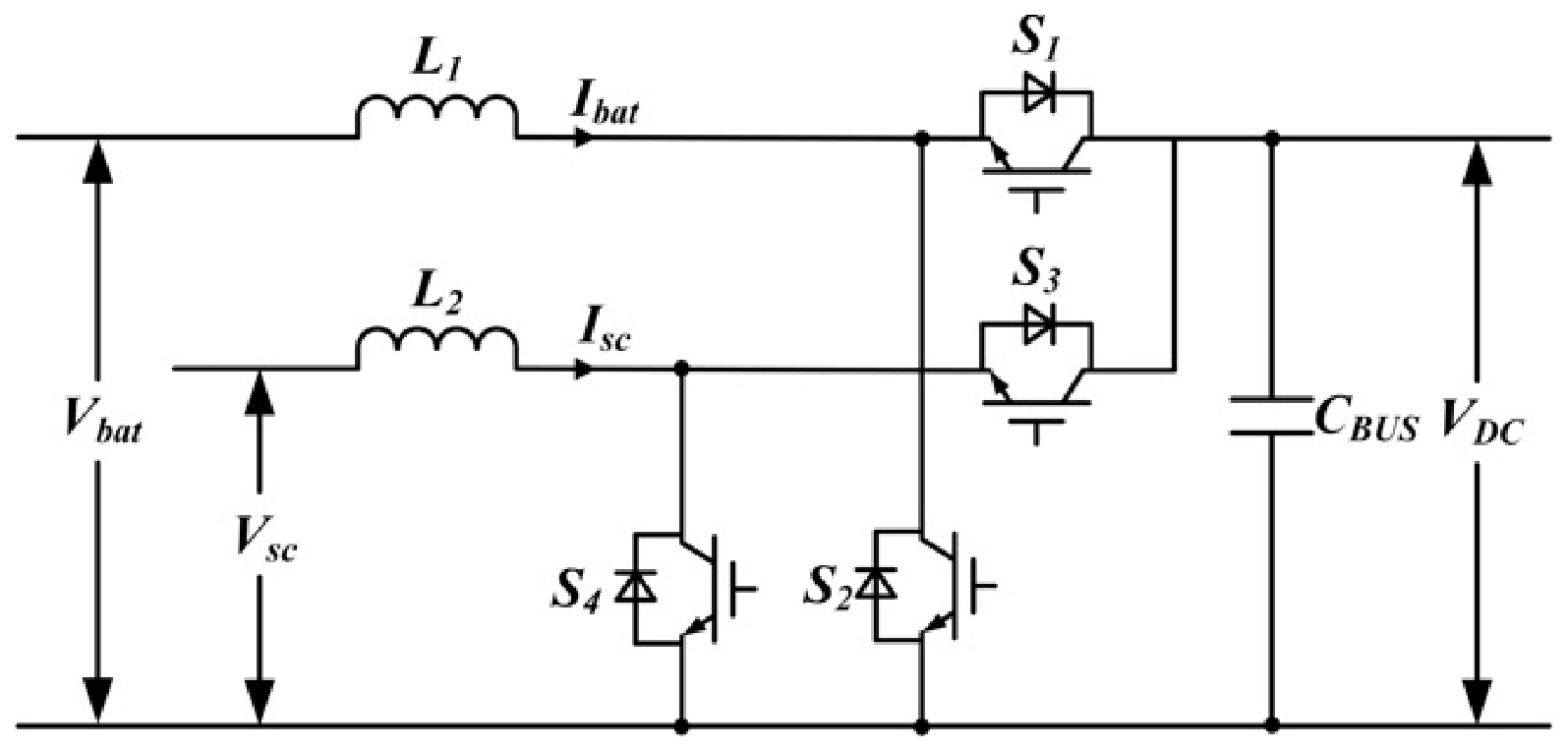
To smooth the fluctuating output power and maintain DC-bus stability, a battery–supercapacitor HESS is used in the direct-drive wave power generation system. Based on the complementary characteristics of the two storage devices, the battery branch is used to handle the low-frequency power component, while the supercapacitor branch is used to compensate for the high-frequency transient component. Bidirectional DC–DC converters are adopted as the power electronic interfaces between the storage branches and the DC bus. The overall topology of the HESS is shown in Figure 1.

2.3.1. Battery Model

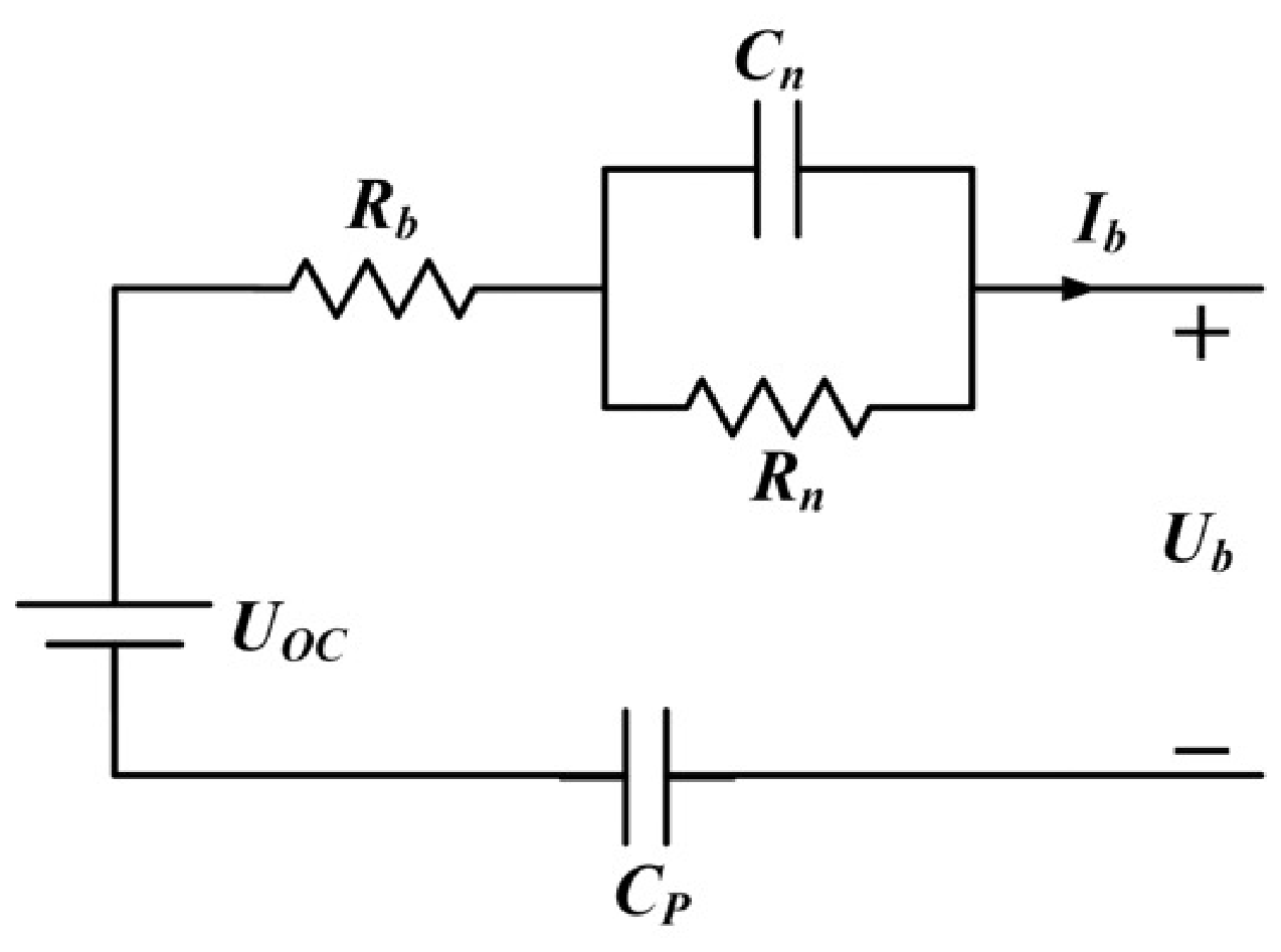
The PNGV equivalent circuit of the battery is shown in Figure 2. The model includes an open-circuit voltage source, an ohmic resistance, and polarization branches to describe the steady-state and transient electrical behavior of the battery.
The model equations are written as:
I b a t ( t ) = U n ( t ) R n + C n d U n ( t ) d t
U b a t ( t ) = U o c ( t ) + U p ( t ) I b a t ( t ) R b U b a t ( t )
I b a t ( t ) = C p d U p ( t ) d t
where Uoc is the open-circuit voltage, Rb is the ohmic internal resistance, Rn is the polarization resistance, Cn is the polarization capacitance, Cp is the capacitance used to describe the dynamic behavior of the battery, Un is the voltage across the polarization branch, Up is the voltage across Cp, Ib is the battery current, and Ub is the battery terminal voltage.
With the discharge current defined as positive, the battery power is calculated as:
P b a t ( t ) = U b a t ( t ) I b a t ( t )
where Pb > 0 denotes battery discharge and Pb < 0 denotes battery charge.

2.3.2. Supercapacitor Model

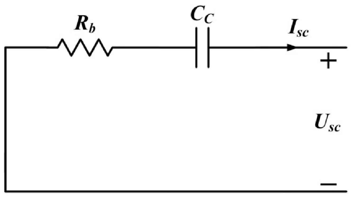
The equivalent circuit of the supercapacitor is shown in Figure 3. In the HESS, the supercapacitor is used to compensate for the high-frequency transient power component.
The model equations are written as:
U s c ( t ) = U c ( t ) + I s c ( t ) R ESR
I s c ( t ) = U c ( t ) R EPR + C c d U c ( t ) d t
where RESR is the equivalent series resistance, REPR is the equivalent parallel resistance, Cc is the supercapacitor capacitance, Uc is the capacitor voltage, Isc is the supercapacitor current, and Usc is the terminal voltage of the supercapacitor.
Since REPR is large, the leakage current is small over the simulation time scale considered in this study. Therefore, the leakage branch is neglected, and the simplified model is written as:
I s c ( t ) = C c d U c ( t ) d t .
The stored energy of the supercapacitor is expressed as:
W s c ( t ) = 1 2 C c U c 2 ( t ) .

3. EMD-Based Power Allocation and Control Strategy of the DDWEC with HESS

3.1. Generator-Side FCS-MPCC of the PMLG

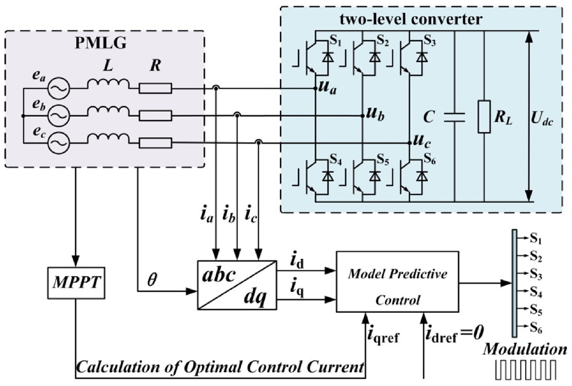
FCS-MPCC is used as the generator-side current control method to improve the current response of the PMLG under fluctuating wave excitation. The overall configuration of the generator-side FCS-MPCC is shown in Figure 4.
According to the dq-axis voltage equations of the PMLG, the continuous-time current dynamics used for prediction can be written as:
e d = R s i d ( t ) + L d d i d ( t ) d t π v ( t ) τ L q i q ( t ) + u d ( t ) e q = R s i q ( t ) + L q d i q ( t ) d t π v ( t ) τ L d i d ( t ) + u q ( t )
where ed and eq are the d-axis and q-axis back electromotive forces, id and iq are the stator currents, ud and uq are the dq-axis converter output voltages, Rs is the stator resistance, Ld and Lq are the d-axis and q-axis inductances, v(t) is the translator velocity, and τ is the pole pitch.
The current derivatives are discretized using the first-order Euler approximation:
d i d t i ( k + 1 ) i ( k ) T s
where Ts is the sampling period. The one-step-ahead prediction model of the PMLG currents is then obtained as:
i d ( k + 1 ) = ( 1 T s R s L d ) i d ( k ) + T s π v ( k ) τ L q L d i q ( k ) T s u d ( k ) L d i q ( k + 1 ) = T s π v ( k ) τ L q Ψ f + ( 1 T s R s L q ) i q ( k ) T s π v ( k ) τ L d L q i q ( k ) T s u d ( k ) L d .
For the surface-mounted PMLG considered in this study, the d-axis current reference was set to zero to reduce unnecessary d-axis current. Thus,
i d * ( k + 1 ) = 0 .
Based on the predicted currents, the generator-side FCS-MPCC cost function is defined as:
J = i d * ( k + 1 ) i d ( k + 1 ) + i q * ( k + 1 ) i q ( k + 1 ) .
To ensure safe operation, the current constraint is written as
i max i d i max i max i q i max .
Although the generator-side MPCC improves the current response of the PMLG, the electromagnetic power produced under irregular wave excitation still requires a power allocation stage before HESS-side control.

3.2. EMD-Based Power Allocation of the HESS

EMD was therefore used in this study as the power allocation method. It decomposes the HESS power command into components with different local time scales. The physical basis of this allocation lies in the complementary power and energy characteristics of the battery and supercapacitor. The relatively high energy density of the battery makes it suitable for the low-frequency component associated with slowly varying and longer-duration energy exchange. In contrast, the high power density, rapid charge–discharge response, and high cycle endurance of the supercapacitor make it suitable for the high-frequency component associated with short-duration transient power fluctuations [49,50]. Accordingly, the reconstructed low-frequency component is used as the battery power reference, whereas the high-frequency component is used as the supercapacitor power reference. This allocation reduces the exposure of the battery to rapid current variations while utilizing the supercapacitor for fast transient power compensation.

3.2.1. EMD-Based Decomposition of Fluctuating Power

In the proposed system, the electrical power generated by the PMLG is primarily delivered to the load through the common DC bus. The HESS does not absorb the entire generated power, but only compensates for the instantaneous power imbalance between the generated power and the load demand. Neglecting line loss and converter loss, the HESS power command is defined as:
P HESS ( t ) = P load ( t ) P wave ( t )
where Pload(t) is the load-side power demand and Pwave(t) is the electrical power generated by the direct-drive wave power generation system. When the generated wave power exceeds the load demand, the HESS absorbs the surplus power. When the generated power is lower than the load demand, the HESS supplies the power deficit.
The fluctuating power signal to be decomposed is defined as:
P ( t ) = P HESS ( t ) .
The local maxima and local minima of P′(t) are first identified. The upper envelope Pmax(t) and lower envelope Pmin(t) are then constructed by cubic spline interpolation. Their mean value is expressed as:
m ( t ) = P max ( t ) + P min ( t ) 2 .
By subtracting the envelope mean from the input signal, the local detail component is then obtained as:
r ( t ) = P ( t ) m ( t ) .
If r(t) satisfies the intrinsic mode function (IMF) criterion, it is extracted as an IMF component, denoted by imfi(t). Otherwise, the sifting process is repeated until the IMF criterion is satisfied. After the i-th IMF component is extracted, the residual signal is updated according to:
P ( t ) = P ( t ) imf i ( t ) .
This procedure is repeated until the residual becomes monotonic or contains no further oscillatory component. The fluctuating power signal is finally expressed as the sum of all IMF components and a residual term.

3.2.2. Frequency Boundary Determination and Power Reconstruction

After EMD, the frequency characteristics of each IMF component are estimated using the Hilbert transform. For the i -th IMF component imfi, the Hilbert transform is defined as:
H imf i ( t ) = 1 π P . V . + imf i ( τ ) t τ d τ
where P.V. is the Cauchy principal value.
The corresponding analytic signal is expressed as:
z i ( t ) = imf i ( t ) + j imf i ( t ) = a i ( t ) e j θ i ( t )
where ai(t) is the instantaneous amplitude and θi(t) is the instantaneous phase.
The instantaneous frequency of the i-th IMF component is obtained as:
f i ( t ) = 1 2 π d θ i ( t ) d t .
Based on the instantaneous-frequency distributions of the IMF components, each possible division between adjacent IMF components is evaluated as a candidate frequency boundary. For each candidate, a frequency-aliasing index is calculated according to the instantaneous-frequency crossings between neighboring IMF components. The candidate corresponding to the minimum nonzero index is automatically selected as the frequency boundary. A smaller index indicates weaker frequency aliasing and a clearer separation between the fast and slow power fluctuations. Based on the determined boundary, the low-frequency and high-frequency powers are reconstructed as follows:
P low ( t ) = i = n b N imf i ( t ) + res ( t ) ,
P high ( t ) = i = 1 n b = 1 imf i ( t ) .
Accordingly, the reference powers of the battery branch and the supercapacitor branch are defined as:
P b a t , ref ( t ) = P low ( t ) ,
P s c , ref ( t ) = P high ( t ) .
where the low-frequency component is assigned to the battery branch and the high-frequency component is assigned to the supercapacitor branch.
The frequency-aliasing index is used to select the boundary with the weakest instantaneous-frequency overlap between adjacent IMF components. This criterion reduces the influence of mode mixing on the power-allocation boundary by avoiding the separation of strongly overlapping neighboring modes. The low-frequency and high-frequency power references are reconstructed by directly summing the selected IMF components at their original sampling instants. Therefore, the reconstructed power components retain the original time coordinates without introducing an additional fixed group delay. EEMD and CEEMDAN are noise-assisted extensions that can further improve modal separation and reconstruction completeness [51,52]. Endpoint-extension approaches based on mirror expansion and signal prediction have also been developed to improve the boundary treatment of EMD [53]. Considering the computational efficiency required by the power-allocation framework, classical EMD combined with the automatic frequency-aliasing-based boundary-selection criterion was adopted in this study.

3.3. MPC-Based Control Strategy of the HESS

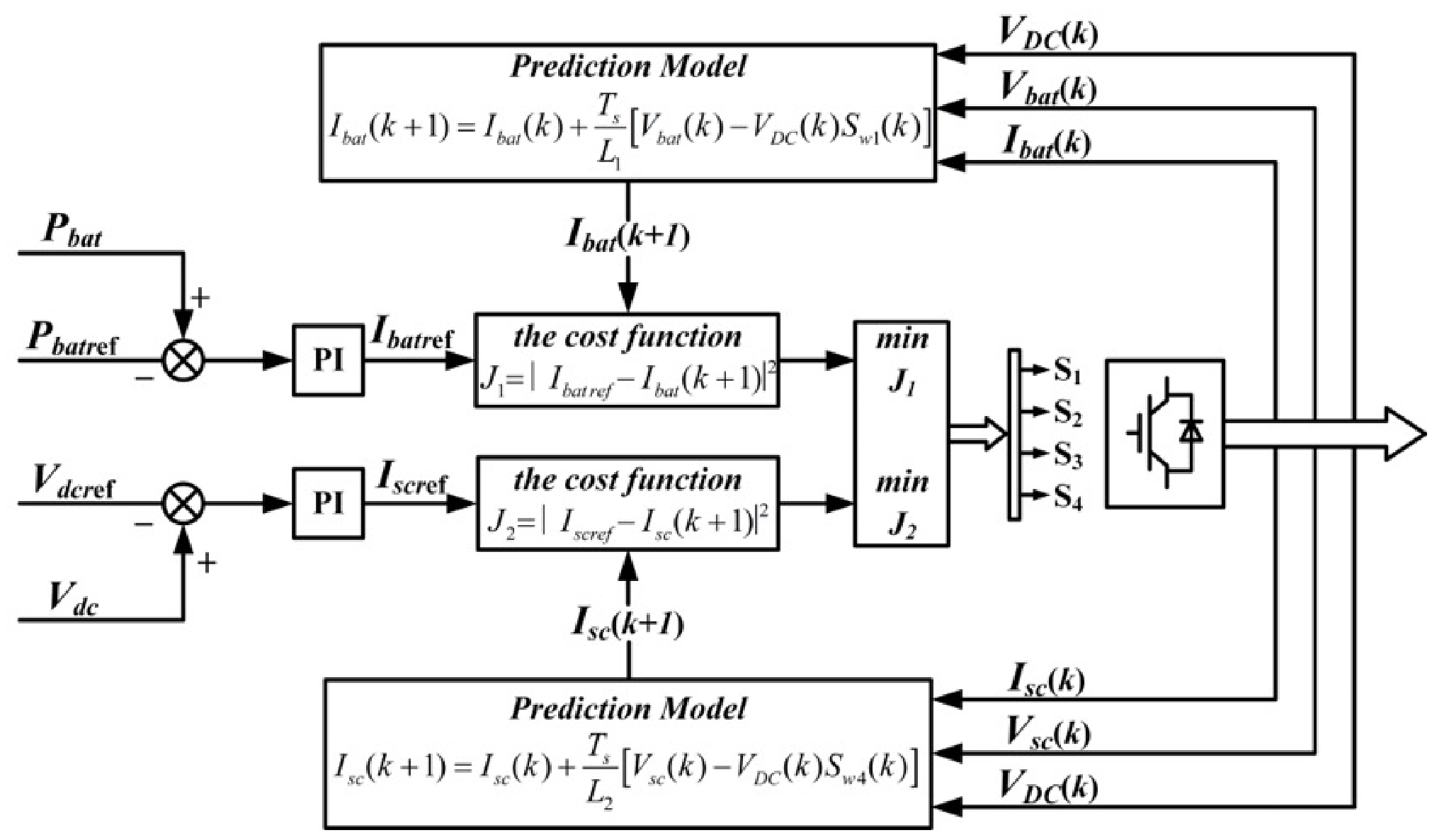
Based on the EMD-based power allocation, the HESS-side controllers are designed to track the assigned power commands and regulate the DC-bus voltage. The battery branch tracks the low-frequency power reference through a power outer loop and an MPC current inner loop. For the supercapacitor branch, the current reference is generated by the DC-bus voltage regulation term, and the resulting current command is tracked by an MPC current inner loop. The overall control structure is shown in Figure 5.

3.3.1. Battery-Branch Control

The battery branch is used to track the low-frequency power reference Pbat,ref obtained from the EMD-based allocation. The power error is processed by a PI regulator to generate the battery current reference:
I b a t , ref ( k ) = G P I , b a t ( P b a t , ref ( k ) P b a t ( k ) )
where Pb(k) is the actual battery power and GPI,bat is the battery-side PI regulator.
Based on the battery-branch prediction model, the battery current at the next sampling instant is predicted as:
I b a t ( k + 1 ) = I b a t ( k ) + T s L 1 ( V b a t ( k ) V d c ( k ) S w 1 ( k ) )
where Ibat(k) is the battery current, Vbat(k) is the battery terminal voltage, Vdc(k) is the DC-bus voltage, L1 is the battery-branch inductance, TS is the sampling period, and Sw1(k) is the candidate switching state.
The battery-side cost function is defined as:
J 1 = [ I b a t , ref ( k ) I b a t ( k + 1 ) ] 2 .
The switching state that minimizes J1 is selected and applied in the next control interval.
The battery-side MPC prioritizes the tracking of the current reference generated from the allocated battery power command, while the influence of rapid power variations on the battery is mitigated primarily through the preceding EMD-based power-allocation stage. EMD adaptively decomposes the fluctuating HESS power command into IMF components with different local time scales. Based on the automatically determined boundary, the slowly varying low-frequency IMFs and residual component are reconstructed as the battery power reference, whereas the rapidly fluctuating high-frequency IMFs are reconstructed as the supercapacitor power reference. Because the battery current reference is generated from the reconstructed low-frequency power component, high-frequency fluctuations are prevented from entering the battery current-control loop. This produces a smoother battery current command and reduces rapid current variations and frequent charge–discharge transitions.

3.3.2. Supercapacitor-Branch Control

The supercapacitor branch is used to compensate for fast power fluctuations and support DC-bus voltage regulation. Owing to its fast dynamic response, the outer-loop control objective of the supercapacitor branch is selected as DC-bus voltage regulation. The voltage error is defined as:
e d c ( k ) = V d c , ref ( k ) V d c ( k ) .
The supercapacitor current reference is generated by the voltage outer-loop PI controller as:
I s c , ref ( k ) = G P I , s c ( V d c , ref ( k ) V d c ( k ) )
where GPI,sc is the supercapacitor-side PI regulator.
Based on the supercapacitor-branch prediction model, the supercapacitor current at the next sampling instant is predicted as:
I s c ( k + 1 ) = I s c ( k ) + T s L 2 ( V s c ( k ) V d c ( k ) S w 4 ( k ) )
where Isc(k) is the supercapacitor current, Vsc(k) is the supercapacitor terminal voltage, L2 is the supercapacitor-branch inductance, and Sw4(k) is the candidate switching state.
The supercapacitor-side cost function is defined as:
J 2 = [ I s c , ref ( k ) I s c ( k + 1 ) ] 2 .
The switching state that minimizes J2 is selected and applied in the next control interval.

4. Results

4.1. Simulation Setup

To verify the proposed coordinated control strategy, a Simulink model of DDWEC with battery–supercapacitor HESS was established. The model includes the PMLG-based WEC unit, the generator-side FCS-MPCC, the common DC bus, and the battery–supercapacitor HESS. The main simulation parameters are listed in Table 1.

4.2. Generator-Side MPCC Performance

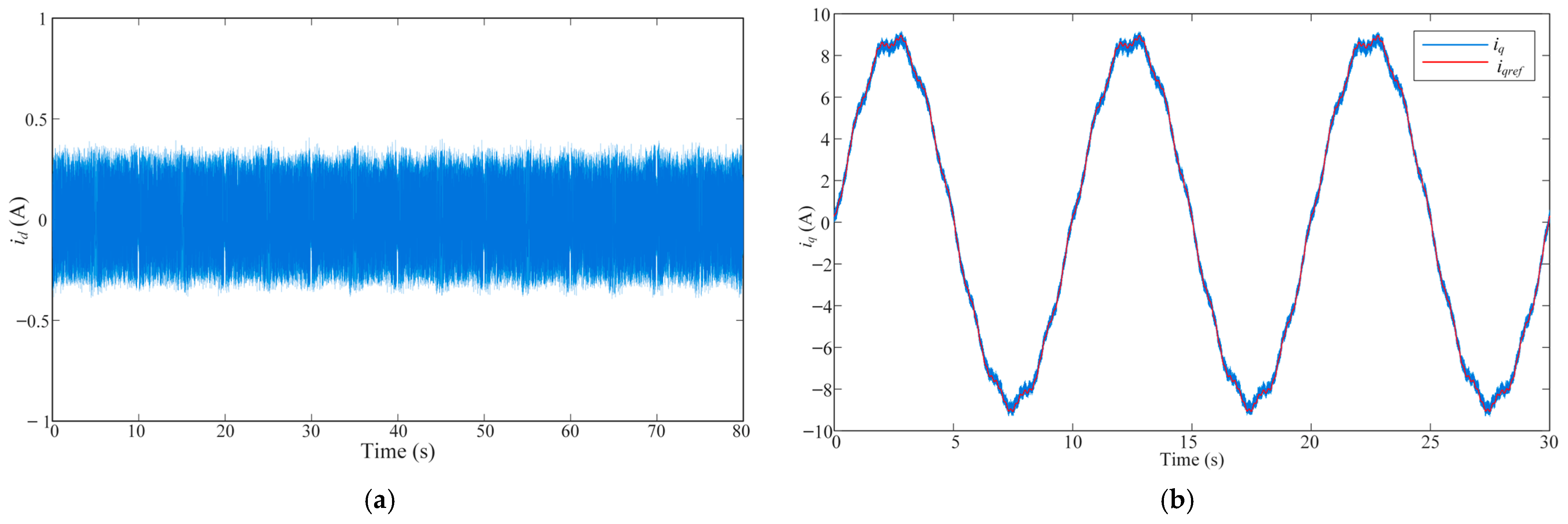
The generator-side control performance was evaluated by the d-axis and q-axis current responses of the PMLG, as shown in Figure 6.
As shown in Figure 6a, the d-axis current remained close to zero during the simulation, with an RMS tracking error of 0.174 A. Figure 6b shows that the q-axis current followed its reference under irregular wave excitation, with an RMS tracking error of 0.184 A. These results indicate that the generator-side FCS-MPCC provides stable current regulation for the PMLG.
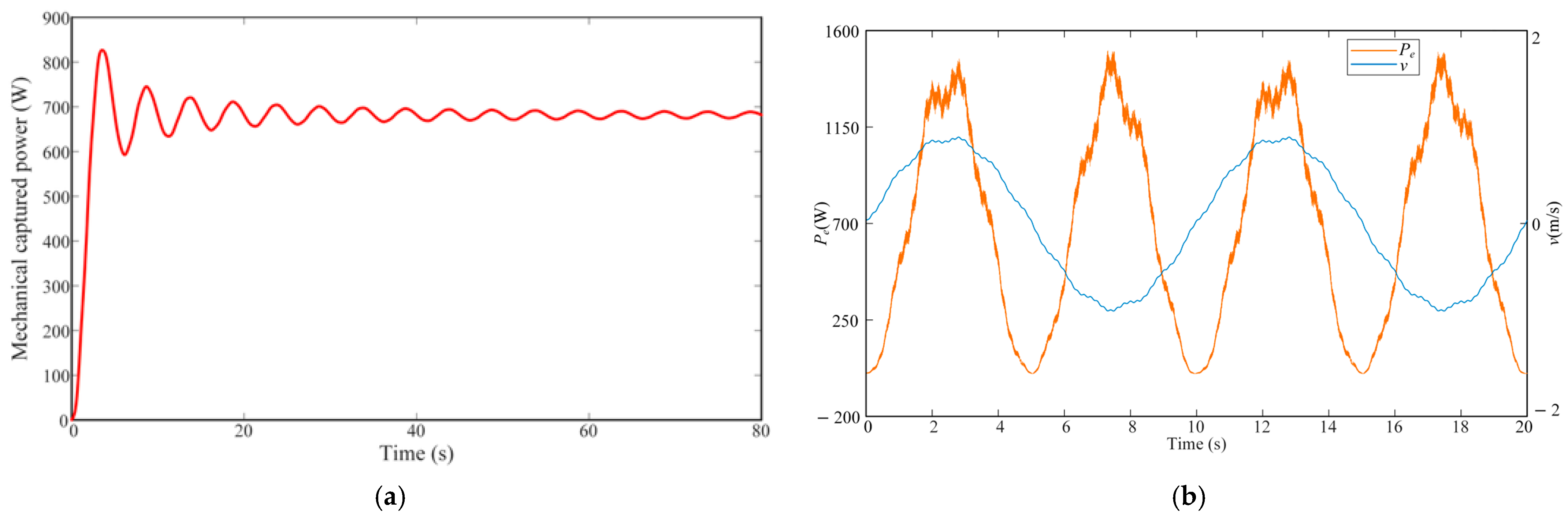
Mechanical and electromagnetic power characteristics of the PMLG are shown in Figure 7.
As shown in Figure 7a, the mechanical captured power increases during the initial transient stage and then enters a stable oscillatory state. Figure 7b shows that the electromagnetic power varies with the reciprocating translator velocity, reflecting the pulsating power characteristic of the direct-drive PMLG. The resulting electromagnetic power signal is subsequently used as the input for the EMD-based HESS power allocation.

4.3. EMD-Based Power Allocation Results and LPF Comparison

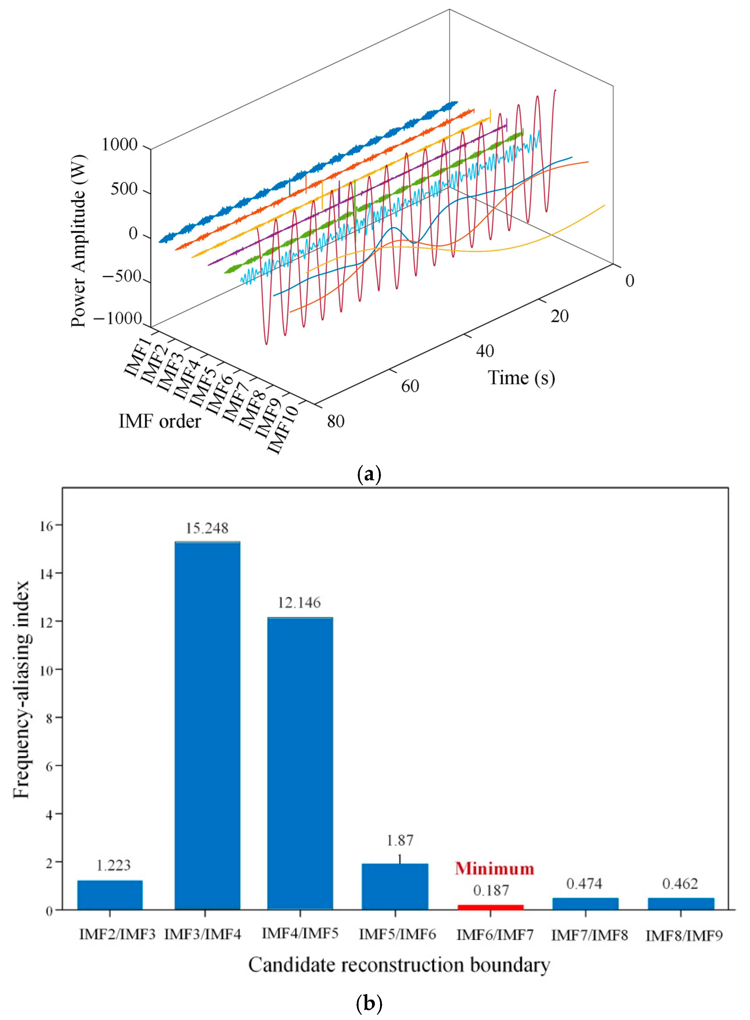
The EMD decomposition result of the fluctuating power signal is presented in Figure 8a. Each colored curve represents the temporal evolution of one IMF component, and the three axes denote time, IMF order, and power amplitude, respectively. IMF1–IMF6 exhibit densely distributed and rapidly varying oscillations over the 0–80 s interval, indicating that these components mainly contain short-time-scale power fluctuations. From IMF7 to IMF10, the oscillations become progressively more widely spaced, and the corresponding components represent medium- to long-time-scale power variations. The IMF components exhibit different power-amplitude ranges, and IMF order primarily reflects the variation in their oscillation time scales.
To determine the reconstruction boundary quantitatively, the frequency-aliasing indices of the valid candidate boundaries are compared in Figure 8b. The minimum positive index was 0.187 at the IMF6/IMF7 boundary, compared with 1.871 at IMF5/IMF6 and 0.474 at IMF7/IMF8. According to the criterion described in Section 3.2.2, a smaller index indicates weaker frequency aliasing between neighboring IMF components. Therefore, the boundary between IMF6 and IMF7 is selected automatically. Accordingly, IMF1–IMF6 are combined to form Phigh, with IMF7–IMF10 together with the residual form Plow.
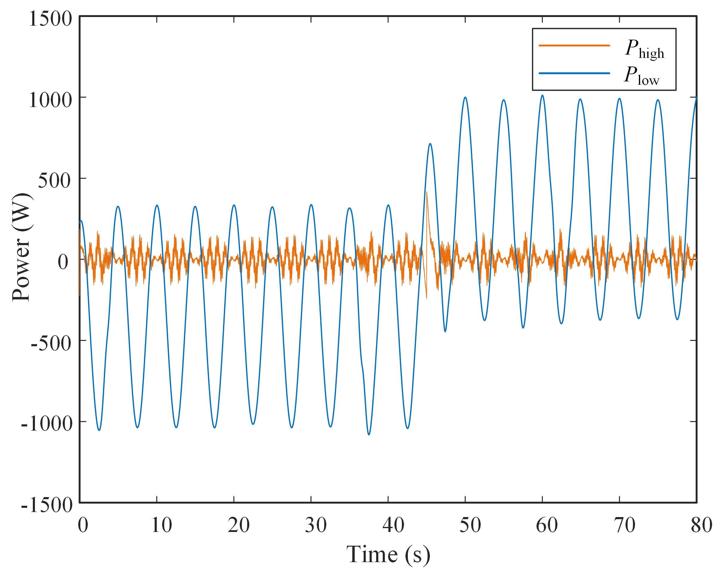
Based on the IMF6/IMF7 boundary automatically selected in Figure 8b, the reconstructed Phigh and Plow are shown in Figure 9. The low-frequency component presents a smooth and slowly varying waveform and contains the main energy variation of the fluctuating power. In contrast, the high-frequency component oscillates around zero and represents short-time power fluctuations. These reconstructed components are consistent with the time-scale hierarchy presented in Figure 8a and the quantitative boundary selection shown in Figure 8b.
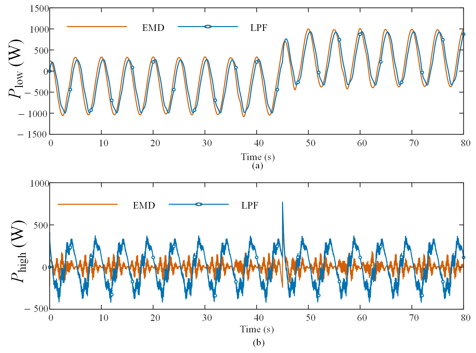
Figure 10 compares the EMD- and LPF-based power-allocation results over the same 80 s record. A causal first-order LPF was adopted as the conventional comparison method. The LPF output was assigned to Plow, while the difference between the original power and the LPF output was assigned to Phigh. For a fair comparison, all system and controller settings were kept unchanged. The cutoff frequency was determined from the characteristic frequencies of the two adjacent IMFs on either side of the automatically selected EMD boundary, giving fc = 0.4457 Hz. Low-frequency leakage was calculated as the proportion of the spectral energy below fc in Phigh relative to its total spectral energy. A lower leakage value indicates that less slowly varying power remains in the supercapacitor power command.
As shown in Table 2, the proposed EMD method reduced the standard deviation of Phigh by 72.47% and the low-frequency leakage in Phigh by 93.48% compared with LPF. The low leakage value of 6.07% shows that the EMD-based high-frequency component mainly contains rapidly varying power, whereas the value of 93.14% for LPF indicates that a large amount of slowly varying power remains in its high-frequency component. In addition, the causal LPF produced an additional lag of 0.314 s. After the load change at 45 s, EMD reduced the maximum DC-bus voltage deviation by 11.94%. These results show that EMD provides clearer power separation and improves the DC-bus response during the load change.

4.4. Battery and Supercapacitor Control Performance

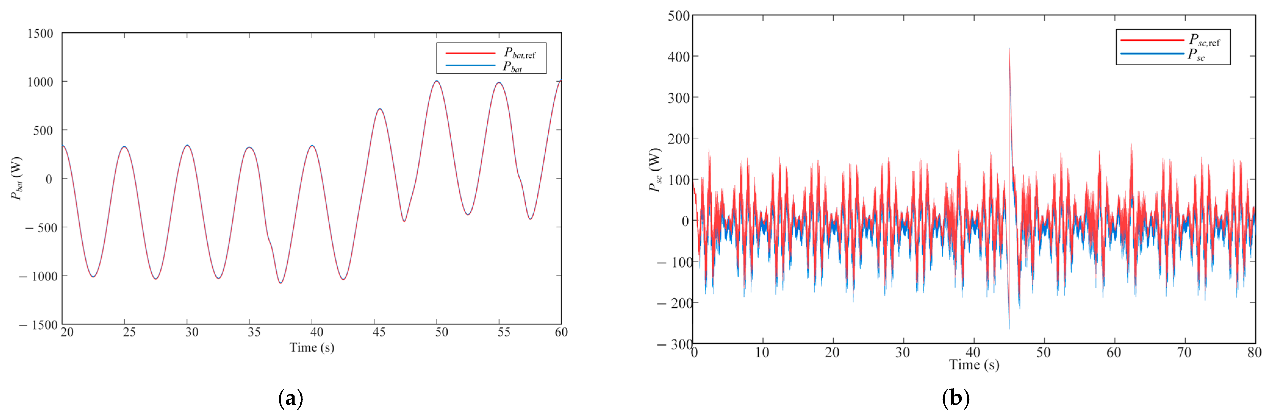
The HESS-side control performance was evaluated from the power and current responses of the battery and supercapacitor branches. The power tracking results are shown in Figure 11.
As shown in Figure 11a, the battery power follows the low-frequency power reference generated by the EMD-based allocation, indicating that the battery branch executes the energy-buffering command. Figure 11b shows that the supercapacitor power varies more rapidly around zero, which is consistent with its role in compensating fast power fluctuations. The actual power follows the main fluctuation trend of the reference signal, indicating that the supercapacitor branch provides the required fast compensation.
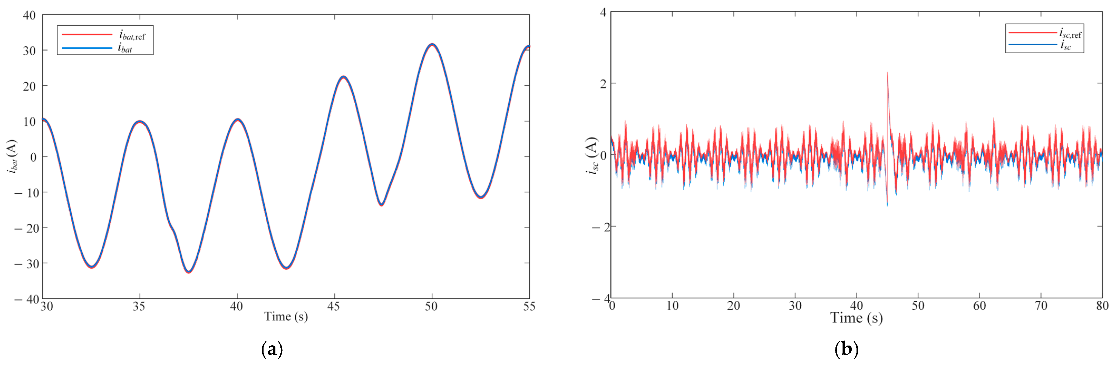
The current tracking results of the storage branches are shown in Figure 12.
As shown in Figure 12a, the battery current follows its reference with a relatively smooth waveform. This behavior is consistent with the role of the battery branch in handling the low-frequency power component generated by the EMD-based allocation. Figure 12b shows the current tracking response of the supercapacitor branch. Compared with the battery current, the supercapacitor current contains faster variations, which is consistent with its function of compensating rapid power fluctuations and supporting DC-bus voltage regulation. The actual current follows the main variation trend of the reference current after the initial transient.

4.5. Load Power Condition and DC-Bus Voltage Stabilization

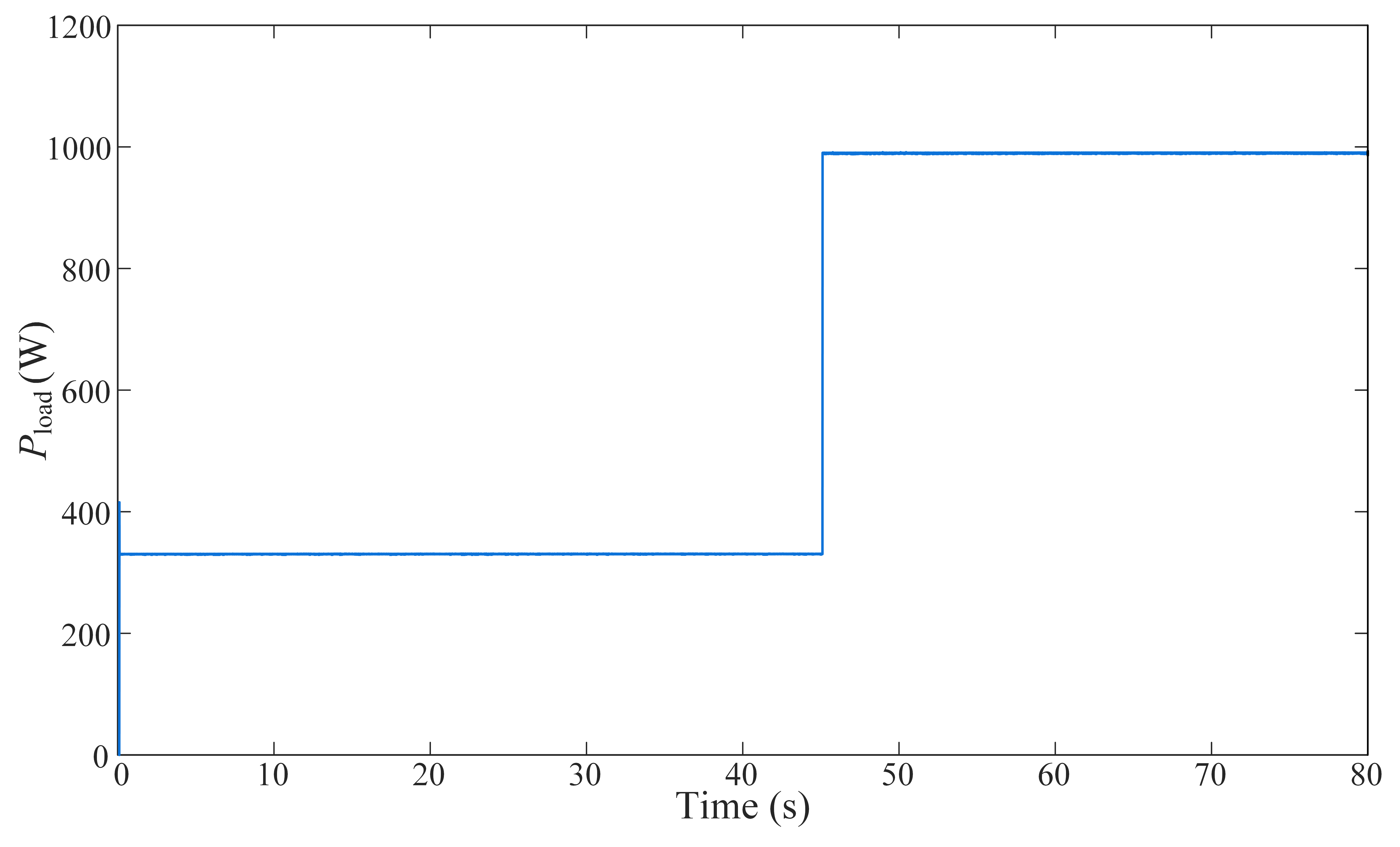
The load power profile used in the simulation is shown in Figure 13. As shown in Figure 13, the load power was approximately 330 W from 0 s to 45 s and then increased to approximately 990 W after 45 s.
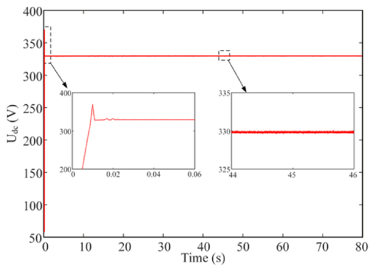
As shown in Figure 14, the DC-bus voltage rose during the startup stage and then converged to the 330 V reference. A short transient overshoot appeared at the beginning of the simulation. The maximum DC-bus voltage deviation during this transient was 39.72 V, and the voltage recovered to within ±1% of its reference value within approximately 0.011 s. During the load transition at 45 s, the maximum voltage deviation was only 0.43 V, and the DC-bus voltage remained within the ±1% band. The enlarged view further shows that the voltage fluctuation remained small under the fluctuating power condition.

4.6. Quantitative Summary of Simulation Results

To further evaluate the proposed coordinated control strategy, the key quantitative indices obtained from the simulation are summarized in Table 3.
Table 3. Key performance indices of the proposed control strategy.
ItemIndexValue
Generator-side current controlRMS error of iq tracking0.184 A
RMS value of id0.174 A
Electromechanical conversionMean electromagnetic power682.0 W
EMD-based power allocationStandard deviation of Plow/Phigh579.2/56.4 W
Battery power trackingRMS error of Pbat3.93 W
Supercapacitor power trackingRMS error of Psc14.63 W
HESS current trackingRMS error of ibat/isc0.099/0.081 A
DC-bus voltage regulationStd. of Vdc after transient0.108 V
The quantitative indices in Table 3 provide an overall evaluation of the proposed coordinated control strategy. The RMS errors of the q-axis and d-axis currents were 0.184 A and 0.174 A, respectively, indicating stable generator-side current regulation. The mean electromagnetic power of 682.0 W characterizes the average electromechanical output under the considered irregular-wave condition. The standard deviations of Plow and Phigh were 579.2 W and 56.4 W, respectively, quantifying the different variation levels of the reconstructed slow and fast power components. The RMS power-tracking errors of the battery and supercapacitor branches were 3.93 W and 14.63 W, while their RMS current-tracking errors were 0.099 A and 0.081 A, respectively. These indices quantify the ability of the two storage branches to follow their assigned power and current references. After the initial transient, the standard deviation of the DC-bus voltage was 0.108 V, corresponding to approximately 0.033% of the 330 V reference, which indicates stable DC-bus voltage regulation under fluctuating power conditions.

4.7. Experimental Validation

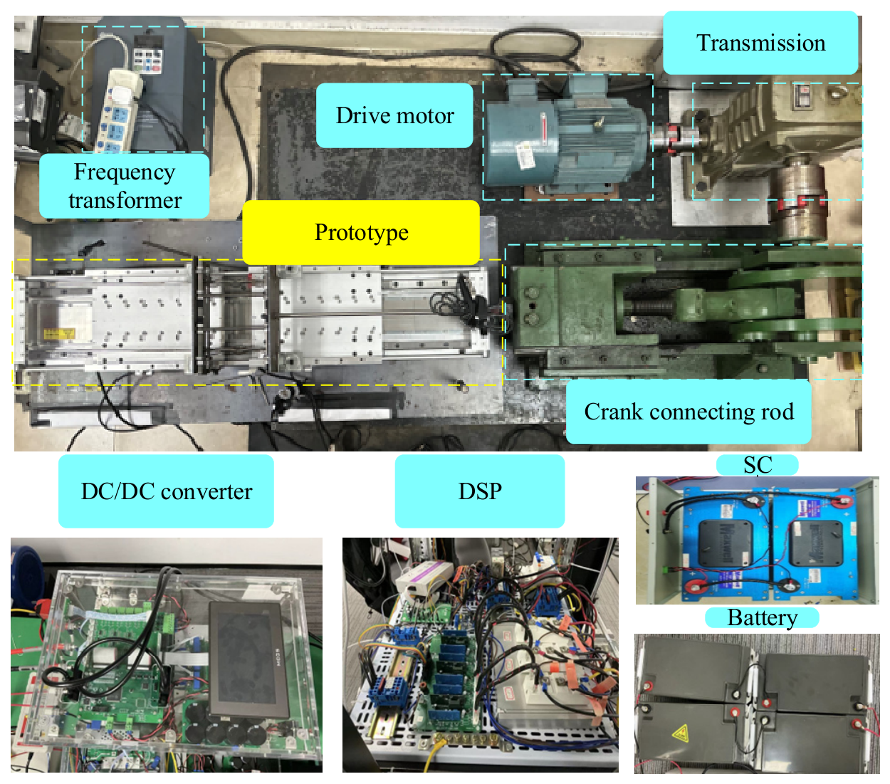
To supplement the simulation results, a laboratory-scale experimental platform was established for the DDWEC with a battery–supercapacitor HESS, as shown in Figure 15. The hardware mainly consisted of a wave power generation emulator, a permanent magnet linear generator (PMLG), a three-phase half-bridge rectifier, a battery, a supercapacitor, two bidirectional DC–DC converters, and a DC load. The control system was implemented using a DSP controller and a rapid-control-prototyping controller. The wave power generation emulator consisted of an induction motor, a frequency converter, a gearbox, a crank–connecting-rod mechanism, and the PMLG. The output of the PMLG was connected to the common DC bus through the three-phase half-bridge rectifier. The battery and supercapacitor were interfaced with the DC bus through their respective bidirectional DC–DC converters. The DSP controller was used to implement the generator-side control algorithm, whereas a rapid-control-prototyping controller was employed for the control of the hybrid energy storage system.
The PMLG was a TLM160-B0954SP-1-0300-E110 (Dongguan Aipusi Automation Technology Co., Ltd., Dongguan, China). The mechanical wave emulator employs a gearbox with a reduction ratio of 25 and a crank–connecting-rod mechanism with a connecting-rod length of 360 mm. The DC-bus voltage was measured using an LV25-P voltage transducer (LEM International SA, Meyrin, Switzerland) with a measurement range of 10–500 V and an accuracy of ±0.9%, while the electrical signals were acquired using a 16-bit AD7656 (Nanjing Yanxu Electrical Technology Co., Ltd., Nanjing, China) data-acquisition module with a bipolar input range of ±10 V. The generator-side control algorithm was implemented using a YXDSP-F28335 DSP (Nanjing Yanxu Electrical Technology Co., Ltd., Nanjing, China) controller, whereas the HESS-side MPC was implemented using a YXSPACE-SP2000 rapid-control-prototyping controller (Nanjing Yanxu Electrical Technology Co., Ltd., Nanjing, China) based on a TMS320F28377 processor (Texas Instruments Incorporated, Dallas, TX, USA). The three-phase half-bridge rectifier employs FF50R12RT4 IGBT modules (Infineon Technologies AG, Neubiberg, Germany) rated at 1200 V/50 A and a TX-DA102D6 six-channel PWM driver (Beijing LMY Electronics Co., Ltd., Beijing, China).
The main parameters of the laboratory-scale PMLG and the wave power generation emulator are summarized in Table 4. The simulation model and the laboratory prototype represent PMLGs with different physical dimensions and rated parameters. Therefore, the simulation controller used the parameters listed in Table 1, whereas the experimental controller was parameterized using the actual prototype parameters listed in Table 4. Although the parameter values are different, the mathematical model, control algorithm, and control objectives remain unchanged.
The laboratory PMLG used sintered Nd–Fe–B permanent magnets of grade N42SH. At 20 °C, the nominal remanent magnetic flux density Br was 1.27–1.33 T, the normal coercivity HcB was 0.923–1.035 MA/m, the intrinsic coercivity HcJ was at least 1.671 MA/m, and the maximum energy product (BH)max was 310–342 kJ/m3. The second-quadrant B–H curve decreased approximately linearly from B ≈ 1.30 T at H = 0 toward B = 0 as the reverse magnetic field approached HcB.
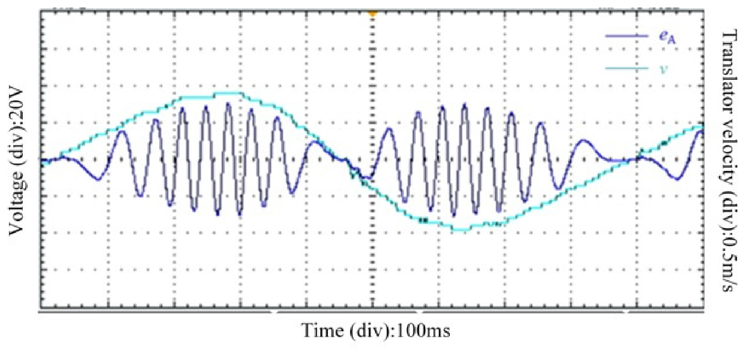
The experimental results were used to verify the main control functions investigated in the simulations. Figure 16 verifies the electromechanical response of the PMLG through the measured relationship between the translator velocity and the phase-A back-EMF. Figure 17 evaluates the tracking of the battery and supercapacitor current references generated from the EMD-based power commands. Figure 18 further evaluates the coordinated operation of the two storage branches and the regulation of the DC-bus voltage.
Figure 16 shows the measured phase-A back-EMF and translator velocity of the PMLG. As the magnitude of the translator velocity increased, both the amplitude and electrical frequency of the phase-A back-EMF increased. Near the reversal points of the reciprocating motion, the translator velocity approached zero and the back-EMF correspondingly decreased. This relationship is consistent with the electromagnetic induction characteristics of the PMLG and confirms the electromechanical response of the experimental platform under reciprocating motion.
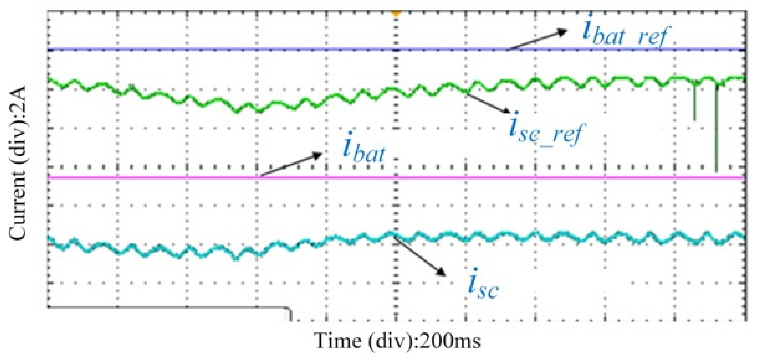
Figure 17 compares the reference and measured currents of the battery and supercapacitor branches. The peak-to-peak variations of the battery reference and measured currents were approximately 0.04 A and 0.02 A, respectively. Excluding the two narrow downward pulses, the peak-to-peak variations of the supercapacitor reference and measured currents were approximately 0.55 A and 0.44 A, respectively. The substantially smaller current variation in the battery branch indicates that the slowly varying power component is assigned to the battery, whereas the larger variation in the supercapacitor branch reflects its response to the rapidly fluctuating power component. The low-frequency and high-frequency power components generated by the EMD-based allocation were separately supplied as the reference power commands for the battery and supercapacitor control branches. The branch controllers converted the two power commands into their corresponding current references. The measured battery and supercapacitor currents followed their respective references, demonstrating that the two HESS branches can effectively execute the EMD-based allocated power commands under MPC control.
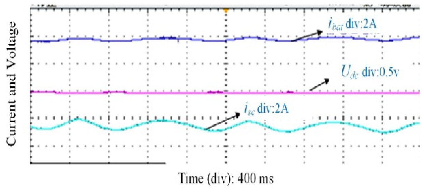
Figure 18 shows the battery current, supercapacitor current, and DC-bus voltage measured simultaneously under coordinated HESS operation. According to the oscilloscope vertical scales, the peak-to-peak variations of the battery and supercapacitor currents were approximately 0.4 A and 1.4 A, respectively. The substantially smaller variation in the battery current is consistent with its response to the slowly varying power component, whereas the larger supercapacitor current variation reflects its response to the rapidly fluctuating power component. Meanwhile, the DC-bus voltage was maintained around its reference value with a fluctuation of approximately ±2 V. Together with the reference-current tracking results in Figure 17, these results demonstrate that the two storage branches perform their respective power-allocation functions while maintaining the DC-side power balance and voltage regulation.

4.8. Limitations

The present study has several limitations. The PMLG was represented by a control-oriented model in which magnetic saturation, core losses, cogging force, and higher-order harmonics are neglected, while the experimental validation was conducted under the operating conditions achievable with the laboratory wave power generation emulator and focused on the back-EMF characteristics, the current-tracking performance of the battery and supercapacitor branches, and DC-bus voltage regulation. Future work will extend the experimental operating conditions, refine the PMLG model, and experimentally compare classical EMD with EEMD and CEEMDAN in terms of mode separation, endpoint behavior, phase response, and computation time.

5. Conclusions

This study proposed a control strategy that combines generator-side FCS-MPCC, EMD-based power allocation, and HESS-side MPC for a PMLG-based direct-drive wave power generation system. The EMD reconstruction boundary is selected automatically using the frequency-aliasing index, without requiring a fixed cutoff frequency.
Under the same 80 s input and control settings, the proposed EMD method reduced the standard deviation of the high-frequency power component from 204.9 W with LPF to 56.4 W and reduced its low-frequency leakage from 93.14% to 6.07%. The LPF introduced an additional lag of 0.314 s. After the load change at 45 s, the maximum DC-bus voltage deviation decreased from 0.484 V with LPF to 0.426 V with EMD. These results show that EMD provides clearer power separation and better DC-bus response. The rapidly changing power is assigned to the supercapacitor, while the battery receives a smoother power command, which reduces rapid battery-current changes and frequent charging and discharging.
The experimental results show that the battery and supercapacitor currents followed their references. Their peak-to-peak variations were approximately 0.4 A and 1.4 A, respectively, while the DC-bus voltage fluctuation remained within approximately ±2 V. These results confirm that the two storage branches can carry out the assigned power commands while maintaining the DC-bus voltage. Future work will consider battery SOC, current constraints, and battery degradation in the HESS-side MPC and conduct system-level experiments under irregular-wave conditions.

Author Contributions

Conceptualization, Z.Z. and Y.S.; methodology, Z.Z. and M.C.; software, Z.Z., J.Y. and W.Q.; validation, Z.Z.; formal analysis, Z.Z., Y.S. and R.G.; investigation, Z.Z. and Y.S.; resources, M.C. and L.H.; data curation, Y.S., J.Y. and W.Q.; writing—original draft preparation, Z.Z.; writing—review and editing, M.C.; visualization, Z.Z.; supervision, M.C.; project administration, M.C.; funding acquisition, M.C. and L.H. All authors have read and agreed to the published version of the manuscript.

Funding

This work was supported in part by the National Natural Science Foundation of China under grant 52407041, in part by the Key Project of Ocean Institute of Southeast University Rudong under grant KP202604, and in part by the Scientific Research Fund of Nanjing Institute of Technology under grant YKJ202453.

Data Availability Statement

The data presented in this study are available on request from the corresponding author.

Conflicts of Interest

The authors declare no conflicts of interest.

References

  1. Huang, L.; Yang, J.; Hu, M. Wave prediction and predictive control approach for efficiency optimization in wave energy conversion systems: A review. Electr. Power Syst. Res. 2026, 254, 112613. [Google Scholar] [CrossRef] [Scilit]
  2. Zhang, Z.; Wu, B.; Lu, Q.; Xu, W. Novel Linear Generator Concepts and Topologies for Wave Energy Conversion Systems: A Review. In Proceedings of the 2021 13th International Symposium on Linear Drives for Industry Applications, Wuhan, China, 1–3 July 2021; IEEE: New York, NY, USA, 2021; pp. 1–6. [Google Scholar]
  3. Ma, L.; Huang, X.; Li, L.; Fu, Q.; Wang, C.; Wang, X. Designing a Power Supply System for an Amphibious Robot Based on Wave Energy Generation. J. Mar. Sci. Eng. 2025, 13, 1466. [Google Scholar] [CrossRef] [Scilit]
  4. Gao, Y.; Lyu, Y.; Huang, H.; Qu, R. Review of Flux Modulation Linear Permanent Magnet Machines. IEEE Trans. Transp. Electrif. 2025, 11, 2629–2647. [Google Scholar] [CrossRef] [Scilit]
  5. Tan, J.; Wang, X.; Polinder, H.; Jarquin Laguna, A.; Miedema, S.A. Downsizing the Linear PM Generator in Wave Energy Conversion for Improved Economic Feasibility. J. Mar. Sci. Eng. 2022, 10, 1316. [Google Scholar] [CrossRef] [Scilit]
  6. Pan, Z.; Zhao, J.; Wei, K.; Shen, Y. Design and Analysis of Permanent Magnet Arc-Linear Motor Having Different Stator-Permanent Magnet Arrangements. IEEE Trans. Plasma Sci. 2025, 53, 430–438. [Google Scholar] [CrossRef] [Scilit]
  7. Farrok, O.; Islam, R.; Sheikh, R.I.; Guo, J.; Zhu, J.G. A Split Translator Secondary Stator Permanent Magnet Linear Generator for Oceanic Wave Energy Conversion. IEEE Trans. Ind. Electron. 2018, 65, 7600–7608. [Google Scholar] [CrossRef] [Scilit]
  8. Pan, Z.; Cai, J.; Zhao, J.; Wei, K.; Chen, H. Topology Design and Performance Analysis of a Circular/Axis Bidirectional Modular Permanent Magnet Arc Linear Motor. IEEE Trans. Ind. Electron. 2026, 73, 5269–5280. [Google Scholar] [CrossRef] [Scilit]
  9. Li, X.; Shi, B.; Huang, W.; Wu, X.; Xu, W. Development of a High-Thrust Dual-Mover Transverse-Flux Linear Oscillatory Machine With Spoke PMs Embedded on Mover Yoke. IEEE Trans. Transp. Electrif. 2025, 11, 8617–8628. [Google Scholar] [CrossRef] [Scilit]
  10. Baker, N.J.; Raihan, M.A.H.; Almoraya, A.A. A Cylindrical Linear Permanent Magnet Vernier Hybrid Machine for Wave Energy. IEEE Trans. Energy Convers. 2019, 34, 691–700. [Google Scholar] [CrossRef] [Scilit]
  11. Fu, D.; Wu, K.; Zheng, P.; Yu, Q.; Wu, X. Force Modeling and Analysis of a Tube Flux-Switching Transverse-Flux Permanent Magnet Linear Motor. IEEE Trans. Ind. Appl. 2022, 58, 4575–4586. [Google Scholar] [CrossRef] [Scilit]
  12. Li, X.; Jiang, M.; Xu, W.; Wu, T.; Zhang, D. Design and Test of a Less-Rare-Earth Stator-Magnet Moving-Iron Transverse-Flux Linear Oscillatory Machine for Reciprocating Drive. IEEE Trans. Ind. Electron. 2024, 71, 2831–2841. [Google Scholar] [CrossRef] [Scilit]
  13. Ling, Z.; Yuan, Y.; Zhao, W.; Zeng, Y.; Xu, M.; Ji, J.; Gu, Y. Permeance Reconfiguration in Flux Modulation Permanent Magnet Machines With Transcription Waveform Method. IEEE Trans. Energy Convers. 2026. early access. [Google Scholar] [CrossRef] [Scilit]
  14. Nie, R.; Si, J.; Wang, P.; Li, Z.; Liang, J.; Gan, C. Optimization Design of a Novel Permanent Magnet Linear-Rotary Generator for Offshore Wind-Wave Combined Energy Conversion Based on Multi-Attribute Decision Making. IEEE Trans. Energy Convers. 2024, 39, 1583–1600. [Google Scholar] [CrossRef] [Scilit]
  15. Xia, T.; Li, Z.; Liu, H.; Zhang, Y.; Yu, H. Design of a Magnetic Field Modulated Screw Containing Composite Rotors for Wave Energy Conversion. IEEE Trans. Power Electron. 2024, 39, 13869–13878. [Google Scholar] [CrossRef] [Scilit]
  16. Ling, Z.; Xu, W.; Zhao, W.; Meng, S.; Xu, M. Design and Analysis of a Field Modulated Magnetic Screw Without Permanent Magnet Skewing. IEEE Trans. Ind. Electron. 2025, 72, 8798–8809. [Google Scholar] [CrossRef] [Scilit]
  17. Zhu, L.; Wu, Q.; Li, W.; Wu, W.; Koh, C.-S.; Blaabjerg, F. A Novel Consequent-Pole Magnetic Lead Screw and its 3-D Analytical Model With Experimental Verification for Wave Energy Conversion. IEEE Trans. Energy Convers. 2024, 39, 1202–1215. [Google Scholar] [CrossRef] [Scilit]
  18. Zhou, B.; Zheng, Z.; Yao, Y.; He, S.; Jin, P.; Du, H.; Yang, Y.; Shi, H. Wave energy converters: A comprehensive review of research progress, key challenges, and future trends. Appl. Energy 2026, 413, 127722. [Google Scholar] [CrossRef] [Scilit]
  19. Chen, M.; Huang, L.; Li, Y.; Meng, G.; Xia, T. A Low Thrust Ripple Flux-Reversal Transverse Flux Permanent Magnet Linear Generator Used in Direct Drive Wave Energy Converter. IEEE Trans. Magn. 2024, 60, 8600505. [Google Scholar] [CrossRef] [Scilit]
  20. Chen, Y.; Liao, K.; Xu, W.; Jiang, Y.; Tang, Y.; Zhang, M. Vector Superposition Equivalent Model-Based Position Sensorless Control of Segmented Long Primary Double-Sided Linear Induction Motor. IEEE Trans. Power Electron. 2026. early access. [Google Scholar] [CrossRef] [Scilit]
  21. Pang, Y.; Jin, S.; Jin, W.; Yu, S. Open Winding-Permanent Magnet/Magnet Reluctance Hybrid Rotor Double Stator Synchronous Motor SVPWM Control. CES Trans. Electr. Mach. Syst. 2024, 8, 426–435. [Google Scholar] [CrossRef] [Scilit]
  22. Cao, H.; Deng, Y.; Zuo, Y.; Liu, X.; Wang, J.; Lee, C.H.T. A Variable Structure ADRC for Enhanced Disturbance Rejection and Improved Noise Suppression of PMSM Speed System. IEEE Trans. Ind. Electron. 2025, 72, 4481–4495. [Google Scholar] [CrossRef] [Scilit]
  23. Wang, S.; Jiang, F.; Guo, Y.; Cheng, S. Multiobjective Model Predictive Control with Weighting Factor Elimination for PMSM Drives. IEEE Trans. Transp. Electrif. 2025, 11, 12805–12817. [Google Scholar] [CrossRef] [Scilit]
  24. Li, Q.; Wang, Q.; Wang, G.; Wang, F.; Zhang, G.; Xu, D. Spatial Equivalent Impedance Model Based Initial Position Detection for PMSM With High-Frequency Injection. IEEE Trans. Power Electron. 2026, 41, 535–547. [Google Scholar] [CrossRef] [Scilit]
  25. Yang, X.; Zhou, Y.; Luo, B.; Wang, X. A Model-Free Deadbeat Predictive Current Control for PMSM Based on Adaptive Current Variation Components Considering Sampling Noise. IEEE Trans. Energy Convers. 2026, 41, 390–401. [Google Scholar] [CrossRef] [Scilit]
  26. Yan, W.; Ouyang, B.; Xin, J.; Chen, H.; Korovkin, N.; Liudmila, S.; Olegovich, P.S.; Alexandrovich, B.E. Dynamic Sector Partitioning-Based Torque Ripple Suppression Strategy for Switched Reluctance Motors Using Lyapunov Stability Criterion. IEEE J. Emerg. Sel. Top. Power Electron. 2026. early access. [Google Scholar] [CrossRef] [Scilit]
  27. Ma, Z.; Han, J.; Chen, H.; Houari, A.; Saim, A. Research on power allocation strategy and capacity configuration of hybrid energy storage system based on double-layer variational modal decomposition and energy entropy. J. Energy Storage 2024, 95, 112492. [Google Scholar] [CrossRef] [Scilit]
  28. Muralee, G.C.V.; Ramesh, R. Review of battery-supercapacitor hybrid energy storage systems for electric vehicles. Results Eng. 2024, 24, 103598. [Google Scholar] [CrossRef] [Scilit]
  29. Cheng, L.; Zhang, Z.; Qiu, S.; Wang, L.; Qian, K. An Online EMD Power Allocation for Isocycle Life of Hybrid Energy Storage System in Electric Tractors. IEEE Trans. Transp. Electrif. 2025, 11, 13777–13788. [Google Scholar] [CrossRef] [Scilit]
  30. Lin, Z.; Zhou, J.; Huang, X.; Chen, K.; Xiao, X.; Ringwood, J.V. On Loss-Aware Optimal Control of Wave Energy Converters With Electrical Power Take-Offs. IEEE Trans. Sustain. Energy 2024, 15, 2209–2218. [Google Scholar] [CrossRef] [Scilit]
  31. Liao, Z.; Li, G. Model predictive control of a wave-to-wire wave energy converter system with non-linear dynamics and non-linear constraints using a tailored pseudo-spectral method. Energy 2024, 304, 132060. [Google Scholar] [CrossRef] [Scilit]
  32. Huang, X.; Lin, Z.; Chen, K.; Zhou, J.; Xiao, X. Improving Wave-to-Wire Efficiency of Direct-Drive Wave Energy Converters with Loss-Aware Model Predictive Control and Variable DC Voltage Control. IEEE Trans. Ind. Electron. 2025, 72, 1561–1570. [Google Scholar] [CrossRef] [Scilit]
  33. Zhu, X.; Huang, X.; Xiao, X. Fast Nonlinear Model Predictive Control for the Energy Management of Hybrid Energy Storage System in Wave Energy Converters. IEEE Trans. Ind. Electron. 2025, 72, 8154–8164. [Google Scholar] [CrossRef] [Scilit]
  34. Zhu, X.; Lin, Z.; Huang, X.; Chen, K.; Han, Y.; Xiao, X. Real-Time Energy Management of Hybrid Energy Storage System With Application to Wave Energy Converters: A Learning-Augmented MPC Strategy. IEEE Trans. Sustain. Energy 2026, 17, 171–183. [Google Scholar] [CrossRef] [Scilit]
  35. Tan, P.; Huang, L.; Chen, M.; Li, Y.; Wei, L.; Ma, R. A Robust Faster Joint Control of a Direct-Drive Wave Energy Converter Combined with Supercapacitor and Battery Energy Storage. IEEE J. Emerg. Sel. Top. Power Electron. 2023, 11, 5417–5429. [Google Scholar] [CrossRef] [Scilit]
  36. Tan, P.; Huang, L.; Chang, X.; Wang, S.; Mou, Z.; Pan, B. Model-Free Predictive Control of Parameter Variations in DDWEC–HESS–Hydrogen System. J. Energy Storage 2025, 108, 115099. [Google Scholar] [CrossRef] [Scilit]
  37. Huang, W.; Gao, H.; Zhang, Z.; Lin, Q.; Huang, W. Development and Optimization Method of Machine Considering Matching Integrated Rim-Driven Fan for Aviation Electric Propulsion. IEEE Trans. Transp. Electrif. 2026, 12, 1826–1839. [Google Scholar]
  38. He, Z.; Du, Y.; Xiao, F.; Zhu, X.; Quan, L. Design Consideration of Pole-Changing Permanent Magnet Vernier Motor with Characteristic Current Variation. IEEE Trans. Ind. Electron. 2026, 73, 4586–4597. [Google Scholar] [CrossRef] [Scilit]
  39. Xia, M.; Shen, Y.; Dong, Y.; Xiao, Y. Rotor Topology Optimization for Interior Permanent Magnet Machines Considering Manufacturability. IEEE Trans. Transp. Electrif. 2026, 12, 4219–4230. [Google Scholar] [CrossRef] [Scilit]
  40. Song, J.; Cao, J.; Zhao, J.; Wang, L.; Liu, B.; Wang, X.; Hu, Z.; Lu, S. Air-Gap Asymmetry Fault Diagnosis of PMSLM Based on External Magnetic Field Data and Few-Shot Learning Framework. IEEE/ASME Trans. Mechatron. 2026, 31, 3665–3676. [Google Scholar] [CrossRef] [Scilit]
  41. Wang, B.; Zhao, W.; Liu, C.; Xu, W.; Ren, W. Torque Performance Improvement via Amplitude–Phase Collaborative Modulation from the Perspective of Excitation-Source Offset in Asymmetric Salient-Pole PMSMs. IEEE Trans. Transp. Electrif. 2026. early access. [Google Scholar] [CrossRef] [Scilit]
  42. Cheng, M.; Qin, W.; Zhu, X.; Wang, Z. Magnetic-Inductance: Concept, Definition, and Applications. IEEE Trans. Power Electron. 2022, 37, 12406–12414. [Google Scholar] [CrossRef] [Scilit]
  43. Zhu, L.; Zhu, L.; Wu, Q.; Xu, T.; Huang, M.; Gao, N. Design, Optimization, and Experimental Study of a Novel Direct-Driven Linear-Rotary Wave Generator. IEEE Trans. Energy Convers. 2025, 40, 1712–1725. [Google Scholar] [CrossRef] [Scilit]
  44. Wang, M.; Li, P.; Li, Y.; Jia, W.; Chen, Z.; Wu, J. Research on a Novel Concentrated-Winding and Unequal Tooth Linear Permanent Magnet Vernier Machine. IEEE Trans. Magn. 2025, 61, 8100710. [Google Scholar] [CrossRef] [Scilit]
  45. Tan, J.; Polinder, H.; Laguna, A.J.; Miedema, S. A Wave-to-Wire Analysis of the Adjustable Draft Point Absorber Wave Energy Converter Coupled with a Linear Permanent-Magnet Generator. Ocean Eng. 2023, 276, 114195. [Google Scholar] [CrossRef] [Scilit]
  46. Stavropoulou, C.; Katsidoniotaki, E.; Faedo, N.; Göteman, M. Multi-fidelity surrogate modeling of nonlinear dynamic responses in wave energy farms. Appl. Energy 2025, 380, 125011. [Google Scholar] [CrossRef] [Scilit]
  47. Stavropoulou, C.; Goude, A.; Katsidoniotaki, E.; Göteman, M. Fast Time-Domain Model for the Preliminary Design of a Wave Power Farm. Renew. Energy 2023, 219, 119482. [Google Scholar] [CrossRef] [Scilit]
  48. Salar, D.; Dupuis, A.; Engström, J.; Hultman, E. Emulating wave energy converter operation in irregular waves using a robotized dry test rig. Appl. Ocean Res. 2026, 166, 104920. [Google Scholar] [CrossRef] [Scilit]
  49. Li, X.; Wang, M.-H.; Jiang, W.; Dong, C.; Xu, Z.; Wu, X. An Autonomous Finite-Time Backstepping Control for Decentralized Automatic Power Sharing of Hybrid Energy Storage Systems in DC Microgrids. IEEE Trans. Smart Grid 2024, 15, 3348–3360. [Google Scholar] [CrossRef] [Scilit]
  50. Zhang, X.; Wang, B.; Gamage, D.; Ukil, A. Model Predictive and Iterative Learning Control Based Hybrid Control Method for Hybrid Energy Storage System. IEEE Trans. Sustain. Energy 2021, 12, 2146–2158. [Google Scholar] [CrossRef] [Scilit]
  51. Wu, Z.; Huang, N.E. Ensemble empirical mode decomposition: A noise-assisted data analysis method. Adv. Adapt. Data Anal. 2009, 1, 1–41. [Google Scholar] [CrossRef] [Scilit]
  52. Colominas, M.A.; Schlotthauer, G.; Torres, M.E. Improved complete ensemble EMD: A suitable tool for biomedical signal processing. Biomed. Signal Process. Control 2014, 14, 19–29. [Google Scholar] [CrossRef] [Scilit]
  53. Lin, D.C.; Guo, Z.L.; An, F.P.; Zeng, F.L. Elimination of end effects in empirical mode decomposition by mirror image coupled with support vector regression. Mech. Syst. Signal Process. 2012, 31, 13–28. [Google Scholar] [CrossRef] [Scilit]
Figure 1. Topology of the HESS.
Jmse 14 01642 g001
Figure 2. PNGV equivalent circuit model of the battery.
Jmse 14 01642 g002
Figure 3. Simplified equivalent circuit model of the supercapacitor.
Jmse 14 01642 g003
Figure 4. Control configuration of the generator-side FCS-MPCC for the PMLG.
Jmse 14 01642 g004
Figure 5. Control block diagram of the MPC-based coordinated control strategy for the battery–supercapacitor HESS.
Jmse 14 01642 g005
Figure 6. Generator-side current response under FCS-MPCC: (a) d-axis current; (b) q-axis current tracking.
Jmse 14 01642 g006
Figure 7. Mechanical and electromagnetic power characteristics of the PMLG: (a) mechanical captured power; (b) electromagnetic power and translator velocity.
Jmse 14 01642 g007
Figure 8. EMD decomposition and automatic reconstruction-boundary selection. (a) Three-dimensional representation of IMF1–IMF10 over the 0–80 s interval. Each colored curve represents one IMF component, and the three axes denote time, IMF order, and power amplitude, respectively. (b) Frequency-aliasing indices of the valid candidate reconstruction boundaries; the minimum positive value of 0.187 occurred between IMF6 and IMF7.
Jmse 14 01642 g008
Figure 9. EMD-based power allocation results.
Jmse 14 01642 g009
Figure 10. Comparison of EMD- and LPF-based power allocation over the complete 80 s record: (a) Plow; (b) Phigh.
Jmse 14 01642 g010
Figure 11. Power tracking performance of the HESS: (a) battery power tracking; (b) supercapacitor power tracking.
Jmse 14 01642 g011
Figure 12. Current tracking performance of the HESS: (a) battery current tracking; (b) supercapacitor current tracking.
Jmse 14 01642 g012
Figure 13. Load power in the simulation.
Jmse 14 01642 g013
Figure 14. The DC-bus voltage under the HESS control strategy.
Jmse 14 01642 g014
Figure 15. Experimental platform of the DDWEC with the HESS.
Jmse 14 01642 g015
Figure 16. Experimental back-EMF characteristics: phase-A back EMF and translator velocity.
Jmse 14 01642 g016
Figure 17. Experimental reference and measured currents of the battery and supercapacitor branches under MPC control.
Jmse 14 01642 g017
Figure 18. Experimental battery current, supercapacitor current, and DC-bus voltage under coordinated HESS operation.
Jmse 14 01642 g018
Table 1. Main simulation parameters of the proposed system.
ParameterValue
Simulation time (s)80
Fixed-step size (s)0.00001
DC-bus voltage reference (V)330
d-axis inductance (H)0.031
q-axis inductance (H)0.031
Stator resistance (Ω)2.8
Flux linkage (Wb)0.38
Pole pitch (m)0.1
d-axis current reference (A)0
Battery nominal voltage (V)30
Battery nominal capacity (Ah)30
Initial battery SOC (%)59.95
Battery internal resistance (Ω)0.01
Battery-branch inductance (H)0.1
Supercapacitor capacitance (F)100
Supercapacitor ESR (Ω)8.9 × 10⁻³
Rated supercapacitor voltage (V)600
Initial supercapacitor voltage (V)181
Table 2. Quantitative comparison of the EMD- and LPF-based power-allocation methods.
IndexEMDLPFRelative Change
Standard deviation of Plow (W)579.2542.8+6.70%
Standard deviation of Phigh (W)56.4204.9−72.47%
Low-frequency leakage in Phigh (%)6.0793.14−93.48%
Additional causal-filter lag (s)-0.314-
Maximum Udc deviation after the 45 s load step (V)0.4260.484−11.94%
Table 4. Main parameters of the laboratory-scale PMLG.
ParameterValueParameterValue
Permanent-magnet flux linkage0.278 WbPole pitch16 mm
Stator resistance4.4 ΩGearbox reduction ratio25
Synchronous inductance21 mHConnecting-rod length360 mm
Disclaimer/Publisher’s Note: The statements, opinions and data contained in all publications are solely those of the individual author(s) and contributor(s) and not of MDPI and/or the editor(s). MDPI and/or the editor(s) disclaim responsibility for any injury to people or property resulting from any ideas, methods, instructions or products referred to in the content.