Article

Efficient Preparation of Uniform Saturated Marine Clay via a Combined Vacuum–Capillary Technique
1
State Key Laboratory of Coastal and Offshore Engineering, Dalian University of Technology, Dalian 116024, China
2
School of Marine Science and Engineering, South China University of Technology, Guangzhou 510640, China
*
Author to whom correspondence should be addressed.
J. Mar. Sci. Eng. 2026, 14(16), 1543; https://doi.org/10.3390/jmse14161543
Submission received: 15 July 2026 / Revised: 10 August 2026 / Accepted: 18 August 2026 / Published: 20 August 2026

Abstract

Model testing is an important method for investigating the interaction between marine structures and soil, and the preparation of high-quality saturated clay samples plays a crucial role in laboratory testing. In this study, a new method for preparing saturated soil samples was developed by combining vacuum extraction and permeation saturation, and its performance was validated through laboratory experiments. A series of laboratory tests, including the gravity and cutting-ring methods, was conducted on columnar soil samples to evaluate the impact of this new technique on soil properties. The results indicate that the soil samples prepared using the new method achieved saturation levels of at least 97% and spatial uniformity. In addition, a large-volume saturated clay sample preparation method was designed and experimentally validated specifically for large-scale model tests. Soil samples were prepared in a model box with dimensions of 300 mm (Lrec) × 300 mm (Wrec) × 200 mm (Drec) in 24–48 h. Both the T-bar penetration and vane shear tests were performed on the prepared soil samples to measure their undrained shear strength. The results show that the middle and lower layers of the large-volume soil samples exhibited spatial uniformity.

1. Introduction

Marine clay deposits are widely encountered in offshore environments and commonly provide foundation support for offshore wind turbines, mobile jack-up units, and other marine structures. Their geotechnical properties govern foundation responses and consequently influence the safety and serviceability of these structures. Laboratory model testing provides a controlled means of investigating marine soil–structure interaction and the associated deformation and failure mechanisms [1,2]. Although laboratory model tests are generally less time-consuming and costly than full-scale field tests, the preparation of large-volume saturated clay samples with controlled and spatially uniform properties remains a major experimental challenge. The quality of the prepared clay samples directly affects the reliability and reproducibility of the measured response, as well as the calibration and validation of numerical models [3,4].
The meticulous preparation of soil samples is crucial for conducting laboratory model tests. Choosing an appropriate method for soil sample preparation is essential, as it can significantly enhance the efficiency of the testing process. Although traditional soil preparation techniques have been established, their effects on soil samples can vary. Table 1 provides a comprehensive summary of the commonly used traditional soil sample preparation methods, detailing their respective advantages and limitations. The compaction method [5,6,7] is straightforward for preparing soil samples for laboratory testing. However, it can result in non-uniform soil sample layers, with the lower layers being denser than the upper ones. This stratification can lead to inconsistencies in the geotechnical properties of the samples, potentially influencing the test results. Despite these drawbacks, the compaction method is often employed for preparing smaller soil samples. The principle of the one-dimensional consolidation method [8,9,10] involves applying a static load to soil samples to accelerate their consolidation process. This method commonly incorporates the vacuum saturation technique to ensure uniform saturation of soil samples, though it requires an extended period for saturation to be achieved, and the saturation is difficult to control. Conversely, the hydraulic gradient similarity method [11,12,13] capitalizes on the force of seepage to enhance the vertical effective stress exerted on soil samples, thereby promoting their consolidation. This method often relies on the vacuum saturation technique for the preparation of normally consolidated soil samples, which similarly involves a prolonged saturation duration. The Centrifuge test is notable for its capacity to increase the vertical stress on soil samples by enhancing the gravitational field, allowing for the swift preparation of soil samples. Uniform clay was prepared by consolidating the slurry after mixing it in a vacuum stirring device, and the soil sample was then placed in a centrifuge to intensify the gravity field, resulting in a normally consolidated soil sample. The saturation method includes the vacuum saturation method [14,15], capillary wetting method [16,17], and back pressure saturation method [18,19], all designed to ensure full saturation of soil samples before testing. The vacuum saturation method involves immersing soil samples in water within a vacuum chamber, effectively removing air from soil pores and facilitating water entry to achieve saturation. The capillary wetting method is particularly effective for fine-grained soils, such as silt or silty sand. In this method, a soil sample, whether compacted or in its natural state, is saturated by capillary action as water is drawn up through a porous stone at the base and surrounding filter paper wick jacket. The sample is constrained by controlled air pressure on its sides and a dead weight on top, allowing it to swell freely in all directions, thus becoming saturated [16]. The back pressure saturation method is often used in conjunction with triaxial tests. This method is tailored for use in situations where maintaining a constant water pressure around the sample is necessary to ensure thorough saturation.
Numerous scholars have explored soil sample preparation. Jamil et al. [20] presented the sand raining technique, specifically crafted to create uniform sand specimens for large-scale laboratory tests. This method ensures a high degree of uniformity and reproducibility in the test results. Guo et al. [21] combined the sedimentation method with consolidation testing to prepare saturated samples for the fall cone test, which is crucial for determining soil consistency limits. The samples prepared using this combined approach not only facilitate the direct determination of the plastic limit but also allow for the measurement of the plastic strain growth rate under various conditions. Liu et al. [22] developed a method for preparing jointed rock samples with closely spaced cracks, notably without the necessity for cementing materials. This innovation facilitates the study of rock mechanics and the behavior of fractured rock masses under various conditions. Yang et al. [23] conducted a comprehensive investigation into how different sample preparation methods affect the density and California Bearing Ratio (CBR) of cohesive soils. Their findings revealed that at the optimum dry condition, soil samples prepared using the compaction method achieved higher densities and CBR values than those prepared using the consolidation method. Conversely, at the optimum wetness, the compaction method resulted in lower densities and bearing capacities than the consolidation method. Kazemi et al. [24] invented the curtain travelling pluviator (CTP), a novel method for the replication of large-volume soil samples. This technique elegantly integrates the traveling pluviation and curtain raining methods, streamlining the sample preparation process and significantly reducing the time required for preparation. The CTP method can produce uniform soil samples across a wide range of relative densities, from 25% to 96%. Zhou and Guo [25] proposed an underwater vacuum preloading method to enhance the consolidation of marine clay below seawater level by combining vacuum pressure with prefabricated vertical drains (PVD). This method reduces the water content and increases the undrained shear strength through drainage and consolidation, whereas the vacuum–capillary technique used in this study accelerates the saturation of pre-compacted soil samples for laboratory model tests.
Table 1. Summary of traditional methods for preparing saturated soil samples.
Preparation of Soil Sample MethodSaturation MethodDurationType of Soil SampleSoil Sample Size
S-L × W × Drec (mm)
C-Dc × Hc (mm)
References
Underwater vacuum preloading methodVacuum preloading50 dMarine clayS-1500 × 1000 × 600[25]
Compaction methodVacuum saturation method1–2 dUniform clay
Triaxial test
-[5]
C-50 × 50[7]
C-16 × 15[6]
Capillary wetting method28 dTriaxial test-[16,17]
Back pressure saturation methodSeveral hoursTriaxial testC-35.6 × 76.2[18,19]
One-dimensional consolidationVacuum saturation method7–21 dUniform clay-[8,9,10]
-
C-81 × 100
Hydraulic gradient similarity methodVacuum saturation method14–21 dNormally consolidated clayC-300 × 450[11]
S-310 × 310 × 460[12]
C-412 × 650[13]
CentrifugeVacuum saturation methodSeveral hoursNormally consolidated clayS-258 × 163 × 160[26]
S-800 × 350 × 600[27]
S-337 × 100 × 299[28]
S-standard for square box soil sample; C-standard for the columnar soil sample.
Literature reviews suggest that the method chosen for soil sample preparation can significantly influence both the accuracy of the test results and the efficiency of the testing process. Despite the critical role of efficient sample preparation, research on the rapid preparation of marine clay remains somewhat limited. Traditional soil sample preparation methods often require extended periods, which can hinder test efficiency. This lengthy preparation time not only delays the testing process but also increases the resources and labor required, highlighting a significant area for future improvement.
However, marine clays commonly exhibit high void ratios, high water contents, and low permeability, which makes it difficult and time-consuming to prepare saturated samples using traditional methods [2]. The vacuum extraction method alone may leave air pockets in fine pores, while capillary wetting is often too slow for large volumes. This study proposes a hybrid approach: vacuum pressure creates a negative pressure gradient to accelerate water infiltration, while capillary action ensures a uniform wetting front. This synergy is designed to overcome the hydraulic resistance of marine clay, ensuring both speed and saturation quality. The primary aim of this study was to investigate a method for the rapid preparation of marine clay for laboratory model tests. The uniformity and saturation of the soil sample prepared using this method were confirmed to be up to standard, and the application of the method to large-volume soil samples was realized.

2. Materials and Methods

2.1. Sample Preparation and Experimental Setup

The relationship between the initial void ratio, e0, and the initial density, ρ0, of the soil sample, according to GB/T 50123-2019 [29], is shown in Equation (1).
e 0 = ρ w G s ( 1 + w 0 ) ρ 0 1
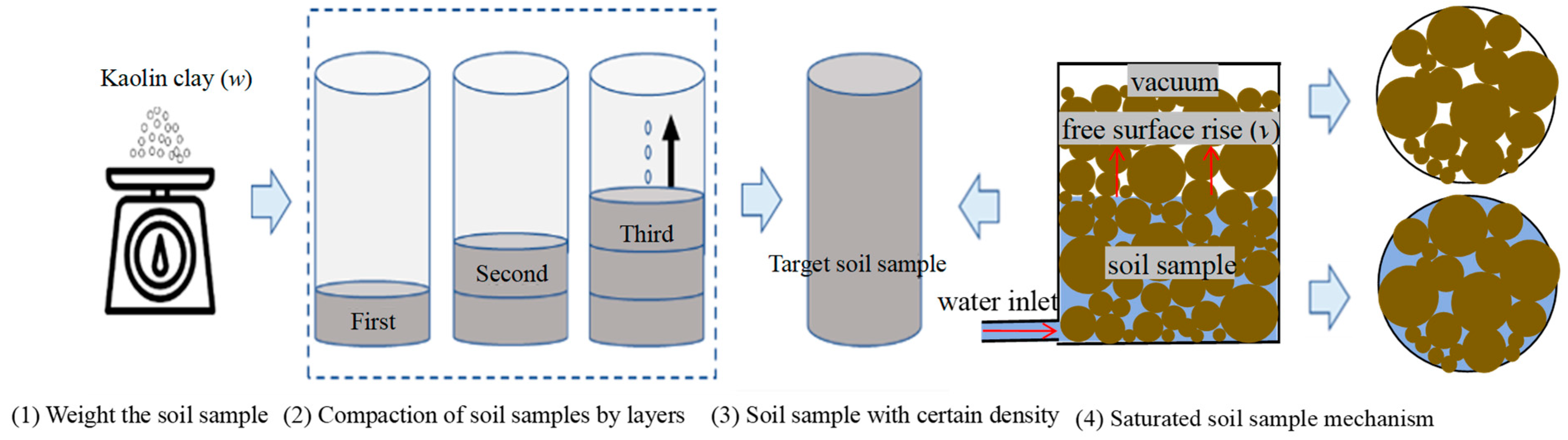
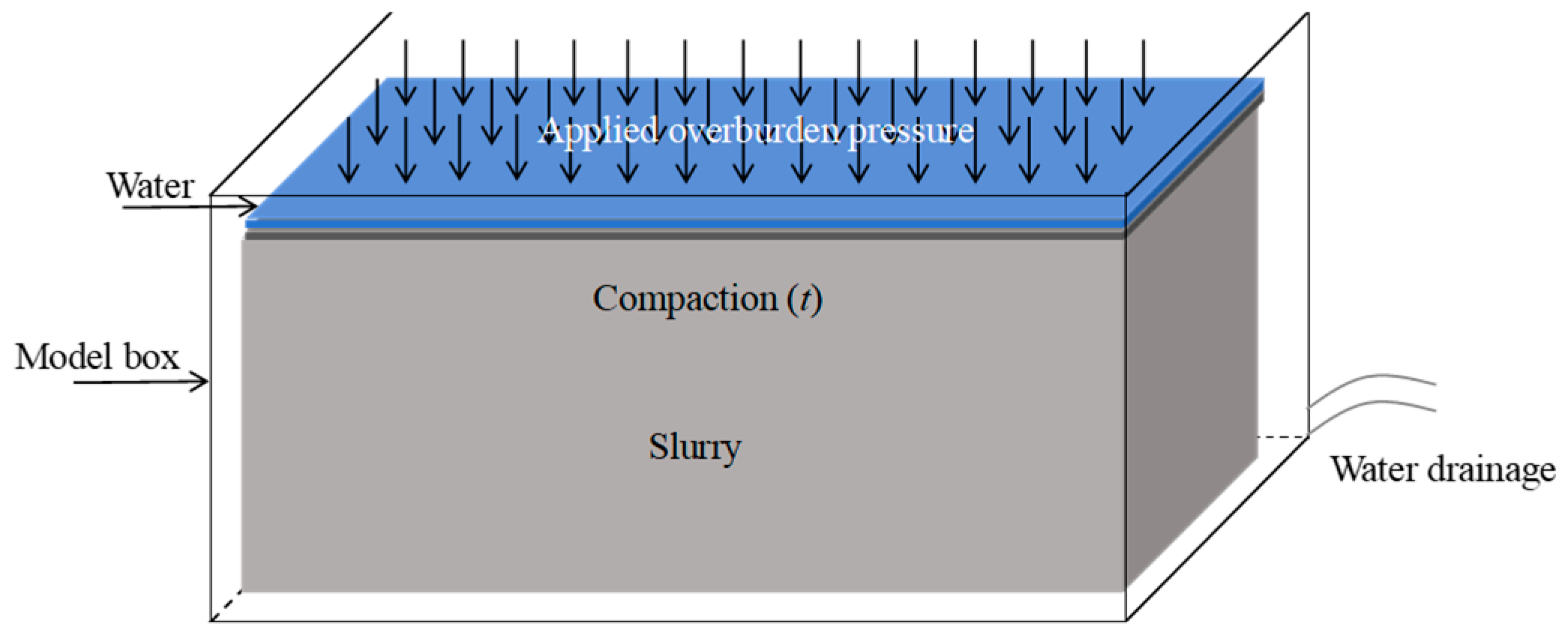
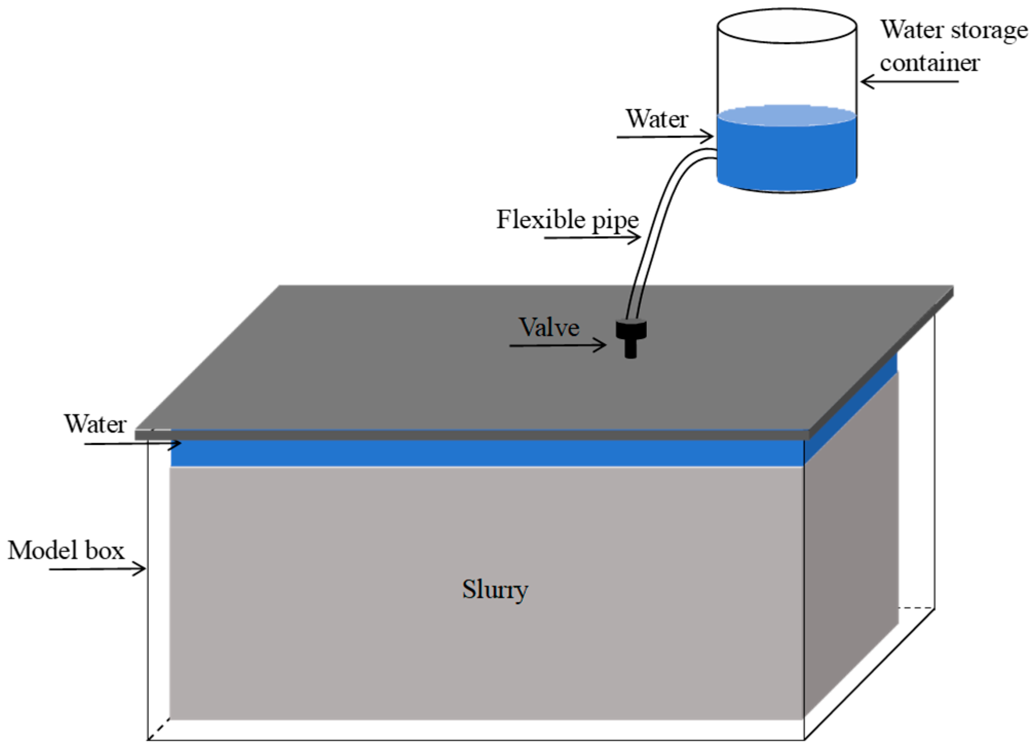
where e0 is the initial void ratio of the soil sample, Gs is the specific gravity of the soil solids, w0 is the initial water content of the soil sample, ρ0 is the initial density of the soil sample, and ρw is the density of water. Figure 1 and Figure 2 provide a comprehensive overview of the current methods used for the consolidation of saturated clay. Figure 3 illustrates the process of preparing soil samples through capillary wetting and vacuum saturation. The preparation of soil samples is primarily influenced by the control of two critical parameters: the initial void ratio and initial water content. These parameters are crucial for determining the initial state of the soil samples and its subsequent behavior during consolidation. Both columnar (Dc × Hc = 100 × 100 mm) and large-volume (Lrec × Wrec × Drec = 300 × 300 × 200 mm) soil samples were prepared using the vacuum–capillary technique, as shown in Figure 3. The initial void ratios of the columnar soil samples were set at e0 = 1.8, 2.1, 2.3, and 2.6, while those of the large-volume soil samples were set at e0 = 2.1, 2.3, and 2.5. The initial water contents were set at w0 = 20% and 10% for the columnar and large-volume soil samples, respectively. These target void ratios were selected to represent the high-void-ratio characteristics of very soft marine clay and the corresponding high water contents after saturation. Both initial water content values were below the plastic limit (PL = 34%) and were selected to facilitate layered compaction and establish the target void ratio before saturation. For saturated soil, the water content corresponding to a given void ratio can be estimated as w = e/Gs. With Gs = 2.61, e0 = 1.8, 2.1, 2.3, and 2.6 correspond to saturated water contents of 69%, 80%, 88%, and 100%, respectively, all exceeding the liquid limit of the kaolin. It should be noted, however, that the samples were not prepared by directly pouring slurry at these high water contents. Instead, the target void ratios were obtained by controlling the dry soil mass and sample volume at the prescribed initial water contents, followed by layered compaction and the vacuum–capillary technique. Thus, even high-void-ratio samples had an initially formed soil skeleton and were different from freely flowing slurry [30]. This preparation procedure is particularly useful for producing high-void-ratio saturated clay samples that are difficult and time-consuming to obtain using conventional slurry-consolidation methods. Through Equation (1), the initial density of the soil samples was calculated, which facilitated the determination of the required soil mass. Subsequently, the soil samples were then compacted in layers using a compaction method to ensure uniformity and achieve the desired density. To prevent stratification and ensure structural integrity between layers, the surface of each compacted layer was scarified to a depth of 2–3 mm before adding the subsequent layer. This procedure promotes particle interlocking between layers, effectively mitigating the density gradients typically associated with the layered compaction method. After compaction, the soil samples were subjected to a saturation period of two days. This dual approach effectively removes air from the soil samples while simultaneously allowing water to infiltrate and saturate them under a controlled negative pressure. Specifically, a sustained vacuum pressure of −80 kPa was applied to the vacuum tank. This significant hydraulic gradient accelerates the extraction of entrapped air from the soil pores, resulting in a more thorough and uniform saturation of the soil samples compared to conventional soaking.
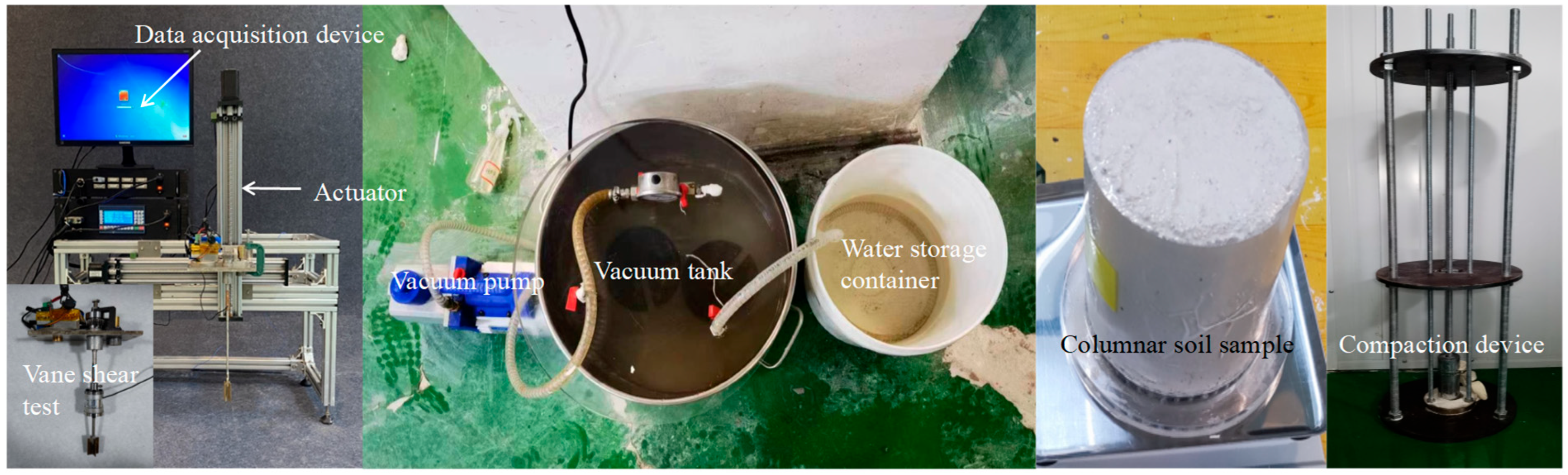
The proposed vacuum–capillary technique differs from traditional methods. Kaolin was initially compacted at a water content below the plastic limit (w0 < PL = 34%) and subsequently saturated by vacuum-assisted capillary wetting under a sustained vacuum pressure of −80 kPa. The prepared soil samples were intended for laboratory model tests requiring saturated kaolin with controlled engineering properties. As shown in Figure 4, the columnar soil sample was treated using the vacuum–capillary technique. The test setup consisted of several key components: a vacuum pump for air extraction, a vacuum tank that served as a chamber to hold the soil samples and water, a water storage container, and a compaction device designed to compact the soil samples. This arrangement ensured that the soil sample was thoroughly saturated without visible cracks. The undrained shear strength of the saturated soil samples was assessed using the vane shear test. The test device incorporated a drive, data acquisition system, and vane loading system to conduct the test. In this experiment, the vane shear test employed a vane with a diameter of 25 mm and a height of 50 mm.
The experimental setup was developed with reference to previous studies on saturation methods [31], capillary wetting [16], and the preparation of large-size cohesive soil deposits [3]. Each experimental condition was represented by a single independently prepared soil sample. Five columnar soil samples were prepared for the saturation comparison, with one sample assigned to each saturation condition. For the vane shear tests, one columnar soil sample was prepared for each target initial void ratio. Three large-volume soil samples were prepared for the T-bar penetration test and the spatial vane shear tests. Measurements at different depths or locations within the same soil sample were used to characterize within-sample spatial uniformity.

2.2. Soil Properties and Initial Conditions

In this study, we used kaolin clay, specifically the Spes-white brand, produced by Imerys Minerals in the United Kingdom. Kaolin is favored for simulating the properties of seabed soft clay, as demonstrated by its application in various studies [32,33,34]. The kaolin clay had a pH value of 5 with liquid and plastic limits of LL = 65% and PL = 34%, respectively. Characterized by its fine-grained particles, kaolin boasts a specific surface area of 11 m2/g, indicating its high reactivity and adsorption capacity. The specific gravity of the soil solids was Gs = 2.61. Additionally, the vertical consolidation coefficient of kaolin was cv = 1.2 m2/year, a critical parameter for understanding the soil’s ability to consolidate under load. For the purposes of this study, the kaolin raw material was initially in a loose state. The kaolin was mixed with water to reach the prescribed initial water content, and the samples were then prepared by layered compaction followed by the vacuum–capillary technique.

3. Results and Discussions

3.1. Saturation Test

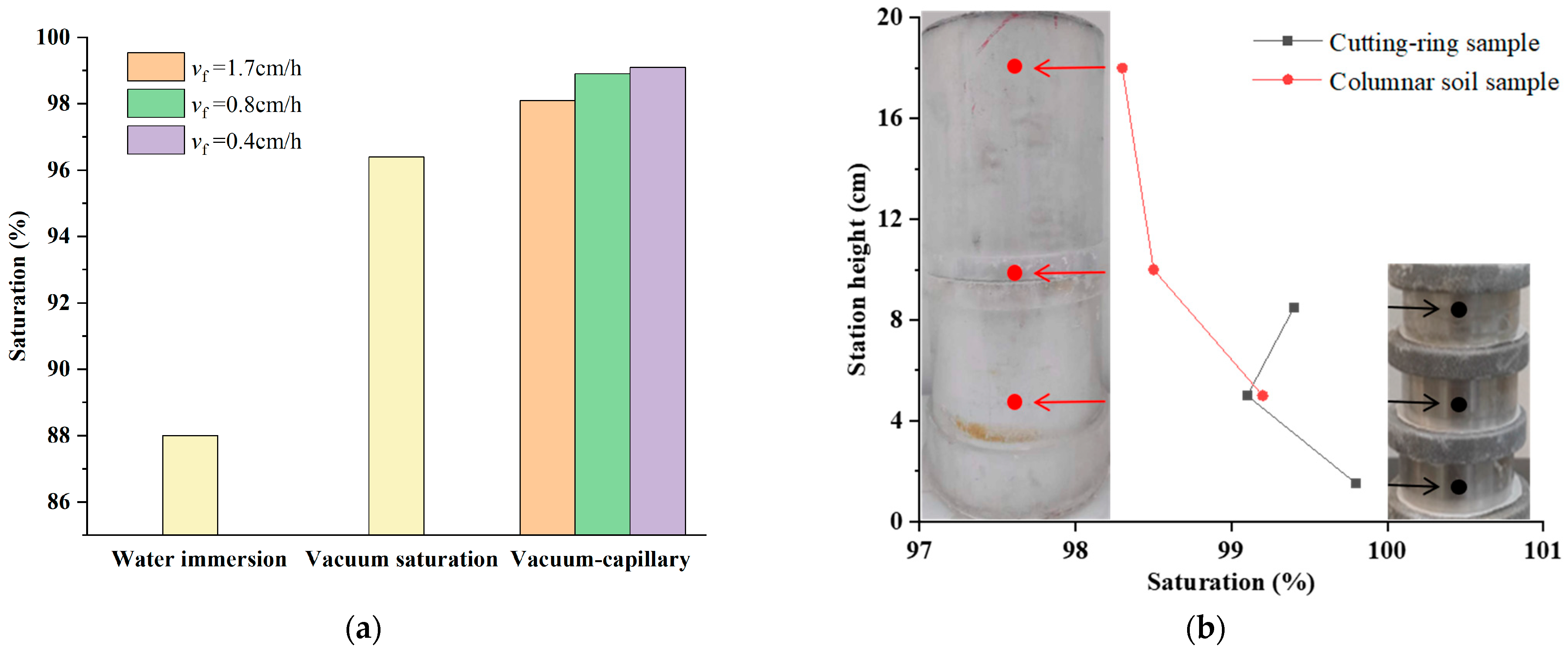
In the context of capillary wetting and vacuum saturation method, the velocity at which the free surface of water rises can significantly influence the saturation level achieved in the soil sample. To investigate this, we prepared five identical soil samples, each with an initial void ratio of e0 = 2.0 and an initial water content of w0 = 20%, and subjected them to different saturation techniques. This test series provided a direct comparison of water immersion, vacuum saturation, and the proposed vacuum–capillary technique under the same initial soil conditions. One sample was immersed in water, while another was saturated using the vacuum saturation method. The remaining three soil samples underwent capillary wetting and vacuum saturation, but with varying free surface rise velocities. Specifically, velocities of vf = 0.4, 0.8, and 1.7 cm/h were employed to assess their effect on the saturation process. The saturation was measured using the gravity method (Figure 5). The soil samples prepared using the vacuum saturation method achieved a saturation of 96.5%, while those soaked in water reached a slightly lower saturation of 88%. Under the same initial void ratio and water content, all samples treated using the vacuum–capillary technique achieved higher saturation than those treated using water immersion or vacuum saturation. Unlike the underwater vacuum preloading method reported by Zhou and Guo [25], which improves marine clay through drainage and consolidation, the proposed vacuum–capillary technique accelerates the saturation of a pre-compacted soil skeleton without relying on consolidation-induced densification. It was observed that an increase in the free-surface rise velocity correlated with a decrease in saturation. This phenomenon can be attributed to the fact that a higher velocity of the free surface rise reduces the time available for capillary penetration, resulting in incomplete displacement of air by water within the soil sample. In this study, we conducted a comparative analysis of the saturation between columnar soil samples of varying heights and cutting-ring soil samples, all tested under identical conditions. Our findings indicated that although the saturation of both the cutting-ring and columnar soil samples exceeded the minimum standard of 95%, the cutting-ring soil samples exhibited significantly higher saturation than the columnar soil samples. This difference in saturation is attributable to variations in the geometry of soil samples. As shown in Figure 5, the saturation at the bottom of the columnar soil sample was significantly higher than at the top. This is due to the longer seepage path inherent in the 20 cm columnar soil sample. Compared to the 8 cm cutting-ring sample, overcoming the hydraulic resistance and effectively displacing the entrapped air within the fine pores over this extended length requires a substantially higher hydraulic gradient. Consequently, the upper portion of the columnar soil sample, being furthest from the wetting front, experienced a less effective saturation process. Consequently, the bottom part of the columnar soil sample, which had a longer exposure time to the saturating water, tended to achieve higher saturation. Nevertheless, the lowest saturation recorded for the columnar soil sample was 97%, which still met the requirements for the preparation of saturated soil samples.

3.2. Vane Shear Test in Columnar Soil Sample

Vane shear tests were conducted to evaluate the effects of the initial void ratio and penetration depth on the strength characteristics of the soil samples. These tests were performed in strict accordance with the guidelines outlined in the ASTM D4648/D4648M-16 [35] standard, ensuring the reliability and consistency of the results. The columnar soil samples, each with distinct initial void ratios of e0 = 1.8, 2.1, 2.3, and 2.6, were subjected to vane shear tests at a controlled rotation rate of 6°/min [36]. The undrained shear strength was calculated using the following equation [37]:
s u = T π D 2 H 2 + π D 3 6
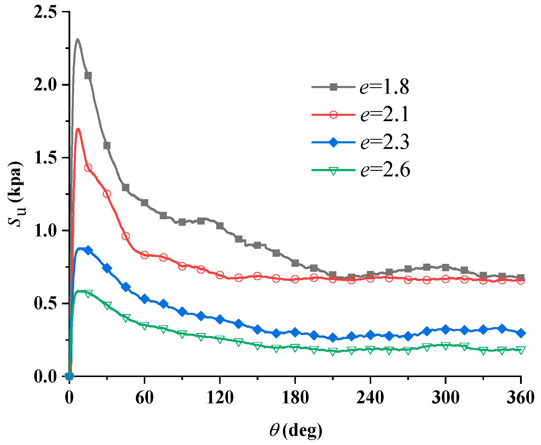
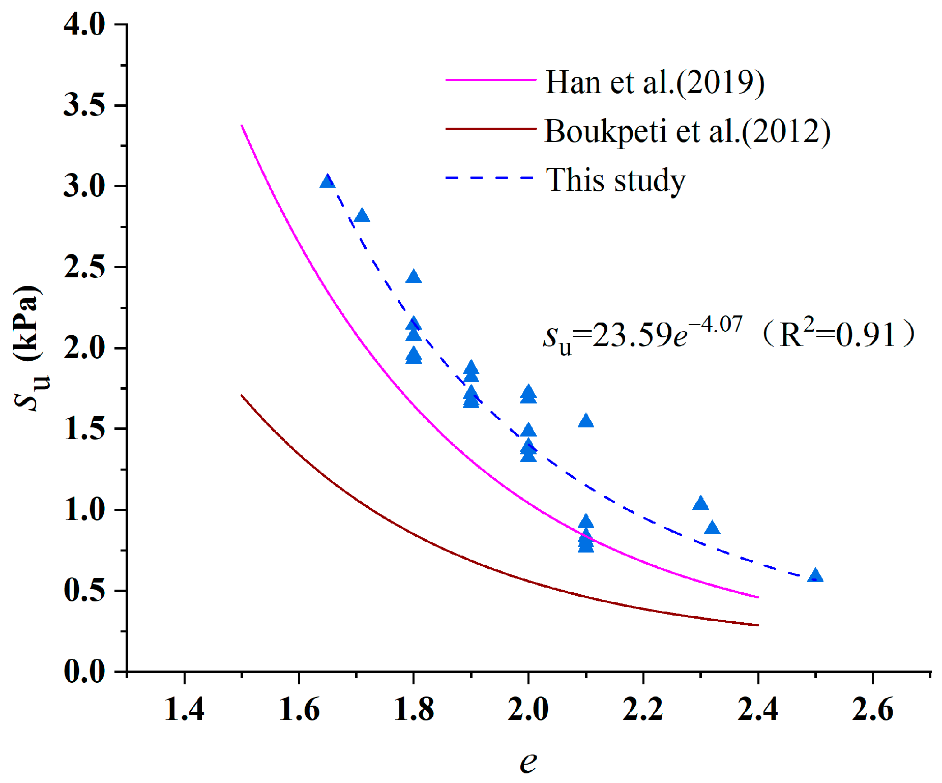
where T is the peak torque measured during vane rotation, D is the diameter of the vane, and H is the height of the vane. Figure 6 illustrates the relationship between the undrained shear strength of the soil samples, each with one of the four distinct initial void ratios, and the rotation angle. A key observation from the test results was that the undrained shear strength of the soil samples reached the maximum when the vane was at an angle of 25°. Beyond this angle, as the vane continued to rotate, the soil sample experienced disturbance and eventually failed. Furthermore, it was observed that an increased initial void ratio corresponded to a reduced undrained shear strength of the soil sample. This relationship is further demonstrated by the leftward shift in the peak strength along the shear strain rate axis, indicating that samples with larger void ratios reach their peak strengths at lower shear strain rates. Figure 7 illustrates the variation in the undrained shear strength of soil samples with different initial void ratios. An inverse relationship was observed between the initial void ratio and the undrained shear strength of the soil samples. Specifically, at an initial void ratio of e0 = 1.8, the soil exhibited an undrained shear strength of su = 2.0 kPa. As the initial void ratio increased to e0 = 2.1, the undrained shear strength decreased to su = 0.8 kPa. In the current study, the targeted undrained shear strength of the prepared soil samples ranged from 0.7 to 3.0 kPa. It is imperative to note that this strength range represents the specific testing conditions rather than a fundamental limitation of the proposed method. Because the mechanical compaction phase is entirely decoupled from the subsequent saturation phase, higher shear strengths—which are routinely required for bearing capacity assessments in offshore engineering—can be readily achieved by applying greater compactive effort to reduce the initial void ratio prior to the vacuum–capillary process.
Based on vane shear and viscometer tests on remoulded kaolin, Boukpeti et al. [38] obtained the following relationship between the undrained shear strength and water content:
s u = 0.205 w 3.86
where su is the undrained shear strength on soil sample and w is the water content of soil sample. The value of w can be estimated in terms of Gs and Sr, by
w = e S r G s
where Sr is saturation of soil sample and e is void ratio of soil sample. For saturated soil, Sr = 1. By adopting Gs = 2.6, as reported by Boukpeti et al. [38], the value of su can be estimated according to
s u = 0.205 ( e 2.6 ) 3.86
Han et al. [39] obtained the relationship between the saturated unit weight and undrained shear strength of saturated kaolin using a T-bar cyclic penetration test, which can be expressed as shown in Equation (6).
γ sat = 10 + 5.03 s u 0.16
where γsat is the saturated unit weight of the soil sample. By combining Equation (6) with the conventional relationship between saturated unit weight and void ratio, Equation (6) can be rewritten as
s u = ( 15.578 0.2 e 5.03 e + 5.03 ) 6.25
The relationship between the undrained shear strength and initial void ratio of soil samples was obtained using vane shear test for soil samples with different initial void ratios, which is similar to Boukpeti et al. [38] and Han et al. [39] (Figure 7):
s u = 23.59 e 4.07
However, the findings of this study indicate slightly higher undrained shear strength values compared to previous research. Boukpeti et al. [38] prepared kaolin soil samples with a water content of 120% using a mixer and subjected them to consolidation under a static pressure machine for five days. They added de-aired water to reshape the samples, a process that disrupted the structural and cementation forces between the original soil particles, leading to a reduction in strength. Similarly, Han et al. [39] prepared kaolin soil samples with a water content of 120% using the hydraulic gradient similarity method and measured the undrained shear strength using T-bar penetration tests. Previous studies using the same commercial kaolin reported substantially longer preparation periods. Slurry samples prepared by staged consolidation in a consolidation box required 28 days, with the consolidation pressure applied in four stages [40]. For normally consolidated Spes-white kaolin prepared using the hydraulic gradient method, the reported consolidation period was approximately three weeks [41]. In comparison, the proposed vacuum–capillary technique enabled large-volume saturated kaolin samples to be prepared within 24–48 h. In contrast, the kaolin soil samples in this study were prepared at initial water contents below the plastic limit and saturated using the vacuum–capillary technique. Unlike conventional slurry consolidation techniques (e.g., w = 120%), which necessitate prolonged drainage periods to dissipate excess pore water pressure and form a stable soil matrix, the lower initial water content adopted in this study facilitates the immediate establishment of a robust soil skeleton via mechanical compaction. In contrast to conventional slurry consolidation, in which the soil skeleton is established through the consolidation process, the soil skeleton in the present method is established by mechanical compaction before saturation. The target void ratio is controlled by the dry soil mass and sample volume during compaction, while the subsequent vacuum–capillary process accelerates saturation without relying on consolidation-induced densification. Therefore, the final undrained shear strength is governed primarily by the target void ratio established before saturation. Additionally, the vane size used in this study was larger than those used in previous studies, which contributed to a more uniform stress distribution across the soil samples. This larger vane size helps mitigate local stress concentrations and reduces the risk of localized failures, thereby measuring higher undrained shear strength values.

3.3. T-Bar Penetration Test

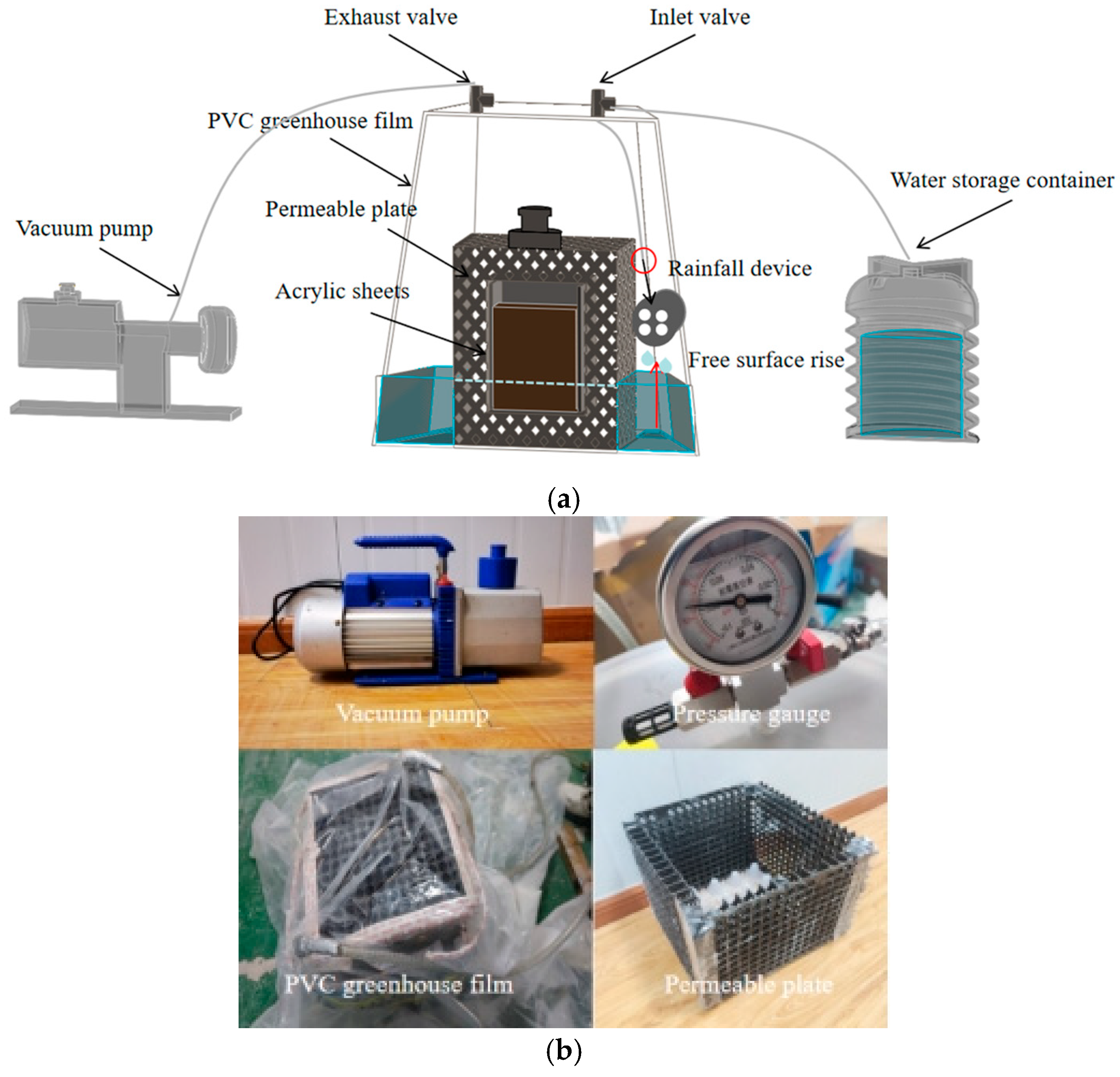
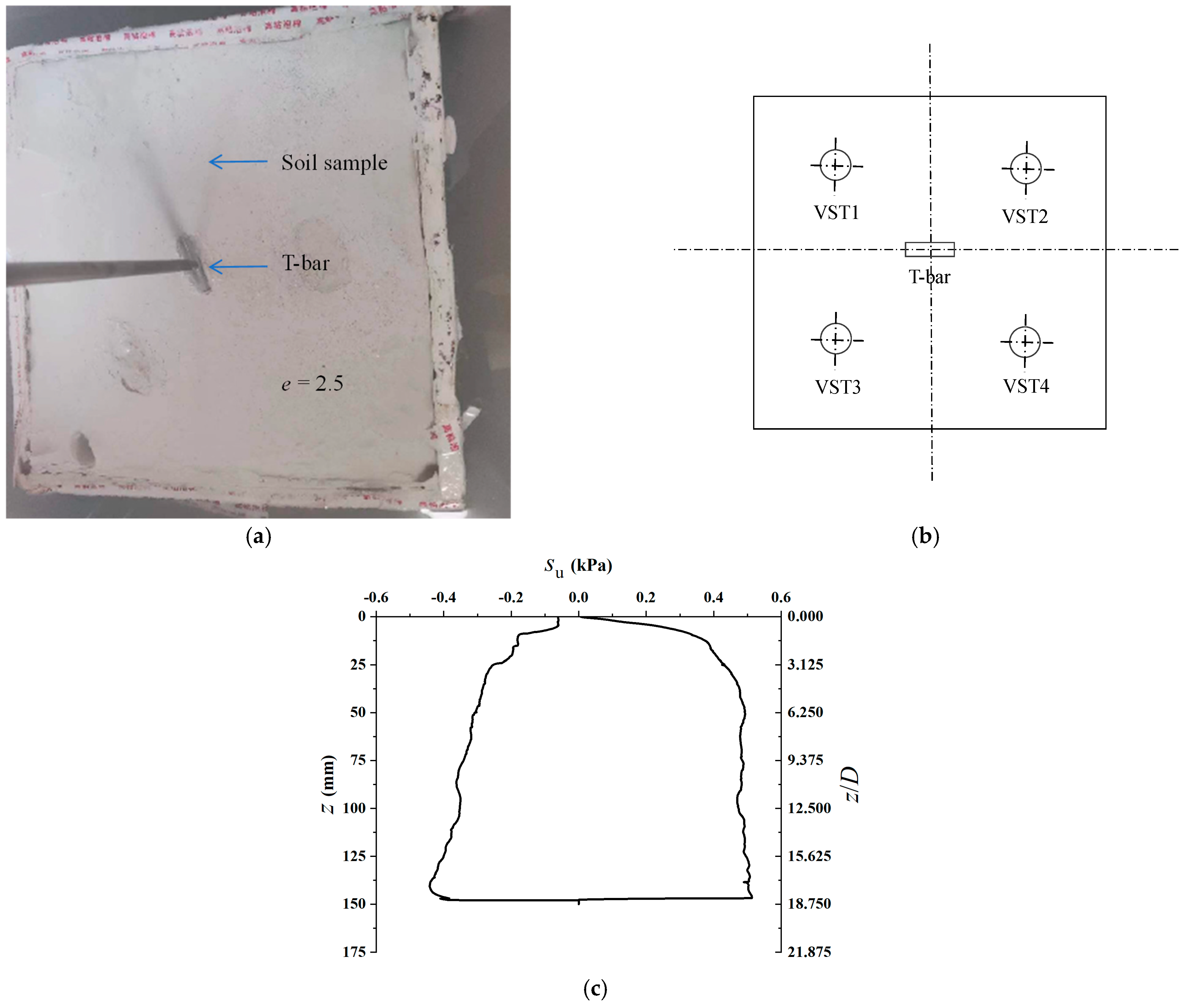
Figure 8 shows the large-volume soil sample saturation device specifically designed for the preparation of large-volume soil samples. A key difference between this device and those used for columnar soil samples is the use of polyvinyl chloride (PVC) greenhouse films to seal the vacuum tank. This sealing is achieved through a dual method, combining heat sealing and adhesive sealing, to ensure an effective and secure closure. The heat-sealing method provides a strong initial seal, while the adhesive is applied to the outer edge to create a complete and airtight barrier, preventing any air leakage that could compromise the saturation process. The PVC film was supported by the permeable plates and acrylic sheets during vacuum application, forming an airtight enclosure around the soil sample. Water entered the large-volume soil sample through the permeable plates installed along the bottom and lateral boundaries. The upper surface of the soil sample remained connected to the vacuum chamber, allowing the displaced air to migrate upward and be continuously extracted during the vacuum–capillary process. The device also features an innovative water injection mode that simulates rainfall. During the injection process, any air entrapped in the falling water droplets is simultaneously removed by the vacuum, saving time that would otherwise be spent preparing de-aired water. However, it is essential that the water pipe is positioned below the top surface of the soil sample to ensure efficient extraction of air within the soil, avoiding any potential obstructions to the saturation process. Figure 9 presents the T-bar test arrangement and measured strength profile for the prepared large-volume soil sample. In this study, a T-bar penetrometer with a diameter of 8 mm and length of 40 mm was used. The T-bar penetration test was conducted on large-volume soil samples with an initial void ratio (e0 = 2.5) and water content (w0 = 10%), which were prepared using the capillary wetting and vacuum saturation method, as shown in Figure 9. The test was performed at a controlled penetration velocity of 1 mm/s. When the dimensionless velocity V > 30.0 (V = vDT-bar/cv), the soil sample is in an undrained state [42,43]. The undrained shear strength was interpreted as su = qT/NT-bar, using a T-bar bearing factor of NT-bar = 10.5 [43,44]. The arrangement of the measurement setup is shown in Figure 9. The vane shear test locations provided a minimum clearance of 62.5 mm (2.5 D) from the sidewalls and a center-to-center spacing of 150 mm (6 D) between adjacent test locations. The T-bar penetration path provided a horizontal clearance of 150 mm (18.75 DT-bar) from the sidewalls and a vertical clearance of 50 mm (6.25 DT-bar) from the model box base at the maximum penetration depth. Figure 9 shows the results of the T-bar penetration test. The interpreted undrained shear strength of the soil sample increased progressively as the penetration depth increased from 0 to 40 mm, with the rate of increase decelerating over this range. Beyond a penetration depth of 40 mm, the undrained shear strength of the soil sample stabilized at approximately 0.48 kPa as the depth further extended to 150 mm. At shallow embedment, the full-flow mechanism around the T-bar was not fully mobilized. Because a constant full-flow T-bar bearing factor of NT-bar = 10.5 was used without a shallow-embedment correction, the interpreted undrained shear strength within the upper 40 mm may be underestimated [44]. Therefore, the upper 40 mm was excluded from the evaluation of sample uniformity. The soil sample, which had a total height of 200 mm, was stratified into layers of 50 mm thickness. At penetration depths of 50 and 100 mm, the undrained shear strength of the soil sample exhibited minimal variation, indicating no significant stratification effects. This consistency in strength suggests a relatively uniform soil composition in these layers. The relatively stable undrained shear strength below a penetration depth of 40 mm demonstrated the spatial uniformity of the middle and lower layers of the large-volume soil sample.

3.4. Vane Shear Test in the Large-Volume Soil Sample

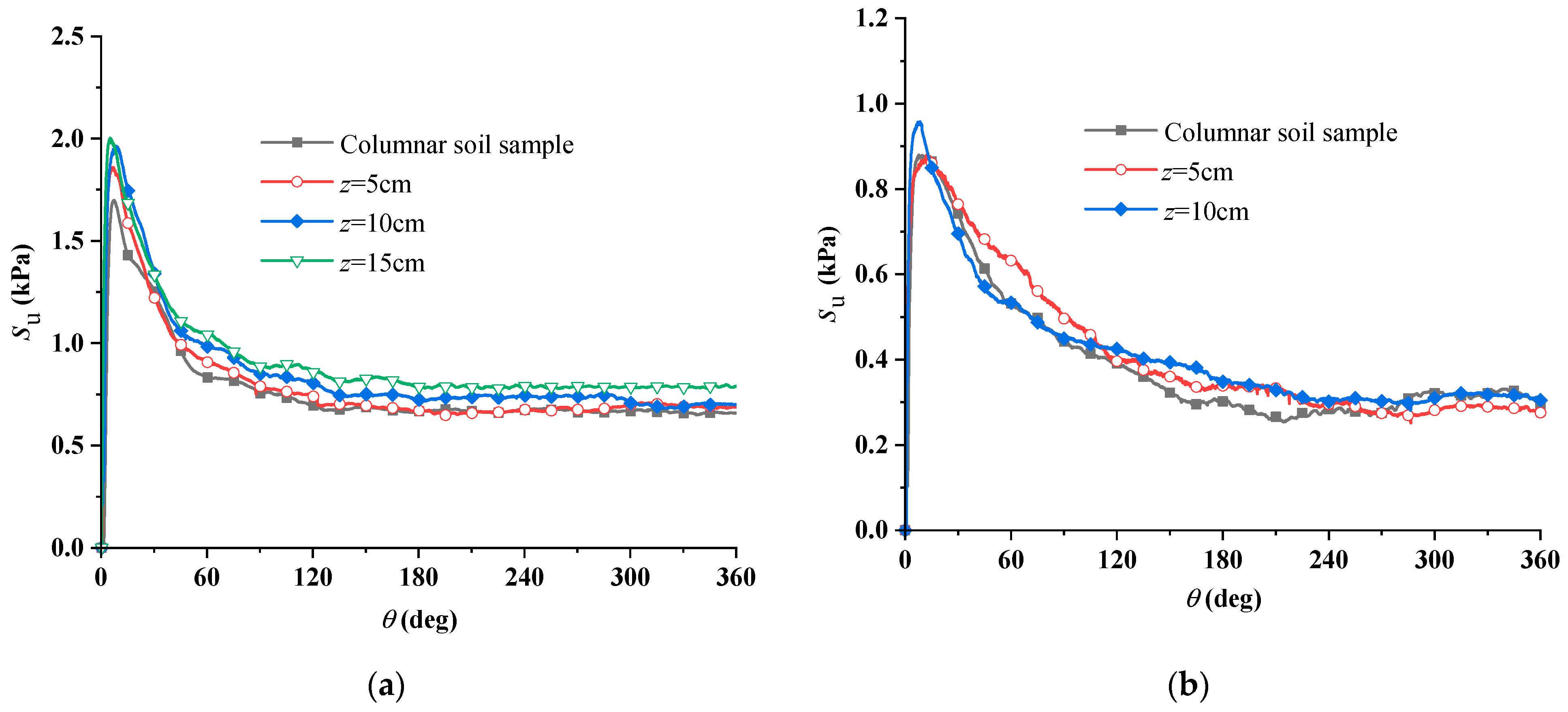
The vane shear test was performed on large-volume soil samples with initial void ratios of e0 = 2.1, 2.3, and an initial water content of w0 = 10%. Figure 10 compares the vane shear responses of the large-volume and columnar soil samples at the corresponding initial void ratios. Although the columnar and large-volume samples were prepared at different initial water contents (w0 = 20% and 10%, respectively), their measured undrained shear strengths were comparable at the same target void ratio. This consistency indicates that, within the investigated range, the final undrained shear strength is governed primarily by the target void ratio established by controlling the dry soil mass and sample volume during compaction, whereas the initial water content below the plastic limit mainly facilitates the formation of the compacted soil skeleton. The relatively lower vane shear strength measured at the shallowest test locations (z = 5 cm) in Figure 10 may indicate some upper-boundary softening possibly associated with the limited overburden pressure during saturation. In contrast, the limited strength variation observed in the middle and lower layers indicates spatial uniformity within these regions. Overall, the measured undrained shear strength profiles were relatively consistent across the tested locations and depths, indicating reasonable spatial uniformity of the prepared large-volume soil samples in the middle and lower layers.

4. Conclusions

This study developed a time-efficient method for preparing high-quality saturated clay samples by combining capillary wetting and vacuum saturation. The method was evaluated using the gravity method, the cutting-ring method, vane shear tests, and T-bar penetration tests and was subsequently applied to the preparation of a large-volume clay sample. The main conclusions are as follows:
(a)
The new capillary wetting and vacuum saturation method produced columnar soil samples with saturation levels of at least 97%. For the large-volume (300 mm × 300 mm × 200 mm) clay samples, the measured strength profiles indicated spatial uniformity in the middle and lower layers. This represents a significant improvement in efficiency, allowing large-scale samples to be prepared within 24–48 h, a substantial reduction compared to traditional time-consuming methods.
(b)
In the present tests, saturated clay samples with undrained shear strengths of 0.7–3.0 kPa were obtained by controlling the target void ratio before saturation. The results demonstrate that the proposed vacuum–capillary technique is suitable for preparing saturated kaolin specimens characterized by high void ratios and low strengths. The vacuum–capillary process primarily serves to accelerate saturation after the compacted soil skeleton has been formed. Consequently, the final undrained shear strength is governed mainly by the target void ratio and the compaction state established prior to saturation, rather than by the saturation process itself. In principle, this method can also be used to prepare clay specimens with higher strengths by employing a lower target void ratio or greater compactive effort before saturation. The free-surface rise velocity and saturation duration may require adjustment when the technique is applied to natural marine clays with different mineralogical compositions, plasticities, and permeabilities.
(c)
Although a slight gradient in saturation was observed (with the top layer being marginally less saturated than the bottom) due to the influence of the free-surface rise velocity during capillary wetting, the overall saturation level remained consistently high, with the minimum value not lower than 97%. Furthermore, the undrained shear strength profile with depth, particularly in the middle and lower layers of the large sample, effectively demonstrated the overall uniformity of the soil mass.
(d)
The results support the feasibility of using this method for the rapid preparation of saturated kaolin samples for marine geotechnical model testing. While the current sample size was limited by the laboratory vacuum apparatus, the principle shows potential for the efficient preparation of large-volume samples, facilitating further laboratory investigations into soil–structure interaction. Further verification using natural marine clays with different properties is required before the method can be applied more broadly.

Author Contributions

Conceptualization, L.Y., X.Z., Y.H., L.C., X.F., G.Y. and Q.Y.; methodology, L.Y., Y.H. and Q.Y.; validation, L.Y., Y.H., G.Y. and Q.Y.; writing—original draft preparation, L.Y. and X.Z.; writing—review and editing, X.Z., L.C., X.F. and Q.Y.; supervision, L.C., X.F., G.Y. and Q.Y.; project administration, L.Y.; funding acquisition, L.Y., Y.H. and Q.Y. All authors have read and agreed to the published version of the manuscript.

Funding

This research was funded by the National Natural Science Foundation of China, grant numbers 52531010, 52571282 and 52171252; the Liaoning Province Doctoral Research Startup Fund Program, grant number 2022BS082; and the Fundamental Research Funds for the Central Universities, grant number DUT23RC(3)018.

Data Availability Statement

All data, models, and code generated or used during the study appear in the published article.

Conflicts of Interest

The authors declare no conflicts of interest. The funders had no role in the design of the study; in the collection, analyses, or interpretation of data; in the writing of the manuscript; or in the decision to publish the results.

Glossary

e0= the initial void ratio of the soil sample
ρw= the density of water
Gs= the specific gravity of the soil sample
w0= the initial water content of the soil sample
ρ0= the initial density of the soil sample
LL= the liquid limit of the soil sample
PL= the plastic limit of the soil sample
cv= the vertical consolidation coefficient of the soil sample
su= the undrained shear strength of the soil sample
qT= the T-bar penetration resistance
NT-bar= the T-bar bearing factor
T= the peak torque measured during vane rotation
D= the diameter of the vane
DT-bar= the diameter of the T-bar
H= the height of the vane
Lrec= the length of the rectangular soil sample
Wrec= the width of the rectangular soil sample
Drec= the depth of the rectangular soil sample
Dc= the diameter of the columnar soil sample
Hc= the height of the columnar soil sample
z= the penetration depth of the vane
v= the penetration velocity of the T-bar
vf= the free-surface rise velocity
Sr= the saturation of the soil sample
e= the void ratio of the soil sample
γsat= the saturated unit weight of the soil sample

References

  1. Han, C.; Liu, D.; Liu, J. Keying process of the OmniMax anchor shallowly embedded in undrained normally consolidated clay. J. Waterw. Port Coast. Ocean Eng. 2018, 144, 88–104. [Google Scholar] [CrossRef] [Scilit]
  2. Liu, J.; Han, C.; Yu, L. Experimental investigation of the keying process of OMNI-Max anchor. Mar. Georesour. Geotechnol. 2019, 37, 349–365. [Google Scholar] [CrossRef] [Scilit]
  3. McManus, K.J.; Kulhawy, F.H. Preparation of large-size laboratory deposits of cohesive soil. Geotech. Test. J. 1993, 16, 372–383. [Google Scholar] [CrossRef] [Scilit]
  4. Randolph, M.F.; House, A.R. The complementary roles of physical and computational modelling. Int. J. Phys. Model. Geotech. 2001, 1, 1–8. [Google Scholar] [CrossRef] [Scilit]
  5. Roy, N.; Sarathi, P. Strain rate behaviour of compacted silt. Int. J. Rock Mech. Min. Sci. Geomech. Abstr. 1976, 102, 347–360. [Google Scholar] [CrossRef] [Scilit]
  6. Tarantino, A.; De Col, E. Compaction behaviour of clay. Geotechnique 2008, 58, 199–213. [Google Scholar] [CrossRef] [Scilit]
  7. Nguyen, V.; Pineda, J.A.; Romero, E.; Sheng, D. Influence of soil microstructure on air permeability in compacted clay. Geotechnique 2021, 71, 373–391. [Google Scholar] [CrossRef] [Scilit]
  8. Fredlund, D.G.; Hasan, J.U. One-dimensional consolidation theory: Unsaturated soils. Can. Geotech. J. 1979, 16, 521–531. [Google Scholar] [CrossRef] [Scilit]
  9. Lloret, A.; Alonso, E.E. Consolidation of unsaturated soils including swelling and collapse behaviour. Geotechnique 1980, 30, 449–477. [Google Scholar] [CrossRef] [Scilit]
  10. Mumtaz, M.B.; Stark, N. Pore pressure dissipation induced by high-velocity impacts of a portable free-fall penetrometer in clays. J. Geotech. Geoenviron. Eng. 2020, 146, 05020008. [Google Scholar] [CrossRef] [Scilit]
  11. Zelikson, A. Geotechnical models using the hydraulic gradient similarity method. Geotechnique 1969, 19, 495–508. [Google Scholar] [CrossRef] [Scilit]
  12. Chow, S.H.; Airey, D.W. Free-falling penetrometers: A laboratory investigation in clay. J. Geotech. Geoenviron. Eng. 2014, 140, 201–214. [Google Scholar] [CrossRef] [Scilit]
  13. Nanda, S.; Sivakumar, V.; Hoyer, P.; Bradshaw, A.; Gavin, K.G.; Gerkus, H.; Jalilvand, S.; Gilbert, R.B.; Doherty, P.; Fanning, J. Effects of strain rates on the undrained shear strength of kaolin. Geotech. Test. J. 2017, 40, 951–962. [Google Scholar] [CrossRef] [Scilit]
  14. Chapuis, R.P.; Baass, K.; Davenne, L. Granular soils in rigid-wall permeameters: Method for determining the degree of saturation. Can. Geotech. J. 1989, 26, 71–79. [Google Scholar] [CrossRef] [Scilit]
  15. Yang, Y.; Liu, J.; Liu, L.; Li, J.; Liu, Q.; Chen, Z.; Shi, C. Quantifying the water saturation degree of cement-based materials by hydrogen nuclear magnetic resonance (1H NMR). Constr. Build. Mater. 2024, 438, 137340. [Google Scholar] [CrossRef] [Scilit]
  16. Hunt, J.E. Suggested method for capillary wetting of soils specimens (compacted and undisturbed). In Special Procedures for Testing Soil and Rock for Engineering Purposes; ASTM International: West Conshohocken, PA, USA, 1970; pp. 192–197. [Google Scholar] [CrossRef] [Scilit]
  17. Luo, S.; Zhou, B.; Likos, W.J.; Lu, N. Determining capillary pore-size distribution of soil from soil-water retention curve. J. Geotech. Geoenviron. Eng. 2024, 150, 04023138. [Google Scholar] [CrossRef] [Scilit]
  18. Lowe, J.; Johnson, T.C. Use of back pressure to increase degree of saturation of triaxial test specimens. In Proceedings of the ASCE Research Conference on Shear Strength of Cohesive Soils, Boulder, CO, USA, 13–17 June 1960; pp. 819–836. [Google Scholar]
  19. Reid, D.; Fanni, R.; Urbina, F.; Fourie, A. Effect of saturation procedures on direct simple shear testing of silt tailings. Geotech. Lett. 2025, 15, 277–282. [Google Scholar] [CrossRef] [Scilit]
  20. Jamil, I.; Ahmad, I.; Ullah, W.; Junaid, M.; Khan, S.A. Uniform large-scale cohesionless soil sample preparation using mobile pluviator. Geomech. Eng. 2022, 28, 521–529. [Google Scholar] [CrossRef]
  21. Guo, J.; Wei, X. The influence of soil saturation on the geotechnical test results. Adv. Civ. Eng. 2022, 2022, 7438757. [Google Scholar] [CrossRef] [Scilit]
  22. Liu, Y.; Qiao, C.S. Research on preparation of jointed rock mass samples in site. Appl. Mech. Mater. 2011, 90–93, 593–596. [Google Scholar] [CrossRef] [Scilit]
  23. Yang, B.; Pan, C.; Lai, J.; Wei, C. Effects of sample preparation methods on the properties of a cohesive soil. In Proceedings of the 4th Geo-China International Conference on Sustainable Civil Infrastructures: Innovative Technologies for Severe Weathers and Climate Changes, Jinan, China, 25–27 July 2016; pp. 191–196. [Google Scholar]
  24. Kazemi, M.; Bolouri, J.B. A curtain traveling pluviator to reconstitute large-scale sand specimens. Geomech. Eng. 2018, 14, 131–139. [Google Scholar] [CrossRef]
  25. Zhou, Y.; Guo, W. Experimental study on a new underwater vacuum preloading method. Bull. Eng. Geol. Environ. 2025, 84, 359. [Google Scholar] [CrossRef] [Scilit]
  26. Hossain, M.S.; Cassidy, M.J.; Hu, Y. T-bar to spudcan design approach in single-layer clays and calcareous silts. J. Geotech. Geoenviron. Eng. 2016, 142, 04016025. [Google Scholar] [CrossRef] [Scilit]
  27. Chen, Y.; Lv, Y.; Wu, K.; Huang, X. Centrifuge shaking table study on the hydrodynamic effects on a pile foundation bridge pier in soft soil under earthquakes. Mar. Struct. 2022, 85, 103261. [Google Scholar] [CrossRef] [Scilit]
  28. Wang, Y.; Hu, Y.; Hossain, M.S. Soil flow mechanisms of full-flow penetrometers in layered clays through particle image velocimetry analysis in centrifuge test. Can. Geotech. J. 2020, 57, 1719–1732. [Google Scholar] [CrossRef] [Scilit]
  29. GB/T 50123-2019; Standard for Geotechnical Testing Method. China Planning Press: Beijing, China, 2019.
  30. Zhao, Y.; Mahmood, N.; Coffman, R.A. Soil fabric and anisotropy as observed using bender elements during consolidation. Int. J. Geomech. 2020, 20, 04020029. [Google Scholar] [CrossRef] [Scilit]
  31. Bouin, C.; Weber, S.; Ethier, Y.A.; Dube, J.-S.; Duhaime, F. On preferred saturation methods for geotechnical flow tests. Geotech. Test. J. 2021, 44, 1135–1152. [Google Scholar] [CrossRef] [Scilit]
  32. Ren, Y.; Guo, W.; Wang, Y.; Yan, S. Theoretical analysis of hall anchor dragged in clay. Ocean Eng. 2022, 265, 112584. [Google Scholar] [CrossRef] [Scilit]
  33. Kou, H.; Hou, W.; Chen, Q.; Zhou, N.; Zhang, M. Responses of model monopile to cyclic lateral loadings in clay. Ocean Eng. 2022, 258, 111743. [Google Scholar] [CrossRef] [Scilit]
  34. Sorlie, E.R.; Hartnik, L.O.; Tran, Q.A.; Eiksund, G.R.; Thakur, V.; Kjennbakken, H.; Degago, S. Physical model tests of clay-rich submarine landslides and resulting impact forces on offshore foundations. Ocean Eng. 2023, 273, 113966. [Google Scholar] [CrossRef] [Scilit]
  35. ASTM D4648/D4648M-16; Standard Test Methods for Laboratory Miniature Vane Shear Test for Saturated Fine-Grained Clayey Soil. ASTM International: West Conshohocken, PA, USA, 2016.
  36. Seng, S.; Tanaka, H. Properties of very soft clays: A study of thixotropic hardening and behavior under low consolidation pressure. Soils Found. 2012, 52, 335–345. [Google Scholar] [CrossRef] [Scilit]
  37. Powrie, W. Soil Mechanics: Concepts and Applications, 2nd ed.; CRC Press: Boca Raton, FL, USA, 2004. [Google Scholar] [CrossRef] [Scilit]
  38. Boukpeti, N.; White, D.J.; Randolph, M.F.; Low, H.E. Strength of fine-grained soils at the solid-fluid transition. Geotechnique 2012, 62, 213–226. [Google Scholar] [CrossRef] [Scilit]
  39. Han, C.; Liu, J.; Zhang, Y.; Zhao, W. An innovative booster for dynamic installation of OMNI-Max anchors in clay: Physical modelling. Ocean Eng. 2019, 171, 345–360. [Google Scholar] [CrossRef] [Scilit]
  40. Han, Y.; Yu, L.; Wang, Z.; Yang, Q.; Hu, Y. A novel T-bar test method ensuring full-flow mechanism in stiffer clay. Geotechnique 2024, 74, 1460–1474. [Google Scholar] [CrossRef] [Scilit]
  41. Han, C.; Zhang, X.; Yi, P.; Liu, J. Experimental investigation on the effect of skirt chamfer on the soil plug heave inside the bucket foundation. In Proceedings of the 5th International Symposium on Frontiers in Offshore Geotechnics (ISFOG 2025), Nantes, France, 9–13 June 2025; pp. 2041–2046. [Google Scholar] [CrossRef]
  42. Lehane, B.M.; O’Loughlin, C.D.; Gaudin, C.; Randolph, M.F. Rate effects on penetrometer resistance in kaolin. Geotechnique 2009, 59, 41–52. [Google Scholar] [CrossRef] [Scilit]
  43. O’Loughlin, C.D.; Zhou, Z.; Stanier, S.A.; White, D.J. Load-controlled cyclic T-bar tests: A new method to assess the combined effects of cyclic loading and consolidation. Geotech. Lett. 2020, 10, 7–15. [Google Scholar] [CrossRef] [Scilit]
  44. White, D.J.; Gaudin, C.; Boylan, N.; Zhou, H. Interpretation of T-bar penetrometer tests at shallow embedment and in very soft soils. Can. Geotech. J. 2010, 47, 218–229. [Google Scholar] [CrossRef] [Scilit]
Figure 1. One-dimensional consolidation method.
Jmse 14 01543 g001
Figure 2. Hydraulic gradient similarity method.
Jmse 14 01543 g002
Figure 3. Principle diagram of capillary wetting and vacuum saturation method.
Jmse 14 01543 g003
Figure 4. Device for preparing columnar soil sample.
Jmse 14 01543 g004
Figure 5. Saturation comparison: (a) influence of free surface rise velocity on saturation (yellow parts denote conventional saturation methods used for comparison); (b) saturation at different depths inside soil sample.
Jmse 14 01543 g005
Figure 6. Relationship between su and the rotation angle (θ).
Jmse 14 01543 g006
Figure 7. Relationship between void ratio and undrained shear strength for Kaolin clay [38,39].
Jmse 14 01543 g007
Figure 8. The devices of soil preparation for large-volume saturated clay: (a) schematic diagram of the test apparatus; (b) photograph of the main test apparatus.
Jmse 14 01543 g008
Figure 9. Test for undrained strength of soil sample: (a) prepared soil sample; (b) the layout of test cases in the model box; (c) measured soil strength profile from the T-bar test.
Jmse 14 01543 g009
Figure 10. Comparison of measured vane test results between the columnar soil sample and the large-volume soil sample for (a) e = 2.1; (b) e = 2.3.
Jmse 14 01543 g010
Disclaimer/Publisher’s Note: The statements, opinions and data contained in all publications are solely those of the individual author(s) and contributor(s) and not of MDPI and/or the editor(s). MDPI and/or the editor(s) disclaim responsibility for any injury to people or property resulting from any ideas, methods, instructions or products referred to in the content.