Article

Sensitivity Analysis of Injection Duration on Combustion Characteristics and Exhaust Emissions in a Marine Diesel Engine


by
Mina Tadros
1,2,* and
Evangelos Boulougouris
1
1
Department of Naval Architecture, Ocean and Marine Engineering, Maritime Safety Research Centre (MSRC), University of Strathclyde, Glasgow G4 0LZ, UK
2
Department of Naval Architecture and Marine Engineering, Faculty of Engineering, Alexandria University, Alexandria 21544, Egypt
*
Author to whom correspondence should be addressed.
J. Mar. Sci. Eng. 2026, 14(10), 883; https://doi.org/10.3390/jmse14100883
Submission received: 23 April 2026 / Revised: 1 May 2026 / Accepted: 8 May 2026 / Published: 10 May 2026

Abstract

This study investigates the role of injection duration in marine diesel engine combustion within an optimised operating framework. While injection parameters are typically analysed in isolation, their interaction within a coupled engine system remains insufficiently understood, particularly under realistic operating conditions. To address this gap, a structured methodology integrating one-dimensional (1D) engine simulation and optimisation is applied to evaluate the sensitivity of injection duration around optimised operating points across multiple engine loads. The approach is based on a calibrated engine model developed in WAVE, coupled with an optimisation framework to determine load-dependent optimal control parameters. Injection duration is then systematically varied around its optimised values to assess its influence on engine performance, emissions, and heat release rate (HRR). This enables the evaluation of the robustness of the optimised solution under realistic deviations. The results demonstrate that injection duration governs the transition between premixed and diffusion-controlled combustion, directly influencing heat release structure, combustion stability, and emissions formation. Longer injection durations promote mixing-limited combustion, leading to reduced peak temperatures and lower nitrogen oxide (NOx) emissions, but increased incomplete combustion products, including carbon monoxide (CO) and unburned hydrocarbons (HCs), due to reduced oxidation efficiency. These effects are strongly load-dependent, with part-load operation showing higher sensitivity. The study provides a system-level interpretation of injection duration as a control variable rather than an isolated parameter, offering new insight into its role in combustion regime transitions and engine response. The proposed framework enables a more physically consistent understanding of injection control in modern electronically controlled marine diesel engines and supports the development of robust optimisation and calibration strategies.

1. Introduction

Marine diesel engines operate over a wide range of loads and speeds, where performance and emissions are governed by strongly nonlinear thermodynamic and combustion processes. While slow-speed marine engines typically operate under quasi-steady conditions that can promote favourable mixture preparation and efficient combustion, high-speed and medium-speed engines—particularly under part-load or transient conditions—experience more complex combustion dynamics. Under these conditions, variations in air–fuel mixing, combustion kinetics, and heat release processes can significantly influence engine efficiency, stability, and emissions formation [1,2,3]. At high loads, engines operate close to their design limits, characterised by elevated in-cylinder pressures, high temperatures, and efficient combustion. In contrast, part-load operation introduces challenges such as reduced air–fuel mixing intensity, longer combustion duration, and altered ignition characteristics [4,5,6]. These variations significantly affect engine efficiency, stability, and emissions formation, making load-dependent optimisation essential for modern marine propulsion systems [7,8].
In addition to conventional combustion optimisation, increasing attention has been directed toward the decarbonisation of marine propulsion through the adoption of alternative fuels and advanced propulsion concepts [9,10,11]. Fuels such as biodiesel [12], methanol [13] and hydrogen [14] have been widely investigated as viable pathways to reduce lifecycle emissions and improve fuel flexibility [15,16,17]. In this context, recent studies on diesel–biodiesel operation have demonstrated that fuel properties can significantly influence thermal efficiency, combustion phasing, and emissions behaviour, highlighting the need for adaptive calibration strategies under varying fuel characteristics [18,19]. Furthermore, hybrid propulsion systems and advanced energy-management approaches enable engines to operate closer to optimal efficiency regions, thereby reducing fuel consumption and emissions [20,21,22,23]. Collectively, these developments underscore the importance of flexible, robust engine calibration methodologies that maintain stable combustion and emissions compliance across a wide range of fuels, loads, and operating conditions [24,25].
Recent modelling and optimisation studies recognise that injection parameters must be dynamically adapted across the load diagram to maintain stable combustion and meet emissions constraints; however, the specific role of injection duration within these optimised and coupled control strategies remains unclear [26,27,28]. In this context, the fuel injection system plays a central role, serving as the primary interface between fuel delivery and combustion. Key injection parameters—including fuel rate, start of injection (SOI), injection pressure, and injection duration—directly govern spray formation, atomisation, and the temporal evolution of heat release inside the cylinder [29,30,31]. These parameters strongly influence the position of peak pressure relative to top dead centre (TDC), thereby affecting thermal efficiency and mechanical loading.

2. Literature Review

Injection duration has long been recognised as a key parameter in diesel engine combustion, as it governs the temporal evolution of fuel delivery and consequently affects spray development, mixture formation, and heat-release behaviour. Early investigations into diesel combustion scaling have already highlighted its importance. For instance, Tess et al. [32] demonstrated that injection duration is one of the most sensitive parameters influencing combustion and emissions, indicating that it plays a fundamental role in diffusion-controlled combustion rather than acting as a secondary tuning variable.
With the transition to high-pressure common-rail systems, the interpretation of injection duration evolved significantly. Xu et al. [33] showed that the actual injection duration differs from the electrical energising signal due to injector dynamics, including opening and closing delays. This work highlighted that injection duration should be interpreted through the resulting rate-of-injection (ROI) profile rather than as a purely commanded parameter. Similarly, Salvador et al. [34] demonstrated that injection duration is strongly influenced by injector geometry and hydraulic behaviour, reinforcing its role as part of a coupled injection system.
A parallel line of research has focused on the relationship between injection duration and spray development. Park et al. [35] showed that injection duration is affected by fuel properties and injection conditions, which in turn influence spray penetration, atomisation, and mixture formation—an aspect particularly relevant for marine applications. Similarly, Agarwal et al. [36] reported that higher injection pressures tend to reduce injection duration while improving atomisation, highlighting the strong coupling between injection duration and other injection parameters.
Increasing attention was given to injection-rate shaping and its influence on combustion. Abdullah et al. [37] demonstrated that modifying the injection-rate profile inherently alters effective injection duration and significantly affects spray flame structure and combustion duration. Longer injection durations were associated with extended late combustion, whereas shorter, more intense injections enhanced premixed combustion. Similarly, Nada et al. [38] showed that modifying the temporal structure of injection can reduce late combustion duration and improve soot oxidation by enhancing air entrainment.
Direct investigations of injection duration as an independent variable have also provided valuable insights. Bayramoğlu and Nuran [39] demonstrated that injection duration significantly affects engine performance, combustion temperature, and emissions. Shorter injection durations increase injection rate and spray velocity, promoting better atomisation and mixing, while longer durations distribute fuel over a wider crank-angle interval, resulting in more gradual combustion. However, the study also emphasised that injection duration cannot be optimised independently, as its effects are strongly dependent on injection timing and operating conditions.
In addition to experimental studies, modelling and injector-focused research have further clarified the role of injection duration. Cavicchi et al. [40] showed that injector dynamics and closely spaced injections can significantly modify effective injection duration and ROI profiles. Similarly, Williams et al. [41] highlighted that injection duration, together with injection pressure and nozzle geometry, is a key parameter for accurately predicting spray behaviour in advanced computational fluid dynamics (CFD) simulations.
More recent research has extended the analysis of injection duration to low-carbon and alternative fuels. LeBlanc et al. [42] demonstrated that injection duration determines whether the injection event reaches a steady-state ROI phase. For short durations, injection is dominated by transient injector dynamics, whereas for longer durations, steady-state flow conditions develop, leading to significant differences in spray structure and combustion behaviour. Similarly, dual-fuel studies such as [43] show that injection characteristics, including duration, strongly influence ignition delay, heat-release rate, and emissions formation, although injection duration is often not treated as the primary control variable.
Alongside these developments, the literature has increasingly shifted toward multi-parameter optimisation approaches. Modern studies recognise that injection duration must be considered together with other control variables, including SOI, fuel quantity, and air-management parameters. For example, optimisation frameworks such as [44] demonstrate that injection duration varies systematically with engine load and operating conditions to achieve optimal trade-offs between efficiency and emissions. These findings confirm that injection duration is not an independent tuning parameter but part of an integrated control strategy.
Despite advances in multi-parameter optimisation, most studies focus primarily on parameter tuning rather than on how these parameters interact within the overall engine system. This highlights the need for model-based systems engineering (MBSE) that not only optimises individual variables but also accounts for their combined influence on engine behaviour across different operating conditions.

3. Research Gap and Novelty

Despite extensive research on diesel engine injection systems, the role of injection duration remains insufficiently understood within optimised operating frameworks. Most existing studies analyse injection duration either as an isolated parameter or under fixed operating conditions, focusing on its effects on spray development, combustion, and emissions. However, such approaches do not reflect realistic engine operation, where injection parameters are simultaneously optimised and strongly coupled with other control variables, including SOI, fuel rate, and air management.
Consequently, injection duration is often treated as a tuning parameter rather than as a control variable within a coupled nonlinear engine system. This limits the understanding of how it interacts with overall engine behaviour, particularly under load-dependent and optimised conditions. Moreover, there is a lack of studies that assess the sensitivity of injection duration around an optimised solution. In practical operation, optimal settings are rarely maintained due to control limitations, transient conditions, and environmental variations, yet the impact of such deviations on performance, combustion, and emissions has not been systematically quantified.
This reveals a fundamental scientific gap: the lack of a system-level understanding of how variations in injection duration propagate through coupled thermodynamic, fluid-dynamic, and chemical processes, thereby influencing combustion stability, efficiency, and emissions. This issue is particularly relevant for marine engines, which operate over wide load ranges and under variable conditions.
To address this gap, the present study builds on a previously developed optimisation framework [44], in which the injection duration is determined as part of a multi-parameter optimisation across different engine loads. Rather than re-optimising the system, the focus here is on evaluating the robustness of the optimised solution. Injection duration is systematically varied around its optimal values to quantify its influence on engine performance, emissions, and combustion behaviour under realistic deviations from ideal operation.
The novelty of this work lies in treating injection duration as a system-level control variable and linking its variations directly to changes in combustion regime, heat release characteristics, and overall engine response. This enables a physically grounded interpretation of sensitivity behaviour, moving beyond conventional parametric studies.
Accordingly, the key scientific problem addressed is to quantify and interpret the sensitivity of combustion and emissions to variations in injection duration around optimised operating conditions. The main contributions of this study are:
  • System-level evaluation of injection duration within an optimised multi-parameter framework;
  • Sensitivity analysis around realistic operating conditions rather than isolated parameter variation;
  • Identification of load-dependent behaviour, particularly the increased sensitivity at part load;
  • Establishment of a direct link between injection duration, combustion regime transition, and mixing-limited combustion;
  • Physical interpretation of performance and emissions trends through heat release analysis.
Overall, the proposed approach provides a more realistic and physically consistent understanding of injection duration in modern electronically controlled marine engines.

4. Engine Specifications

The engine investigated in this work is the MAN D2862 LE448 [45], a high-speed, high-performance unit developed for marine propulsion applications. It is derived from the conventional diesel model MAN D2862 LE428 and has been reconfigured to operate in a dual-fuel configuration. The engine can operate in two modes: a liquid mode powered by marine diesel oil (MDO) and a gas mode, in which hydrogen is the primary fuel with pilot ignition.
To support flexible, precise combustion control, the engine is equipped with a common-rail injection system that enables accurate control of injection timing and pressure. Air handling is enhanced by a twin-turbocharger system with a wastegate, ensuring efficient charge-air delivery and improved overall engine performance. The engine is particularly suitable for fast marine vessels such as workboats and small tugboats.
The operating conditions assume ambient intake, with an inlet pressure of 100 kPa and a temperature of 318 K. Under rated conditions, the engine delivers a maximum output of 749 kW at 2100 rpm with brake-specific fuel consumption (BSFC) equal to 208 g/kWh. Its dual-fuel capability reduces greenhouse gas emissions while maintaining high performance and operational versatility, making it a practical solution for modern marine applications. The principal engine specifications are summarised in Table 1. The corresponding operating conditions and key control parameters considered in the simulations are summarised in Table 2.

5. Overview of the Modelling Framework

The marine diesel engine model developed in WAVE [46] is constructed using a systematic, physically based framework that represents the complex interactions among thermodynamics, fluid flow, and mechanical motion that govern engine operation. The aim of this modelling approach is to replicate actual engine performance across a broad spectrum of operating conditions, enabling accurate evaluation of key outputs, such as efficiency, combustion behaviour, and emissions formation, within the context of the optimisation and sensitivity analysis carried out in this study [47]. From a broader modelling perspective, this approach represents the physical behaviour of the engine, linking thermodynamic responses to overall operating conditions and control inputs.
The overall methodological framework adopted in this study consists of two main stages. In the first stage, a previously developed optimisation model [44] is used to determine the optimal combination of key engine control parameters across different operating conditions. In the second stage, the calibrated WAVE model is used to perform a systematic sensitivity analysis, varying injection duration around its optimised values to evaluate its impact on engine performance, emissions, and combustion behaviour. This integrated approach enables both the identification of optimal operating conditions and their robustness assessment under realistic deviations. In this context, the term “framework” refers to a structured methodological workflow that integrates modelling, optimisation, and sensitivity analysis, rather than a standalone computational tool.

5.1. Engine Model Description

To accomplish this, the model incorporates comprehensive descriptions of the engine’s physical configuration, including its geometry, intake and exhaust flow processes, combustion mechanisms, and fuel injection characteristics. These elements are combined within a modular one-dimensional simulation environment, which provides an effective compromise between model accuracy and computational cost. This structure enables efficient execution of repeated simulations required for optimisation procedures and parametric studies over a wide range of engine operating points [4]. Such modularity is consistent with structured system modelling approaches, where individual subsystems are represented independently while maintaining their functional interactions.
The model replicates the configuration of a 12-cylinder, V-type, turbocharged high-speed marine engine. Each cylinder is represented as a thermodynamic control volume, connected to intake and exhaust manifolds through flow elements that emulate valve behaviour using pressure–flow relationships derived from valve lift profiles. This filling-and-emptying approach enables accurate modelling of mass flow, pressure dynamics, and the residual gas fraction within each cylinder.
The intake system consists of a plenum connected to individual runners supplying each cylinder, with pressure losses accounted for through calibrated flow coefficients. On the exhaust side, an exhaust manifold and plenum are used to model the transport of exhaust gases toward the turbine inlet. The intake and exhaust systems are coupled to two parallel turbochargers, each comprising a compressor, a turbine, and a shaft subsystem [48].
Compressor and turbine performance are defined using scaled maps from the WAVE library, calibrated to match the required air mass flow, pressure ratio, and turbocharger speed under rated conditions. A charge-air cooler downstream of the compressor reduces intake temperature, increasing charge density and improving volumetric efficiency. A wastegate is incorporated as a controllable flow restriction to regulate boost pressure and prevent excessive manifold pressure under high-load operation. Additionally, a dimensionless shaft balance parameter is introduced to enforce power balance between the turbine and compressor, thereby improving numerical stability during iterative simulations and optimisation.
Crankshaft kinematics, firing order, and valve timing are defined according to manufacturer specifications, ensuring a realistic representation of cycle-to-cycle interactions and valve overlap effects. Ambient boundary conditions are set to 100 kPa and 318 K at the intake boundary.

5.2. Injection System Modelling

The fuel injection system is modelled to reflect the behaviour of a common-rail injection system, with injection events defined by key parameters including amount of fuel rate, SOI, injection pressure, and injection duration. In the present model, the injection process is represented by a prescribed injection rate profile that governs the temporal evolution of fuel delivery into the cylinder [49]. The fuel is assumed to be marine diesel oil with standard properties, including high cetane number and typical lower heating value, consistent with conventional marine engine operation.
Within a broader system modelling context, these injection parameters can be viewed as control variables that propagate through the combustion process and influence overall engine performance and emissions behaviour.
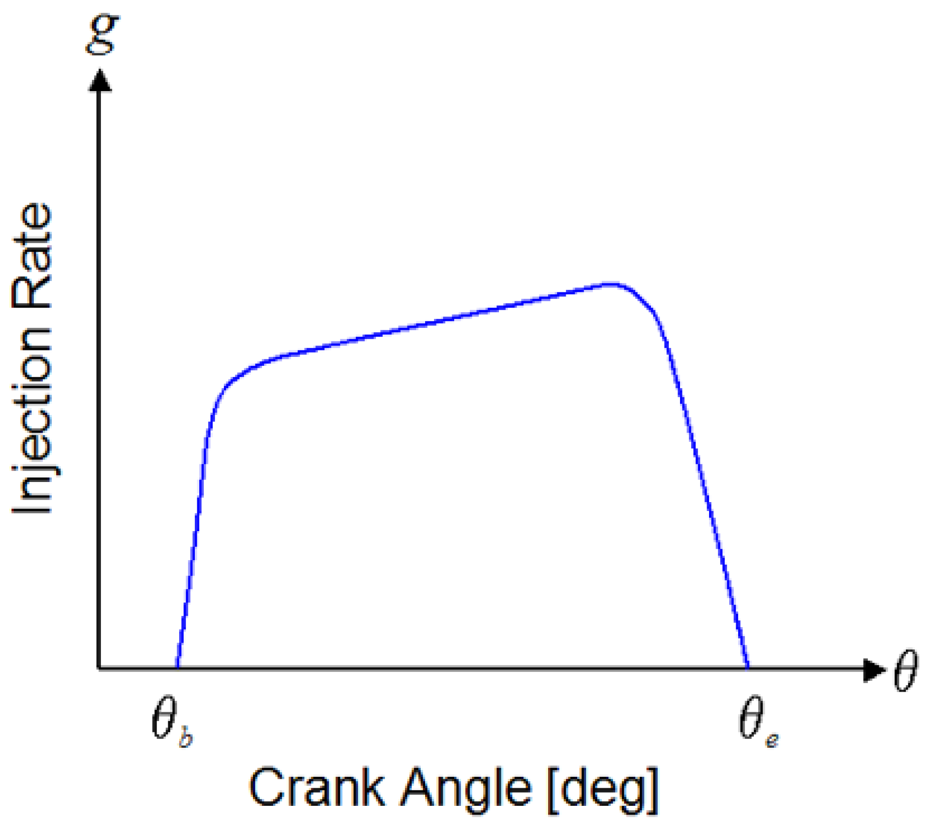
A rectangular injection rate profile is adopted as a first-order approximation of the injection process, consistent with typical common-rail systems operating under stable conditions. While simplified, this approach captures the dominant characteristics of fuel delivery and provides sufficient flexibility for parametric optimisation and sensitivity analysis.
To ensure generality and scalability, the injection rate profile is defined in a dimensionless form and subsequently normalised, as in Figure 1. A scaling factor, s, is introduced to relate the dimensionless profile to the actual injected fuel mass per cycle. The instantaneous injection mass flow, ṁinst, is therefore expressed as [46]:
m . inst = m . cycle × s × g inst
where ṁcycle is the cycle-total fuel flow rate and ginst is the instantaneous normalised injection rate.
Injection duration remains a key parameter governing the temporal characteristics of the injection event; however, in the present framework, both injection pressure and total injected fuel mass are kept constant. Under these conditions, variations in injection duration primarily influence the rate of fuel delivery rather than the overall injected quantity. A shorter injection duration results in a higher instantaneous injection rate, promoting faster energy release and a greater fraction of premixed combustion. Conversely, a longer injection duration spreads the same fuel mass over a wider crank-angle interval, leading to a lower injection rate and a more gradual, diffusion-controlled combustion process.
It should be noted that the present modelling approach assumes constant injection pressure and total injected fuel mass, allowing the isolated investigation of injection duration effects. In practical common-rail systems, variations in injection duration can influence rail pressure dynamics, injector needle behaviour, and backpressure effects, which can, in turn, modify the actual rate-of-injection profile. Therefore, while the present approach is suitable for analysing fundamental trends, further studies incorporating detailed injector dynamics would be beneficial to fully capture real-system behaviour.
In the present study, injection duration is treated as a controllable variable within the optimisation framework. During the initial optimisation phase [44,50], injection duration is adjusted alongside other control parameters—such as SOI, fuel rate, and turbocharger speed—to achieve optimal engine performance and emissions across different operating points. Subsequently, in the sensitivity analysis phase, injection duration is varied around its optimised values to assess its influence on combustion behaviour and performance.
This modelling approach allows injection duration to be interpreted not only as a fuel-delivery parameter but also as a key factor influencing ROI and, indirectly, the in-cylinder mixture-formation process. In a 1D engine model, spray development is not explicitly resolved; instead, its effects are incorporated through phenomenological combustion models that account for ignition delay and the partitioning between premixed and diffusion combustion phases [51,52]. Although a rectangular injection profile simplifies the detailed injector dynamics, it provides a computationally efficient and robust representation of the injection process. This enables the model to capture the first-order influence of injection duration on combustion phasing, heat release characteristics, and overall engine performance.

5.3. Combustion and Heat Transfer Models

Combustion within each cylinder is modelled using a two-zone thermodynamic approach, in which the cylinder contents are divided into burned and unburned regions. The governing equations of mass and energy conservation are solved at each crank angle step, enabling dynamic predictions of pressure, temperature, and heat release [49].
The burned mass fraction is calculated using the Watson combustion model [53], which represents diesel combustion as a combination of three distinct phases: premixed combustion, diffusion combustion, and tail burning. This model provides a physically grounded description of heat release while maintaining computational efficiency, making it suitable for large-scale parametric studies [54]. The burned mass fraction, xb, is expressed as a function of crank angle and ignition delay, incorporating contributions from the different combustion phases [53]:
x b   = f ( θ , Δ θ delay   , p f   , d f   , t f   )
where pf, df and tf represent the mass fractions associated with premixed, diffusion, and tail combustion, respectively. The ignition delay, Δϴdelay, is calculated as a function of fuel properties (e.g., cetane number), in-cylinder pressure and temperature, and injection conditions.
Injection duration is inherently coupled with this combustion model through its influence on fuel delivery timing and mixture preparation. A longer injection duration extends the diffusion combustion phase, allowing fuel to continue being injected after ignition and promoting mixing-controlled combustion. In contrast, shorter injection durations concentrate fuel delivery earlier in the cycle, increasing the fraction of premixed combustion and leading to a sharper heat release profile.
The total heat release rate, dQ/dϴ, is computed from the rate of fuel mass burned [4]:
dQ d θ   = m . fuel   × CV × dx b d θ  
where CV is the calorific value of the fuel. Heat transfer to the cylinder walls, Qw, is modelled using the Woschni correlation [55], which accounts for piston motion, gas velocity, and in-cylinder thermodynamic conditions:
Q w   = h × A w   × ( T g   T w   )
where h is the convective heat transfer coefficient, Aw is the instantaneous heat transfer area of the cylinder walls, Tg is the in-cylinder gas temperature and Tw is the cylinder wall temperature.
This formulation ensures that the interaction between combustion and heat losses is accurately represented, which is essential for predicting engine efficiency and emissions.

5.4. Exhaust Emissions Models

The formation of nitrogen oxides (NOx) is modelled using the extended Zeldovich mechanism [56,57], which describes the thermal formation of nitric oxide (NO) via a set of temperature-dependent chemical reactions. The NOx formation rate is evaluated based on the instantaneous burned-zone temperature, oxygen concentration, and residence time at high temperatures. This approach captures the strong dependence of NOx emissions on peak in-cylinder temperature and combustion phasing, both of which are influenced by injection duration.
Carbon monoxide (CO) emissions are predicted using a combustion-based sub-model that evaluates incomplete oxidation processes within the cylinder. The model accounts for the freezing of radical species (hydrogen (H) and hydroxide (OH)) during expansion, providing a realistic estimate of CO persistence in the exhaust [58].
Unburned hydrocarbon (HC) emissions are estimated using a simplified model based on fuel trapped in the injector sac and nozzle volumes. A fixed fraction of this fuel is assumed to escape oxidation, reflecting experimental observations in diesel engines [59].

5.5. Model Validation and Uncertainty

Model validation is an essential step to ensure the reliability of the simulation results. In the present study, the WAVE model has been calibrated based on engine specifications and established modelling practices for high-speed marine diesel engines. The predicted performance parameters, including brake power, BSFC, and in-cylinder pressure trends, are consistent with typical behaviour reported in the literature for similar engines [60]. Furthermore, the predicted emission levels fall within established regulatory limits [61], supporting the physical plausibility of the model outputs. While detailed experimental validation for the specific engine configuration is not available, the agreement with known performance trends and emission benchmarks provides confidence in the model’s ability to capture the relative variations and sensitivity behaviour analysed in this study.
All simulations are performed using the WAVE one-dimensional engine simulation environment. The model is calibrated based on manufacturer specifications and validated against typical engine performance and emissions trends reported in the literature. As the present study is simulation-based, no physical measurement instrumentation is involved. Instead, model accuracy is ensured through physically based sub-models, including combustion, heat transfer, and emissions formation models. Uncertainty is therefore associated with modelling assumptions, particularly in the representation of the injection rate profile and simplified emissions chemistry. Despite these limitations, the model is considered suitable for capturing relative trends and sensitivity behaviour, which constitute the primary objective of this study, rather than absolute prediction.

6. Results and Discussions

6.1. Engine Performance and Exhaust Emissions

The effect of injection duration on engine performance and exhaust emissions is evaluated through a combined sensitivity and parametric analysis around the optimised operating conditions, with results presented in Figure 2, Figure 3, Figure 4, Figure 5, Figure 6 and Figure 7 for four engine loads (100%, 75%, 50%, and 25%). All parameters are normalised with respect to the optimised reference case, allowing for a direct comparison of deviations across operating conditions.
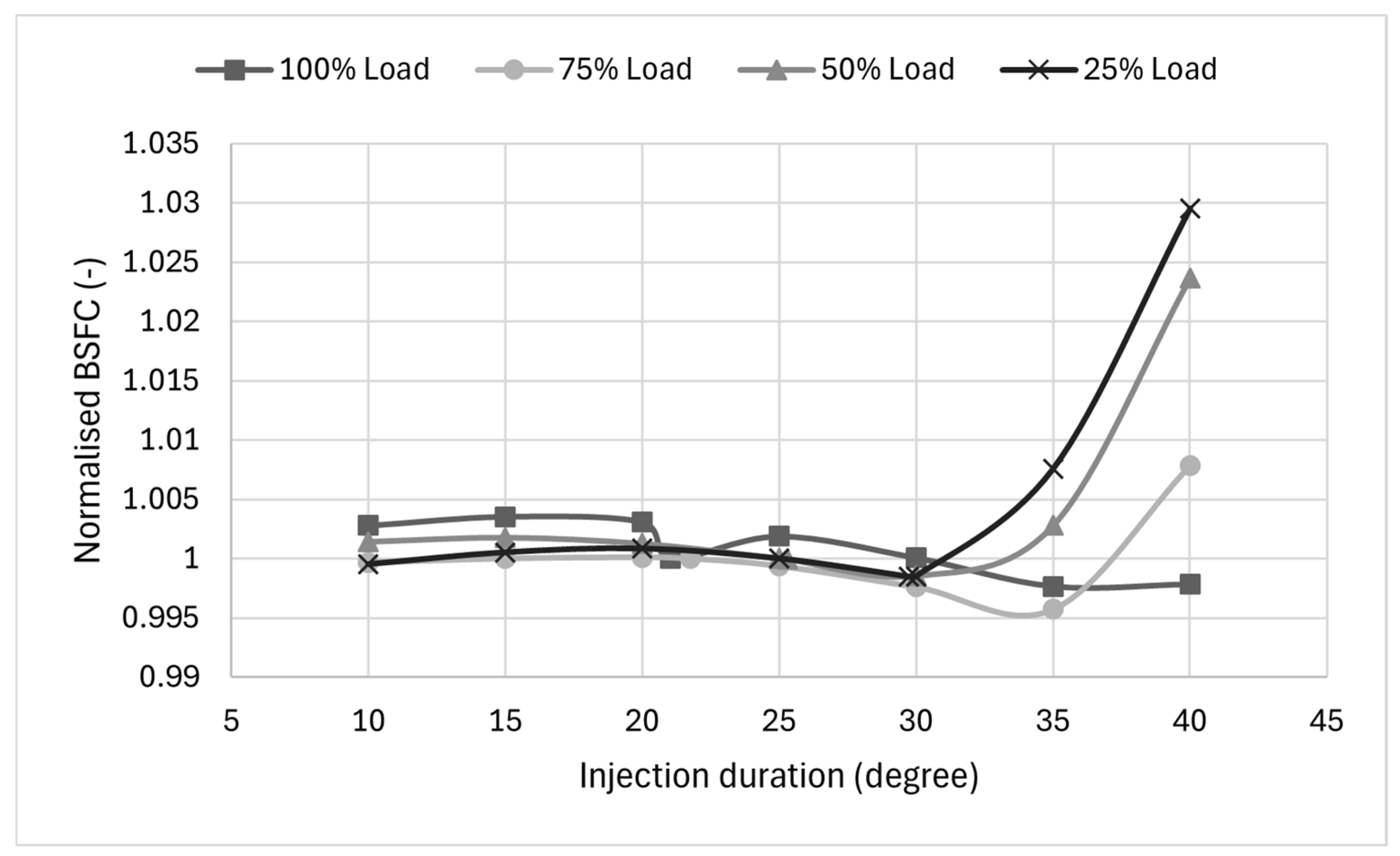
Figure 2 shows the variation in normalised BSFC as a function of injection duration across four engine operating points, revealing a nonlinear, load-dependent behaviour. For all operating conditions, BSFC remains nearly constant over the injection duration range of 10° to 30° CA, with deviations of approximately ±0.2–0.3%, indicating a robust operating region around the optimised solution. The minimum BSFC is generally observed between 30° and 35° CA, particularly at medium and high loads, corresponding to near-optimal combustion phasing. Beyond this range, a clear divergence between load conditions is observed. At full load, BSFC remains relatively stable across the entire range, with variations within ±0.3%, indicating limited sensitivity to injection duration. In contrast, at part-load conditions, BSFC increases significantly at longer injection durations. At 25% load, BSFC rises sharply beyond 30° CA, reaching approximately +3% at 40° CA, while at 50% and 75% loads, the increase is approximately +2.3% and +1%, respectively. This behaviour is attributed to the reduction in instantaneous injection rates at longer injection durations, which weakens spray momentum and air–fuel mixing, particularly under low-load conditions where in-cylinder temperatures and turbulence levels are lower. As a result, combustion shifts toward a more diffusion-controlled regime, delaying heat release and reducing thermodynamic efficiency, thereby increasing fuel consumption. At higher loads, improved mixing conditions and higher temperatures mitigate this effect, resulting in a more stable BSFC response. Overall, the results demonstrate that while injection duration has a limited impact within the optimal range, deviations toward longer durations lead to a pronounced deterioration in efficiency, particularly under part-load operation.
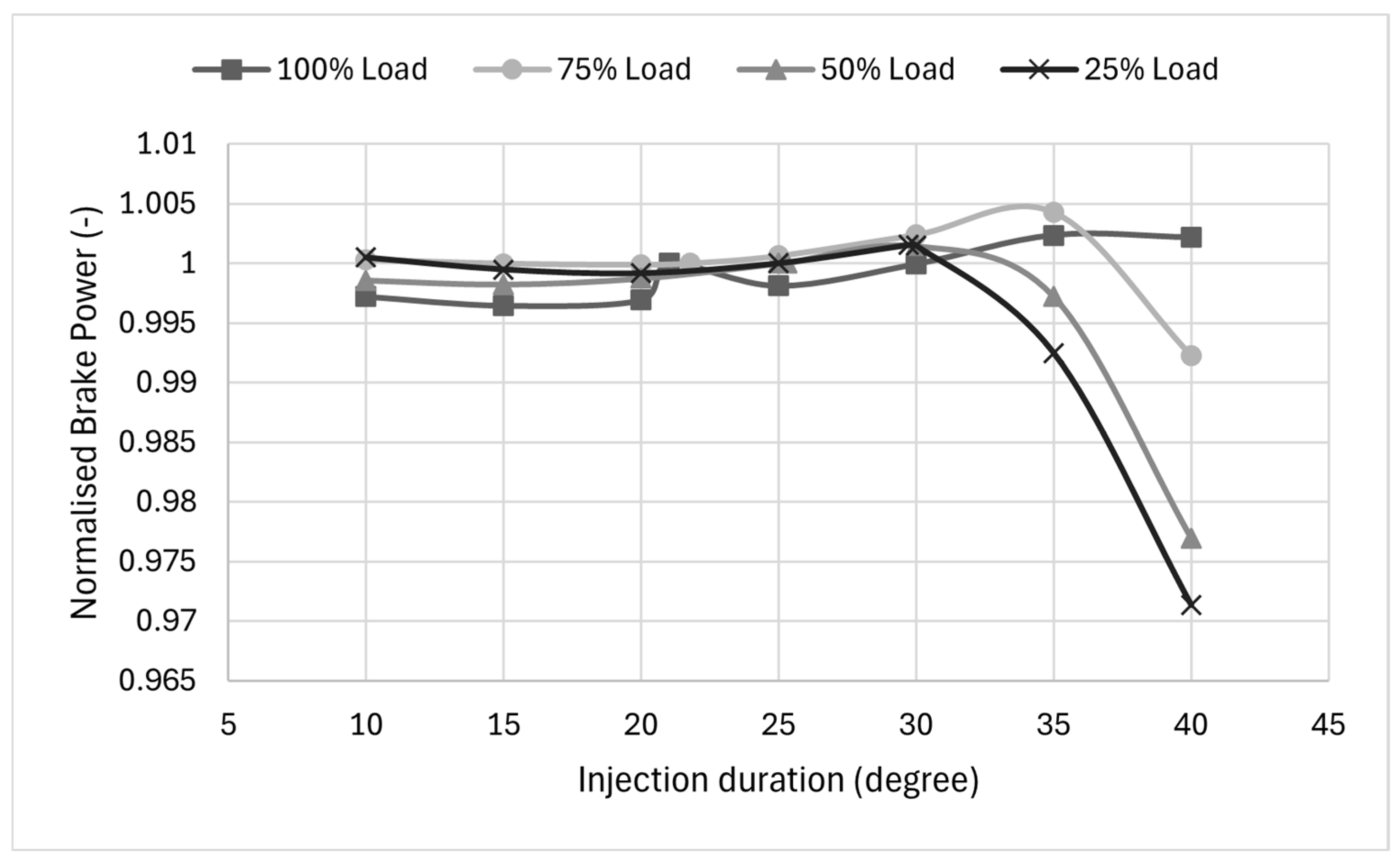
Figure 3 presents the variation of normalised brake power with injection duration for different engine loads. Similar to the BSFC trends, brake power remains relatively stable within the injection duration range of 10° to 30° CA, with deviations generally within ±0.2–0.3% across all loads. This confirms that the optimised injection duration lies within a broad plateau region, where combustion phasing remains close to optimal and the engine can maintain its power output despite moderate variations in injection duration.
However, beyond this range, a clear deterioration in brake power is observed, particularly at part-load conditions. At 25% load, brake power decreases sharply beyond 30° CA, reaching a reduction of approximately −2.9% at 40° CA, representing the most pronounced sensitivity among all operating conditions. A similar trend is observed at 50% load, where brake power decreases by approximately −2.3%, whereas at 75% load the reduction is more moderate, around −0.8%. In contrast, at full load (100%), brake power remains largely unaffected, with only a slight increase of approximately +0.2% at higher injection durations.
This behaviour is consistent with the BSFC trends and can be explained by the underlying combustion dynamics. As injection duration increases while maintaining constant fuel mass, the instantaneous injection rate decreases, resulting in weaker spray penetration and reduced air–fuel mixing efficiency. This leads to a shift from premixed-dominated combustion toward a more diffusion-controlled regime, where combustion occurs more slowly and over a longer crank-angle interval.
At part-load conditions, where in-cylinder temperatures and turbulence levels are inherently lower, this reduction in mixing efficiency has a more significant impact, leading to delayed heat release and reduced effective pressure development near top dead centre. Consequently, a larger fraction of the combustion energy is released during the expansion stroke, reducing the work extracted from the cycle and resulting in a noticeable drop in brake power.
At higher loads, however, the elevated temperatures and enhanced in-cylinder turbulence promote faster chemical reactions and improved mixing, mitigating the negative effects of reduced injection rates. As a result, the engine exhibits a more stable brake power response even at extended injection durations.
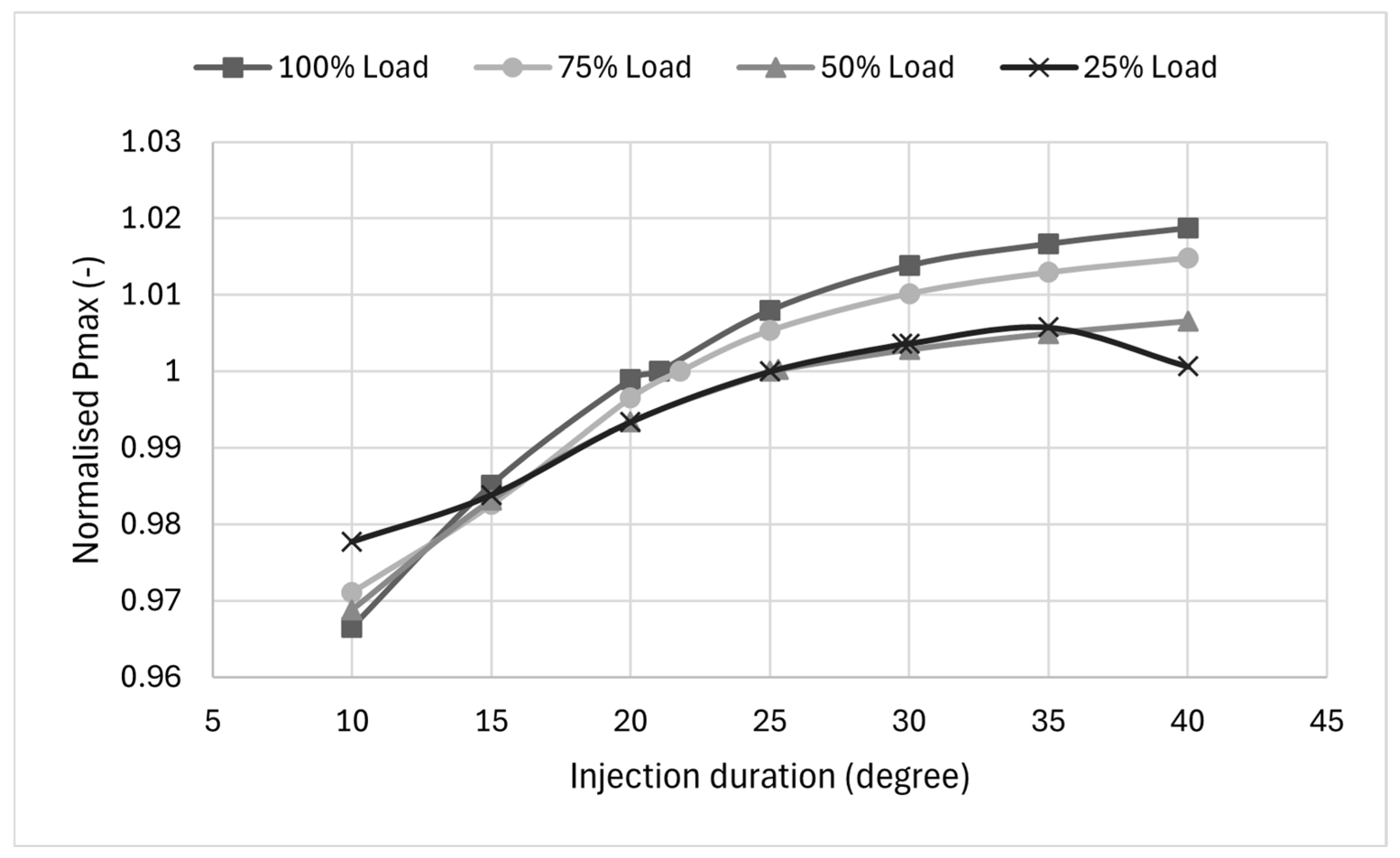
Figure 4 presents the variation of normalised maximum in-cylinder pressure (Pmax) as a function of injection duration for different engine loads. In contrast to the trends observed for BSFC and brake power, Pmax exhibits a monotonic increase with injection durations across all operating conditions, particularly within the range of 15° to 35° CA.
At shorter injection durations (around 10° CA), Pmax is noticeably lower than the reference condition, with reductions of approximately −3.5% at full load and −2–3% at part-load conditions. This behaviour can be attributed to the higher instantaneous injection rate associated with shorter durations, which promotes rapid premixed combustion but may lead to an earlier completion of heat release and reduced pressure development during the expansion phase.
As injection duration increases, Pmax rises steadily for all loads, reaching maximum values at longer durations. At 100% load, Pmax increases by approximately 1.8% at 40° CA, while at 75% load, the increase is approximately 1.5%. At 50% load, the increase is more moderate, reaching approximately +0.6%, whereas at 25% load, Pmax peaks at around +0.5% at 35° CA, followed by a slight decrease at 40° CA.
This trend reflects the shift in combustion characteristics associated with longer injection durations. As the injection event is extended, fuel delivery continues into a longer crank-angle interval, sustaining heat release over a longer crank-angle interval. This results in higher cumulative pressure levels, particularly during the late combustion phase, thereby increasing maximum pressure.
However, despite the increase in peak pressure, this does not translate into improved engine performance, as previously observed in the brake power and BSFC results. The additional pressure generated at longer injection durations occurs later in the cycle, when the piston is already moving downwards, reducing the effectiveness of the pressure in producing useful work. This explains the apparent contradiction between increasing Pmax and decreasing brake power at extended injection durations.
At low load, the behaviour differs slightly, with Pmax showing a plateau or slight reduction at the longest injection duration. This can be attributed to weaker combustion intensity and reduced heat release efficiency under these conditions, where poor air–fuel mixing limits the ability to sustain high pressure levels despite extended injection.
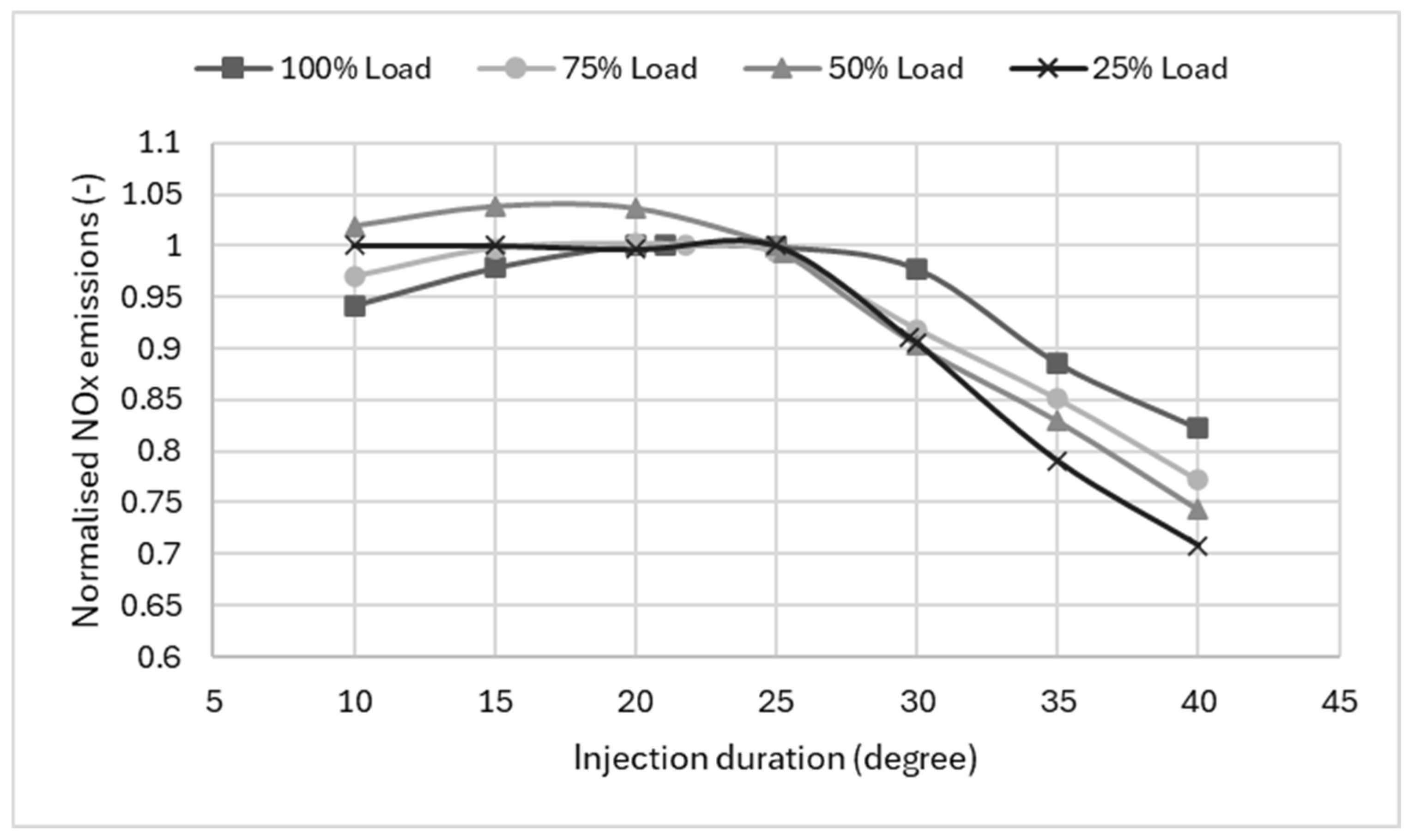
Figure 5 presents the variation of normalised NOx emissions as a function of injection duration for different engine loads. In contrast to the trends observed for BSFC and brake power, NOx emissions decrease with increasing injection durations, particularly beyond 25° CA, highlighting a clear trade-off between efficiency and emissions.
Within the range of 10° to 25° CA, NOx emissions remain relatively close to the reference condition, with only minor variations (within approximately ±2–4%), indicating that combustion temperature and heat release characteristics are largely preserved near the optimised injection duration. A slight increase in NOx is observed at intermediate durations (around 15–20° CA), particularly at medium loads, which can be attributed to enhanced premixed combustion leading to higher peak temperatures.
However, as injection durations increase beyond 25–30° CA, NOx emissions decrease significantly across all loads. At 100% load, NOx decreases to approximately 0.82 (−18%) at 40° CA, while at 75% load, the reduction reaches approximately −25%. The trend is even more pronounced at lower loads, with NOx reductions of approximately −28% at 50% load and up to −30% at 25% load at the longest injection duration.
This behaviour can be directly linked to the changes in combustion characteristics induced by longer injection durations. As previously discussed, increasing injection duration reduces the instantaneous injection rate, leading to weaker spray penetration and slower air–fuel mixing. This results in a shift from premixed combustion toward a more diffusion-controlled combustion regime, characterised by lower peak flame temperatures and more distributed heat release. This behaviour is consistent with the classical NOx–temperature relationship governed by the extended Zeldovich mechanism, in which NOx formation increases exponentially with peak flame temperature. Consequently, even moderate reductions in peak temperature resulting from prolonged, distributed heat release can lead to significant decreases in NOx emissions.
Since NOx formation is highly sensitive to peak combustion temperature and oxygen availability, the reduction in temperature associated with extended heat release leads to a significant decrease in thermal NOx formation. Additionally, the delayed combustion phasing reduces the residence time of high-temperature gases, further limiting NOx production.
The stronger sensitivity observed at part-load conditions is consistent with the lower baseline temperatures and reduced turbulence levels, which amplify the effect of the reduced injection rate and extended combustion duration. As a result, even small changes in injection characteristics lead to more pronounced reductions in NOx emissions.
The magnitude of NOx reduction observed in this study (up to approximately 30% at low load) is consistent with values reported in the literature for similar variations in injection characteristics, where reductions of 15–30% are typically associated with extended injection duration and delayed combustion phasing. The slightly higher sensitivity observed at part-load conditions in the present results can be attributed to the combined effects of lower in-cylinder temperatures and reduced mixing intensity, which amplify the impact of injection rate variations.
However, this reduction in NOx is accompanied by the previously observed penalties in BSFC and brake power, as well as the expected increase in incomplete combustion products (CO and HC). This highlights the fundamental trade-off between NOx emissions and engine efficiency, where conditions that reduce peak temperature and NOx formation simultaneously degrade combustion efficiency.
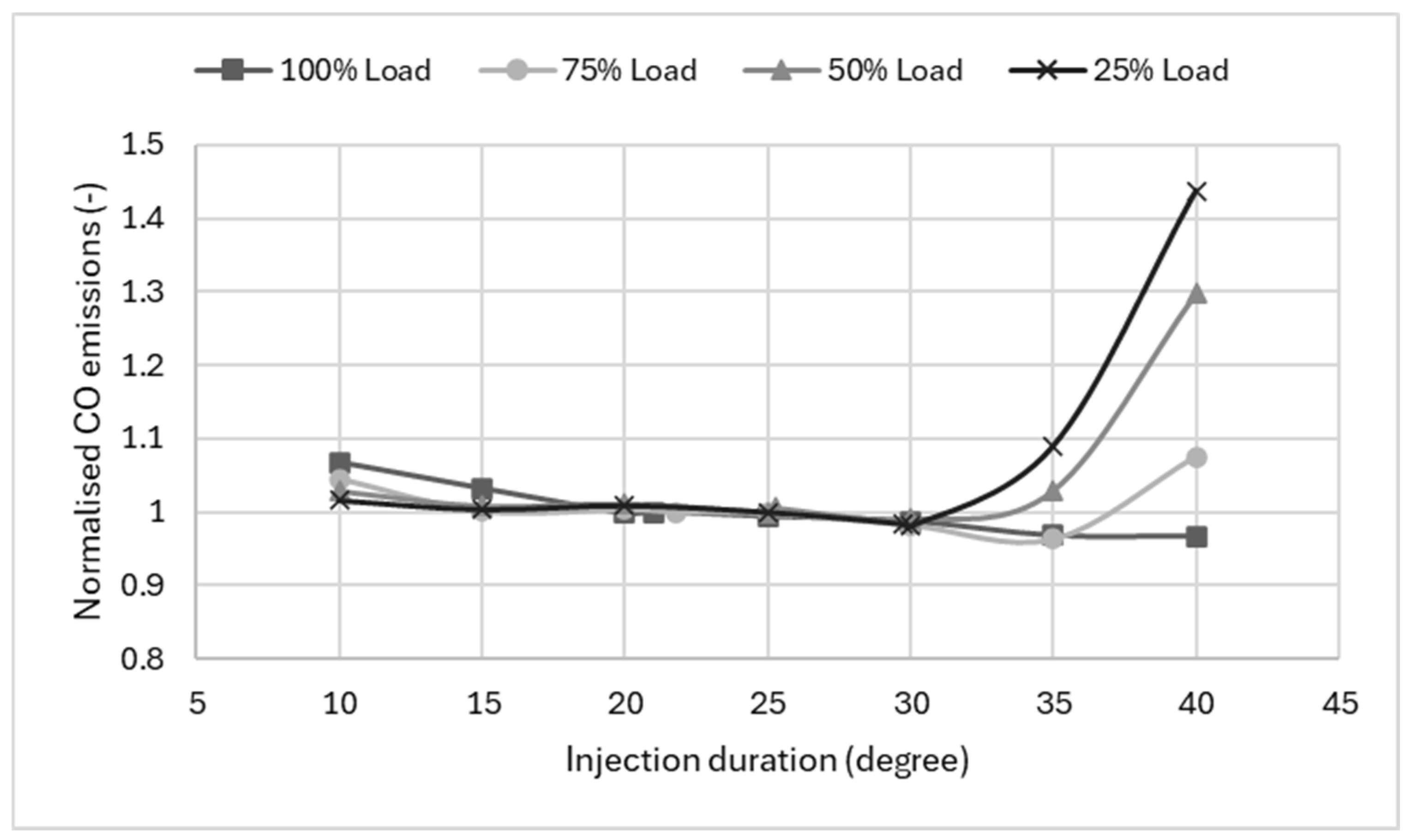
Figure 6 presents the variation of normalised CO emissions as a function of injection duration for different engine loads. In contrast to NOx emissions, CO shows a clear increase at longer injection durations, particularly beyond 30° CA, highlighting the typical trade-off between complete combustion and low-temperature operation.
Within the range of 10° to 30° CA, CO emissions remain relatively stable and close to the reference condition for all loads, with only minor deviations (within approximately ±2–5%). This indicates that combustion efficiency is largely preserved near the optimised injection duration, where fuel–air mixing and oxidation processes remain effective.
However, as injection durations increase beyond this range, CO emissions rise significantly, especially under part-load conditions. At 25% load, CO increases sharply beyond 30° CA, reaching approximately +45% at 40° CA, representing the most pronounced sensitivity among all operating points. Similarly, at 50% load, CO emissions increase by approximately 30%, while at 75% load, the increase is more moderate at around 10%. In contrast, at full load (100%), CO emissions remain relatively stable, with only a slight variation around the reference value, indicating a lower sensitivity to injection duration.
This behaviour is directly linked to the deterioration of combustion efficiency associated with longer injection durations. As previously discussed, increasing injection duration reduces the instantaneous injection rate, weakening spray atomisation and air entrainment. This leads to poorer mixture formation and a greater prevalence of locally rich regions, particularly in low-temperature and low-turbulence environments.
The increase in CO emissions reflects a shift from kinetically controlled combustion to mixing-limited combustion, in which oxidation rates are governed by local air–fuel mixing rather than chemical kinetics. Under these conditions, insufficient oxygen availability and reduced mixing rates limit the conversion of CO to carbon dioxide (CO2), leading to the accumulation of intermediate combustion products.
As a result, combustion shifts toward a more diffusion-controlled regime, where oxidation of intermediate species is less complete. The extended injection event also delays combustion completion, reducing the available time for CO to oxidise to CO2 before exhaust valve opening. These effects are especially pronounced at part-load conditions, where lower in-cylinder temperatures further limit oxidation kinetics.
The magnitude of CO increase observed in this study (up to approximately 45% at low load) is consistent with trends reported in the literature, where extended injection durations and reduced injection rates are associated with significant increases in incomplete combustion products under mixing-limited conditions. The higher sensitivity observed at part load is also consistent with previous findings, which show that reduced turbulence and lower temperatures amplify oxidation limitations.
The relatively stable CO behaviour at high load can be attributed to the higher combustion temperatures and enhanced turbulence, which promote more complete oxidation even when the injection duration is extended. This mitigates the formation of incomplete combustion products despite the reduction in injection rate.
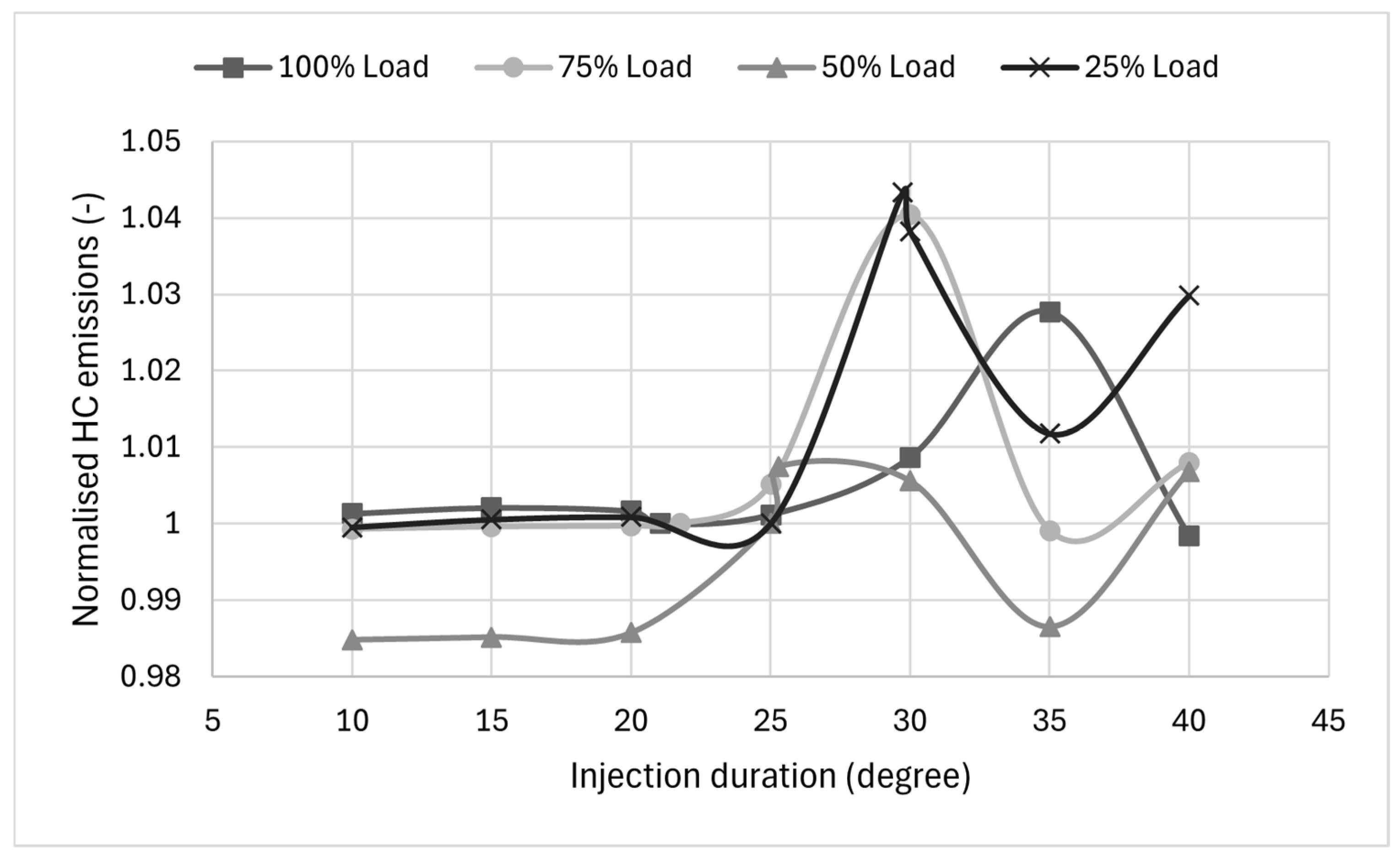
Figure 7 presents the variation of normalised HC emissions as a function of injection duration for different engine loads. Compared to CO emissions, HC exhibits a more complex and non-monotonic behaviour, reflecting the combined influence of mixture formation, combustion completeness, and local quenching effects.
Within the injection duration range of 10° to 25° CA, HC emissions remain relatively close to the reference condition for all loads, with only minor deviations (within approximately ±1–2%). This indicates that, near the optimised injection duration, the combustion process is sufficiently stable to ensure effective oxidation of unburned hydrocarbons.
However, as injection duration increases beyond this range, HC emissions show a pronounced sensitivity, particularly at part-load conditions. At 25% load, HC emissions increase sharply, reaching a peak of approximately +4–4.5% at 30° CA, followed by a slight reduction at 35° CA and a subsequent increase again at 40° CA. A similar trend is observed at 75% load, where HC peaks around +4% at 30° CA, then decreases and partially recovers at longer durations. At 50% load, the behaviour differs slightly, with HC initially decreasing below the reference value at intermediate durations (around −1.5% at 35° CA) before increasing again at longer injection durations.
At full load (100%), HC emissions remain comparatively stable across the entire range, with only moderate variations, reaching a maximum of approximately +2.7% at 35° CA, followed by a decrease at 40° CA. This indicates that high-temperature conditions promote more complete oxidation, even when the injection duration is extended.
The observed behaviour can be explained by the interaction between injection characteristics and local combustion conditions. Increasing injection duration reduces the instantaneous injection rate, resulting in weaker spray atomisation and lower air–fuel mixing efficiency. This promotes the formation of locally rich or over-lean zones, particularly at part load, where turbulence intensity and temperature are lower. These regions are more prone to incomplete combustion and flame quenching, resulting in higher HC emissions.
Similar to CO formation, HC emissions are strongly influenced by mixing-limited combustion conditions, in which incomplete oxidation occurs due to insufficient local temperatures and oxygen availability. In this regime, fuel fragments and partially oxidised species can escape complete combustion, contributing to increased HC levels.
The peak observed around 30° CA suggests a transition between kinetically controlled combustion and mixing-limited combustion regimes, where the combined effects of delayed combustion, reduced mixing efficiency, and local quenching are maximised. The subsequent temporary reduction in HC emissions at intermediate injection durations (e.g., around 35° CA) may be attributed to a transitional combustion regime, in which a slight extension of the heat release process increases the residence time of partially oxidised species at moderate temperatures, promoting more complete oxidation. Beyond this point, further increases in injection duration lead to strongly mixing-limited combustion, reducing oxidation efficiency and causing HC emissions to rise again. While such non-monotonic behaviour is less commonly reported compared to the typically monotonic trends observed in diesel engines, similar transitional behaviour has been identified in studies where combustion shifts between kinetically controlled and mixing-limited regimes. The relatively moderate magnitude of HC variation (within approximately ±5%) compared to that of CO is also consistent with the literature, which shows that HC formation is more sensitive to local quenching and crevice effects than to global combustion efficiency alone.
The stronger sensitivity of HC emissions at part-load conditions is consistent with the trends observed for CO emissions and brake power, confirming that low-load operation is particularly vulnerable to deviations in injection duration. Under these conditions, reduced in-cylinder temperature and weaker turbulence limit oxidation kinetics, amplifying the impact of suboptimal injection strategies.
The results demonstrate that HC emissions are highly sensitive to injection duration, particularly outside the optimised range. While moderate variations have a limited impact, extended injection durations lead to increased incomplete combustion, reinforcing the importance of maintaining injection duration within the optimal window identified in Section 3.
The observed trends are consistent with previous experimental and numerical studies on injection duration and rate shaping. For example, it has been reported that increasing injection duration leads to a reduction in NOx emissions (typically 15–25%) due to lower peak combustion temperatures, accompanied by increases in CO and HC emissions of up to 30–50% under part-load conditions [39]. Similarly, it has been demonstrated that extended injection duration promotes a shift toward diffusion-controlled combustion, resulting in prolonged heat release and reduced combustion efficiency [37].
In the present study, NOx emissions reductions of up to 30% and CO emissions increases of up to 45% at low load are observed, in good agreement with the magnitudes reported in the literature. The slightly higher sensitivity observed in the present results can be attributed to the simplified injection profile and the strong influence of part-load conditions, where reduced turbulence and lower temperatures amplify mixing limitations.
Overall, the results demonstrate that injection duration governs a critical coupling between combustion phasing, efficiency, and emissions formation, and cannot be treated as an independent tuning parameter. The sensitivity analysis confirms that the optimised injection duration identified in Section 3 corresponds to a physically meaningful operating point, where the balance between premixed and diffusion combustion leads to smooth heat release, efficient energy conversion, and controlled emissions. Deviations from this optimum—particularly toward longer injection durations—systematically disrupt this balance, resulting in delayed heat release, reduced brake power, increased fuel consumption, and higher levels of incomplete combustion products (CO and HC), despite the benefit of reduced NOx emissions.
In conventional diesel engines, NOx and particulate matter (PM) represent the primary regulated emissions, typically exhibiting a well-known trade-off. While PM is not explicitly modelled in the present study, its formation is strongly linked to locally rich regions and incomplete combustion processes. The observed increase in CO and HC emissions at extended injection durations indicates deteriorated oxidation conditions, which are also favourable for soot precursor formation. Therefore, the results suggest that the reduction in NOx achieved at longer injection durations would likely be accompanied by increased PM emissions, consistent with established diesel combustion behaviour.
Importantly, the magnitude of these effects is strongly load-dependent, with part-load conditions exhibiting significantly higher sensitivity due to lower in-cylinder temperatures and weaker mixing. From a system-level perspective, this behaviour reflects the propagation of a local control variable across multiple interconnected subsystems, including fuel injection, air management, and combustion. Such interactions highlight that injection duration influences engine behaviour beyond a single physical mechanism, affecting the overall system response through coupled thermodynamic and fluid-dynamic processes. This highlights the necessity of load-adaptive injection control strategies, especially in marine applications where engines operate over wide load ranges. From a practical perspective, the findings provide clear evidence that maintaining injection duration within a narrow optimal window is essential for achieving robust engine performance and emissions compliance, while the presented framework offers a systematic approach for identifying and validating such operating conditions.
It should be noted that the emission predictions in the present study are based on simplified chemical sub-models, including the extended Zeldovich mechanism for NOx formation and reduced-order formulations for CO and HC. While these models are widely used and provide a reasonable representation of emission trends, they inherently involve simplifications in the underlying reaction kinetics. The predicted emission levels are consistent with established regulatory limits and have been cross-checked against typical marine engine benchmarks reported in the literature, where combined NOx and HC emissions and CO emissions are constrained according to the values presented in [61]. As a result, the present analysis is considered reliable for capturing relative variations and sensitivity trends associated with changes in injection duration. It should be emphasised that the present analysis focuses on relative trends rather than absolute emission magnitudes; therefore, the interpretation of results is centred on physical consistency and comparative behaviour rather than direct quantitative prediction. Nevertheless, the absolute emission values should be interpreted with caution, and further validation against detailed experimental data across a wider range of operating conditions would be beneficial to confirm the quantitative accuracy of the predictions.

6.2. Heat Release Rate Analysis

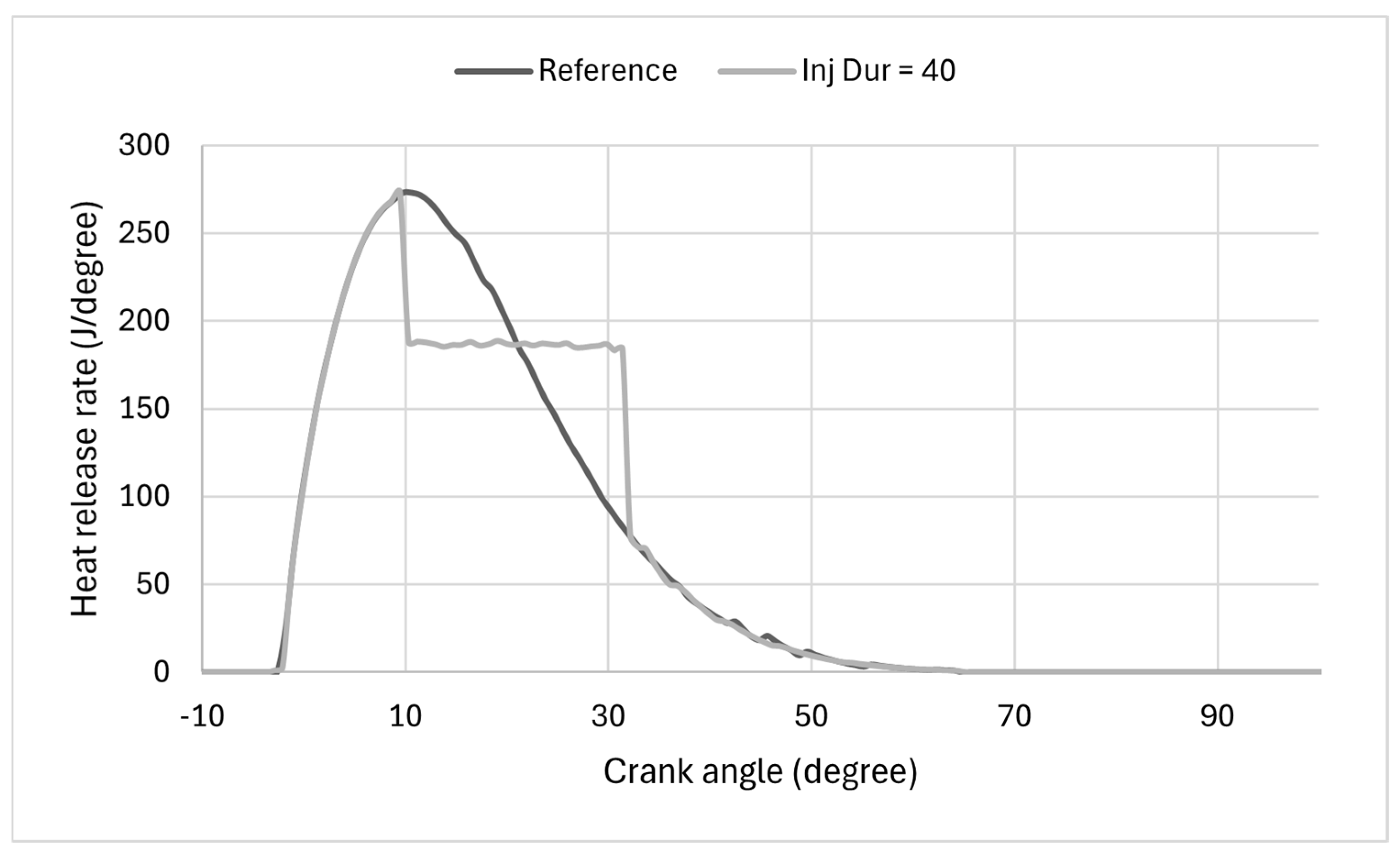
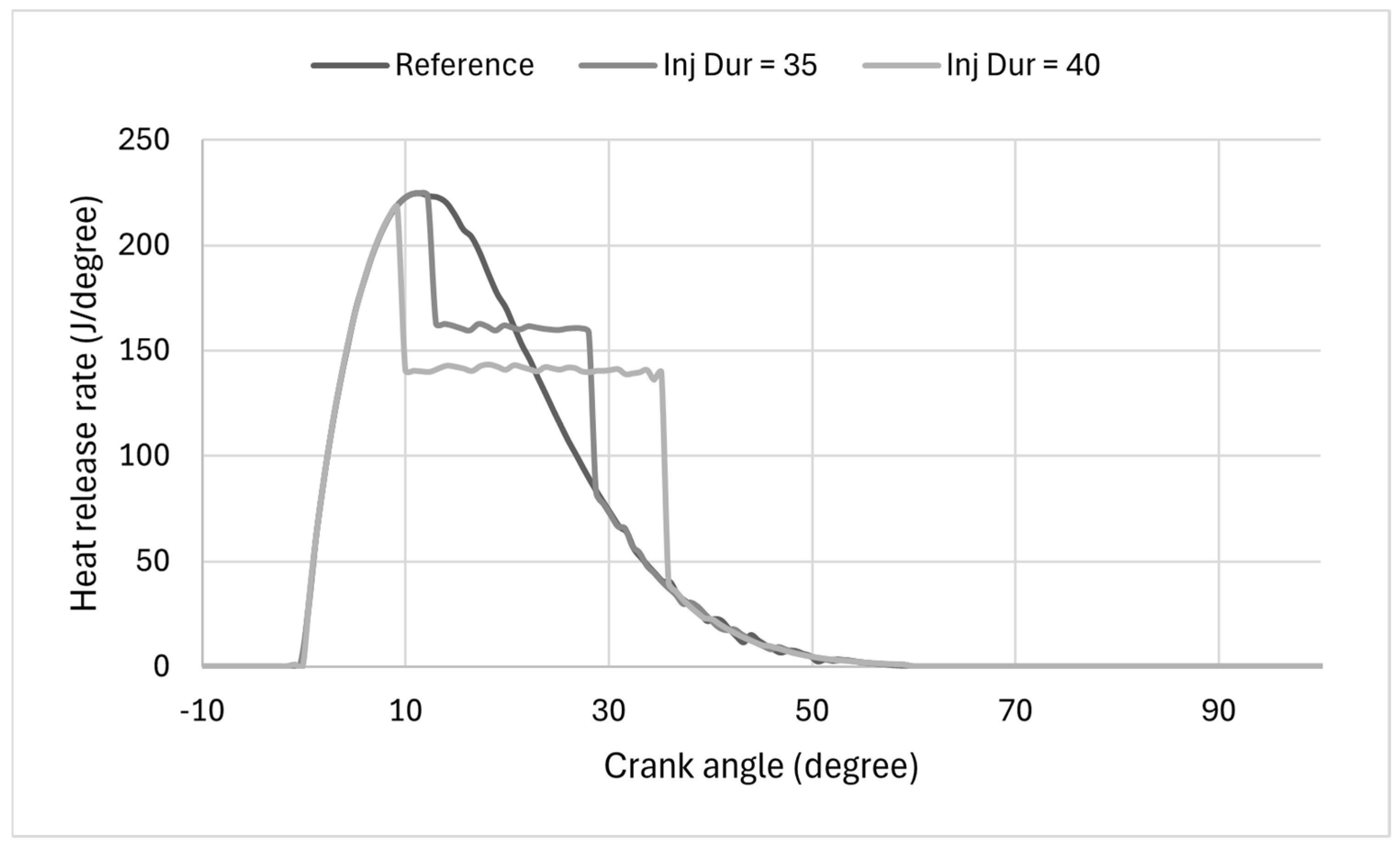
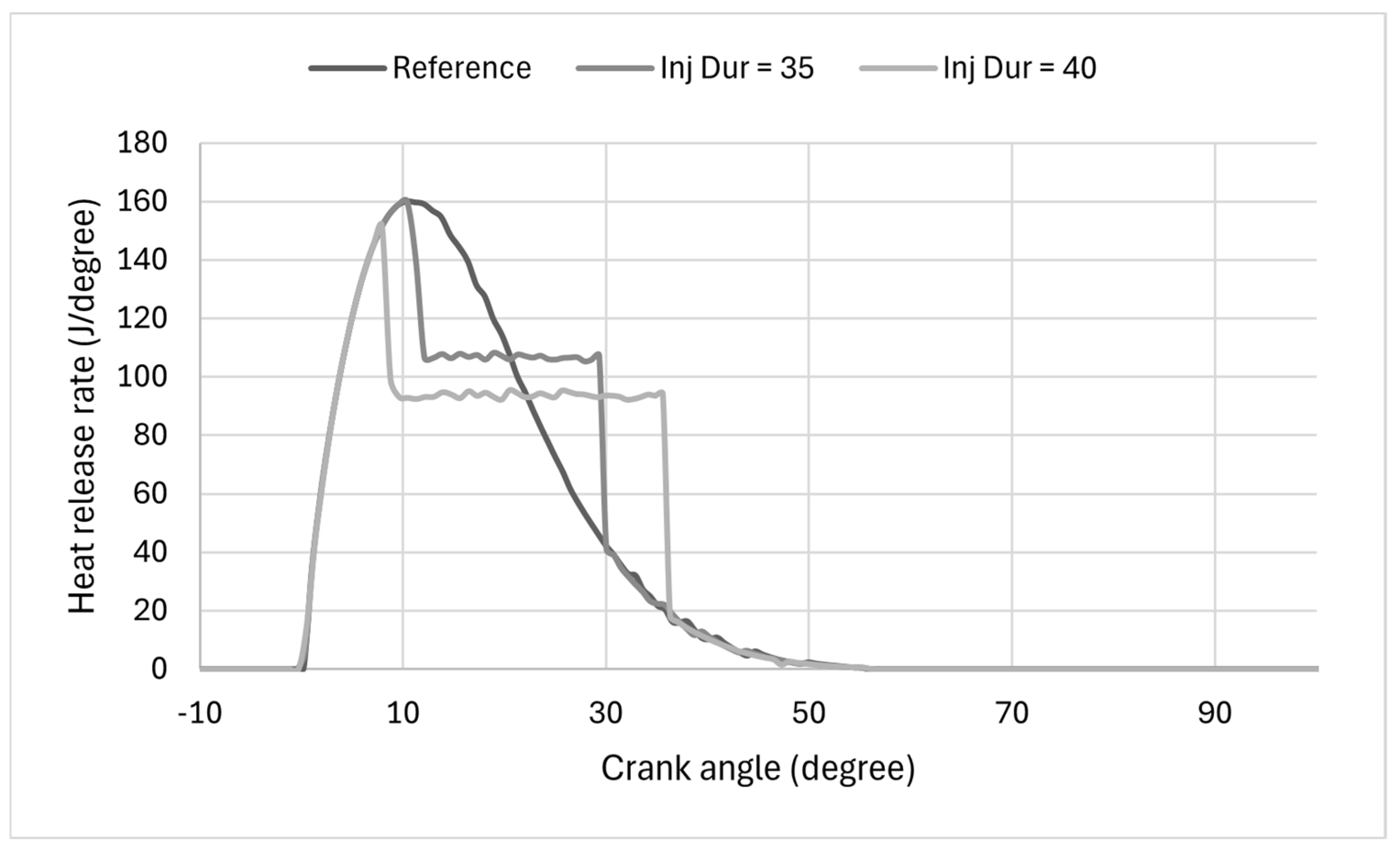
The effect of injection duration on combustion characteristics is further analysed through the HRR profiles at different engine loads, as shown in Figure 8, Figure 9, Figure 10 and Figure 11. The comparison between the optimised reference case and extended injection durations (35° and 40° CA) reveals a consistent trend across all loads and highlights important load-dependent sensitivities.
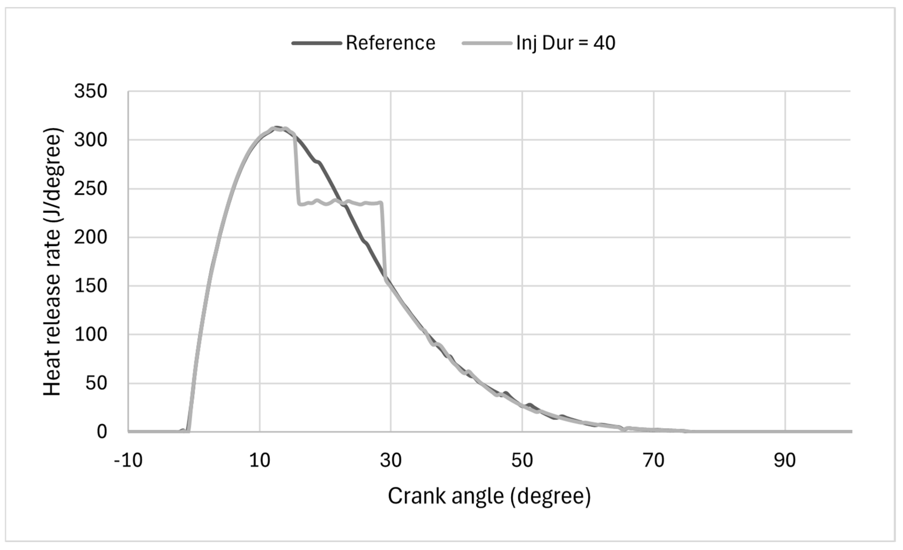
Figure 8 compares the HRR profiles at the optimised injection duration (reference case) and an extended injection duration of 40° CA at 100% engine load. The reference case exhibits a smooth, well-structured HRR profile, characterised by a sharp premixed combustion peak followed by a continuous, gradually decaying diffusion phase. This behaviour indicates efficient combustion phasing at full load, with fuel injection, mixture formation, and heat release well synchronised.
In contrast, the extended injection duration significantly alters the combustion pattern at this high-load condition. While the initial premixed peak remains comparable in magnitude, the subsequent HRR profile becomes non-smooth, exhibiting a pronounced plateau-like region. This flattening indicates that heat release is sustained over a longer crank-angle interval rather than decaying progressively. The transition between premixed and diffusion combustion becomes less distinct, indicating a disruption in the natural progression of combustion.
This non-smooth behaviour is primarily attributed to the reduced ROI associated with longer injection durations. With the same injected fuel mass distributed over a wider crank-angle interval, fuel spray momentum and atomisation quality are reduced, leading to slower air–fuel mixing. As a result, a larger fraction of the combustion shifts toward a mixing-controlled (diffusion-dominated) regime, where heat release is governed by the rate of mixing rather than rapid premixed combustion.
At 100% load, this effect becomes more pronounced due to the higher fuelling rate and increased in-cylinder pressures, which amplify the sensitivity of combustion to injection characteristics. The extended injection also causes temporal overlap between injection and combustion, sustaining heat release well into the expansion stroke. This leads to the observed plateau and delayed decay of the HRR curve, indicating less efficient, less coherent combustion than in the optimised case.
At 75% load, a similar trend is observed, although the impact of extending the injection duration is slightly less pronounced than at full load, as shown in Figure 9. The reference case again shows a smooth, well-defined HRR profile, with a clear premixed combustion peak followed by a progressively decaying diffusion phase, indicating stable, well-phased combustion under part-load conditions.
When the injection duration is increased to 40° CA, the HRR profile exhibits noticeable deviations. The premixed peak remains largely unchanged in magnitude, suggesting that the initial ignition and early combustion processes are still governed by similar thermodynamic conditions. However, the subsequent heat release becomes less smooth and more extended, forming a flattened plateau region between approximately 10° and 30° CA. This behaviour reflects a shift toward a more pronounced mixing-controlled combustion regime.
Compared to the 100% load case, the plateau at 75% load is somewhat less intense and slightly more stable, due to the lower overall fuelling rate and reduced in-cylinder pressures. These conditions moderate the sensitivity of combustion to injection duration, allowing for slightly better mixing even when the injection event is prolonged. Nevertheless, the extended injection still results in a reduction in the instantaneous injection rate, weakening spray momentum and slowing fuel–air mixing.
Additionally, the longer injection duration introduces a greater overlap between injection and combustion, extending heat release further into the expansion stroke. This results in a delayed and less coherent decay of the HRR curve compared to the reference case. While the overall combustion remains stable, the reduced smoothness and prolonged heat release indicate a departure from optimal combustion phasing.
As shown in Figure 10, the influence of injection duration on the HRR profile at 50% load becomes more pronounced in terms of combustion smoothness and stability, even though the overall heat release levels are lower than at higher loads. The reference case continues to exhibit a well-defined, smooth HRR evolution, with a clear premixed peak followed by a gradual, continuous decay, indicating stable combustion phasing under mid-load conditions.
However, when the injection duration is increased to 35° and 40° CA, the HRR profiles begin to show noticeable irregularities and loss of smoothness, more evident than at higher loads. In both cases, the premixed peak remains relatively similar in magnitude, but the subsequent heat-release phase becomes increasingly distorted and less coherent, with the appearance of flattened, slightly oscillatory plateau regions. This behaviour reflects a stronger disruption in the transition between premixed and diffusion combustion phases. The observed flattening and oscillations in the HRR profiles indicate a loss of combustion coherence, in which heat release is no longer dominated by a well-defined premixed phase but is instead controlled by spatially non-uniform mixing processes. Under these conditions, local variations in equivalence ratio, delayed ignition of fuel pockets, and intermittent oxidation result in uneven heat release rates, leading to oscillations in the HRR profile. This behaviour is consistent with a transition toward strongly mixing-limited combustion, particularly under part-load conditions where turbulence intensity and temperature are insufficient to sustain uniform combustion.
The observed fluctuations and irregularities in the HRR profiles at extended injection durations are therefore attributed to physical combustion phenomena rather than numerical artefacts. To ensure this, the simulation time step and solver settings are verified to yield stable, repeatable results, confirming that the observed behaviour reflects underlying physical processes rather than solver-induced artefacts.
Unlike the high-load cases (100% and 75%), where the longer injection duration mainly produced a smoother but extended plateau, at 50% load, the HRR for both 35° and 40° injection durations exhibits clear non-uniformities and fluctuations during the diffusion phase. This indicates that the combustion process becomes more sensitive to injection characteristics at intermediate loads, where lower in-cylinder temperatures and pressures reduce the robustness of fuel–air mixing and combustion stability.
The reduced instantaneous injection rate associated with longer injection durations further weakens spray penetration and atomisation, leading to slower, less homogeneous mixture formation. As a result, combustion becomes more mixing-limited and locally uneven, which is reflected in the irregular HRR shape. Additionally, the extended injection duration increases the overlap between injection and combustion, prolonging heat release into the expansion stroke and contributing to the observed lack of smoothness.
At 25% engine load, as in Figure 11, the effect of extending injection duration on the HRR profile is the most pronounced among all operating conditions. The reference case still shows a recognisable, relatively smooth combustion pattern, with a distinct premixed peak followed by a continuous decay during the diffusion phase. However, compared with higher loads, the absolute HRR level is lower, reflecting the reduced fuelling rate and the weaker thermodynamic environment at low load.
When the injection duration is increased to 35° and 40° CA, the HRR profile becomes markedly less smooth and more distorted, confirming that low-load combustion is highly sensitive to deviations from the optimised injection setting. Although the initial premixed peak remains present, the subsequent heat release no longer decays progressively. Instead, the HRR develops an extended, flattened plateau with visible oscillations, particularly in the 40° CA case, indicating an increasingly unstable, non-uniform transition between premixed and diffusion combustion.
This behaviour can be explained by the combustion conditions prevailing at low load. At 25% load, the lower in-cylinder pressure, reduced gas temperature, and weaker turbulence substantially reduce the robustness of mixture preparation. Under these conditions, extending the injection duration reduces the instantaneous injection rate and further weakens spray penetration and atomisation. As a result, the spray takes longer to mix with air, combustion becomes increasingly mixing-limited, and local non-uniformities in the equivalence ratio become more important. These effects are directly reflected in the irregular HRR profile.
In contrast to the high-load cases, where extended injection duration mainly produced a broader but still relatively coherent heat release, the 25% load case shows that both 35° and 40° CA lead to a clear deterioration in HRR smoothness. The plateau region becomes longer and more oscillatory, while the heat release decay is delayed further into the expansion stroke. This indicates that combustion is no longer occurring under well-coordinated phasing, but rather as a prolonged and less stable process governed by slow local mixing and incomplete oxidation.
The stronger loss of smoothness at 25% load is also consistent with the performance and emissions results discussed previously. The pronounced increase in BSFC, the reduction in brake power, and the strong rise in CO and HC emissions at longer injection durations can all be linked to this distorted HRR behaviour. At the same time, the lower and more distributed heat release reduces peak combustion temperatures, which explains the corresponding reduction in NOx emissions.
Overall, the HRR analysis across all engine loads clearly demonstrates that injection duration plays a critical role in controlling combustion structure, smoothness, and stability. The optimised injection duration consistently produces a well-defined, smooth HRR profile, characterised by a clear transition from premixed to diffusion combustion and a coherent decay in heat release. In contrast, extending the injection duration progressively alters this behaviour, leading to flattened, prolonged, and increasingly irregular HRR profiles, particularly at medium and low loads. The observed increase in CO and HC emissions at longer injection durations is directly consistent with these irregular and extended HRR profiles, which indicate incomplete and mixing-limited combustion. While at high loads the effect is mainly reflected in an extended diffusion phase, at lower loads (50% and 25%), the HRR becomes noticeably non-smooth and oscillatory, indicating a loss of combustion coherence and increased sensitivity to mixing limitations. This degradation is directly linked to reduced injection rate, weaker spray development, and increased overlap between injection and combustion. Consequently, the HRR results provide strong physical evidence that the optimised injection duration ensures efficient, stable, and well-phased combustion, whereas longer injection durations compromise combustion quality, thereby explaining the observed deterioration in performance and emissions characteristics.
It should be noted that the injection process in the present study is represented using a simplified rectangular ROI profile. While this approach captures the dominant characteristics of fuel delivery and is suitable for parametric and sensitivity analysis, it does not fully represent the transient dynamics of real injector behaviour, particularly during the start and end of injection. As a result, the late-cycle diffusion-controlled combustion phase may be affected by this simplification, which could influence the prediction of incomplete combustion products such as CO and HC. In particular, a more realistic ROI profile with a gradual injection ramp-up and cut-off may alter local mixing conditions and combustion phasing during the expansion stroke. Therefore, future work should consider using experimentally measured injection profiles or higher-fidelity spray modelling approaches, such as three-dimensional CFD simulations, to further assess and refine the impact of injection characteristics on emissions formation.

7. Conclusions and Future Research

This study provides a systematic assessment of the role of injection duration in governing the performance, emissions, and combustion behaviour of a marine diesel engine across a wide load range. By analysing injection duration as a perturbation around optimised operating conditions, the results offer a physically consistent interpretation of its influence under realistic engine operation.
The results identify a well-defined optimal region of injection duration (approximately 10–30° CA), within which engine performance remains stable and relatively insensitive to variations. In this range, combustion is well phased, and the balance between premixed and diffusion combustion supports efficient energy conversion and stable operation.
Beyond this region, particularly at longer injection durations, engine behaviour deteriorates progressively. The reduction in instantaneous injection rate weakens spray atomisation and air–fuel mixing, shifting combustion toward a mixing-limited (diffusion-controlled) regime. This leads to delayed heat release, reduced brake power, and increased fuel consumption. Emissions trends follow the expected trade-off: NOx emissions decrease due to lower peak temperatures, while CO and HC emissions increase due to incomplete oxidation.
The HRR analysis confirms these findings, showing that the optimised injection duration produces smooth, coherent combustion profiles, whereas extended injection durations result in flattened, increasingly irregular HRR behaviour, particularly at part-load conditions, indicating reduced combustion stability.
Overall, the results demonstrate that injection duration should be treated as a system-level control variable, rather than an independent tuning parameter. Its influence propagates through coupled thermodynamic and mixing processes, affecting combustion phasing, efficiency, and emissions. This highlights the importance of load-adaptive injection control strategies, especially for marine engines operating under varying conditions.
From a broader perspective, the proposed optimisation–sensitivity framework aligns with MBSE principles, such as those outlined in Capella [59], by enabling the structured analysis of parameter interactions and system-level behaviour. The approach is particularly relevant for digital twin applications and advanced engine control, where maintaining injection parameters within optimal bounds is critical for robust performance under transient operation.
Future work should focus on improving the physical fidelity of the injection and combustion modelling, in particular:
  • Incorporating more realistic rate-of-injection profiles and injector dynamics to better capture transient injection behaviour;
  • Extending the analysis to include PM and soot formation mechanisms;
  • Validating the model against experimental data across a wider range of operating conditions;
  • Integrating the framework with high-fidelity three-dimensional CFD simulations for detailed spray and mixing analysis;
  • Expanding the methodology to alternative fuels (e.g., hydrogen, methanol) and dual-fuel combustion systems.
These developments will further enhance the applicability of the proposed framework for real-time control, digital twin implementation, and next-generation marine propulsion systems.

Author Contributions

Conceptualization, M.T.; methodology, M.T.; formal analysis, M.T.; investigation, M.T.; visualisation, M.T. and E.B.; writing—original draft preparation, M.T.; writing—review and editing, M.T. and E.B. All authors have read and agreed to the published version of the manuscript.

Funding

The authors gratefully acknowledge that the research presented in this paper was partially generated as part of the SEASTARS project. SEASTARS has received funding from the European Union’s Horizon Europe Research and Innovation Programme under grant agreement No 101192901. The authors affiliated with the Maritime Safety Research Centre (MSRC) greatly acknowledge the financial support of the MSRC sponsors DNV and RCG. The opinions expressed herein are those of the authors and should not be construed to reflect the views of EU, DNV or RCG.

Data Availability Statement

The data presented in this study are available on request from the corresponding author.

Conflicts of Interest

The authors declare no conflicts of interest.

Abbreviations

The following abbreviations are used in this manuscript:
1D One-dimensional
Aw Instantaneous heat transfer area of the cylinder walls
BSFCBrake-specific fuel consumption
CACrank angle
CFDComputational fluid dynamics
COCarbon monoxide
CO2Carbon dioxide
CV Calorific value
df Diffusion mass fraction
dQ/dϴTotal heat release rate
ginst Instantaneous normalized injection rate
hConvective heat transfer coefficient
HHydrogen
HCHydrocarbon
HCUnburned hydrocarbon
HRRHeat release rate
MBSEModel-based systems engineering
cycleCycle-total fuel flow rate
MDOMarine diesel oil
instInstantaneous injection mass flow
NONitric oxide
NOxNitrogen oxide
OHHydroxide
pfPremixed mass fraction
QwHeat transfer to the cylinder walls
ROIRate of injection
SOIStart of injection
TDCTop dead centre
tf Tail mass fraction
TgIn-cylinder gas temperature
Tw Cylinder wall temperature
xbBurned mass fraction
ΔϴdelayIgnition delay

References

  1. Karvounis, P.; Theotokatos, G.; Patil, C.; Xiang, L.; Ding, Y. Parametric investigation of diesel–methanol dual fuel marine engines with port and direct injection. Fuel 2025, 381, 133441. [Google Scholar] [CrossRef]
  2. Tadros, M.; Ventura, M.; Guedes Soares, C. Optimization procedure to minimize fuel consumption of a four-stroke marine turbocharged diesel engine. Energy 2019, 168, 897–908. [Google Scholar] [CrossRef]
  3. Sun, X.; Liang, X.; Shu, G.; Lin, J.; Wang, Y.; Wang, Y. Numerical investigation of two-stroke marine diesel engine emissions using exhaust gas recirculation at different injection time. Ocean Eng. 2017, 144, 90–97. [Google Scholar] [CrossRef]
  4. Heywood, J.B. Internal Combustion Engine Fundamentals; McGraw-Hill: New York, NY, USA, 1988. [Google Scholar]
  5. Ghojel, J.; Honnery, D. Heat release model for the combustion of diesel oil emulsions in DI diesel engines. Appl. Therm. Eng. 2005, 25, 2072–2085. [Google Scholar] [CrossRef]
  6. Raeie, N.; Emami, S.; Karimi Sadaghiyani, O. Effects of injection timing, before and after top dead center on the propulsion and power in a diesel engine. Propuls. Power Res. 2014, 3, 59–67. [Google Scholar] [CrossRef]
  7. Prucole, E.d.S.; Pinto, R.R.d.C.; Valle, M.L.M. Use of biodiesel in marine fuel formulation: A study of combustion quality. Fuel Process. Technol. 2014, 122, 91–97. [Google Scholar] [CrossRef]
  8. Tavakoli, S.; Bagherabadi, K.M.; Schramm, J.; Pedersen, E. Fuel consumption and emission reduction of marine lean-burn gas engine employing a hybrid propulsion concept. Int. J. Engine Res. 2021, 23, 1406–1416. [Google Scholar] [CrossRef]
  9. Milojević, S.; Stopka, O.; Kontrec, N.; Orynycz, O.; Hlatká, M.; Radojković, M.; Stojanović, B. Analytical Characterization of Thermal Efficiency and Emissions from a Diesel Engine Using Diesel and Biodiesel and Its Significance for Logistics Management. Processes 2025, 13, 2124. [Google Scholar] [CrossRef]
  10. Karatuğ, Ç.; Ceylan, B.O.; Ejder, E.; Arslanoğlu, Y. Investigation and Examination of LNG, Methanol, and Ammonia Usage on Marine Vessels. In Decarbonization of Maritime Transport; Zincir, B., Shukla, P.C., Agarwal, A.K., Eds.; Springer Nature Singapore: Singapore, 2023; pp. 65–85. [Google Scholar]
  11. Karatuğ, Ç.; Ejder, E.; Tadros, M.; Arslanoğlu, Y. Environmental and Economic Evaluation of Dual-Fuel Engine Investment of a Container Ship. J. Mar. Sci. Appl. 2023, 22, 823–836. [Google Scholar] [CrossRef]
  12. Velmurugan, K.; Sathiyagnanam, A.P. Effect of biodiesel fuel properties and formation of NOx emissions: A review. Int. J. Ambient Energy 2017, 38, 644–651. [Google Scholar] [CrossRef]
  13. Zhu, Y.; Shi, J.; Xia, C.; Feng, Y.; Zhou, S. Ammonia, Methanol, Liquid Hydrogen and Gas Hydrogen Utilization on Ships. In Fuel Cell and Hydrogen Technologies in Maritime Transportation; Springer Nature: Cham, Switzerland, 2025; pp. 27–55. [Google Scholar]
  14. Romero-Filgueira, A.; Perez-Molina, M.J.; Carta, J.A.; Cabrera, P. Offshore Platform Decarbonization Methodology Based on Renewable Energies and Offshore Green Hydrogen: A Techno-Economic Assessment of PLOCAN Case Study. J. Mar. Sci. Eng. 2025, 13, 1083. [Google Scholar] [CrossRef]
  15. Zandie, M.; Ng, H.K.; Gan, S.; Muhamad Said, M.F.; Cheng, X. Multi-input multi-output machine learning predictive model for engine performance and stability, emissions, combustion and ignition characteristics of diesel-biodiesel-gasoline blends. Energy 2023, 262, 125425. [Google Scholar] [CrossRef]
  16. Chang, Y.; Liu, D.; Chang, F.; Zhai, C.; Liu, L.; Luo, H.; Yu, M.; Ge, J.; Nishida, K. Marine Lifecycle Carbon Footprint Toward Carbon Neutrality: Recent Progress and Prospects. Processes 2025, 13, 3997. [Google Scholar] [CrossRef]
  17. Ahn, S.; Jung, J.; Hwang, S. Techno-economic and environmental analysis of sustainable ammonia process developed through integrated low-carbon technologies for maritime sector. Fuel 2026, 405, 136518. [Google Scholar] [CrossRef]
  18. Wang, P.; Hu, Z.; Shi, L.; Tang, X.; Liu, Y.; Deng, K. Experimental investigation of the effects of Miller timing on performance, energy and exergy characteristics of two-stage turbocharged marine diesel engine. Fuel 2021, 292, 120252. [Google Scholar] [CrossRef]
  19. Wei, S.; Wu, C.; Yan, S.; Ding, T.; Chen, J. Miller Cycle with Early Intake Valve Closing in Marine Medium-Speed Diesel Engines. J. Mar. Sci. Appl. 2022, 21, 151–160. [Google Scholar] [CrossRef]
  20. Milojević, S.; Savić, S.; Marić, D.; Stopka, O.; Krstić, B.; Stojanović, B. Correlation between Emission and Combustion Characteristics with the Compression Ratio and Fuel Injection Timing in Tribologically Optimized Diesel Engine. Teh. Vjesn. 2022, 29, 1210–1219. [Google Scholar]
  21. Planakis, N.; Papalambrou, G.; Kyrtatos, N. Ship energy management system development and experimental evaluation utilizing marine loading cycles based on machine learning techniques. Appl. Energy 2022, 307, 118085. [Google Scholar] [CrossRef]
  22. Zhou, Y.; Pazouki, K.; Norman, R. The Modeling and Optimal Control of a Hybrid Propulsion System for an Ice-capable Tanker. J. Ship Res. 2023, 67, 13–31. [Google Scholar] [CrossRef]
  23. Di Bernardo, R.; Di Cecca, B.; Coppola, T.; Spazzafumo, G.; Speranza, D. Preliminary design of a 75 m Mega Yacht with diesel—Electric hybrid propulsion powered with hydrogen FCs. Int. J. Hydrog. Energy 2025, 137, 917–924. [Google Scholar] [CrossRef]
  24. Tadros, M.; Ventura, M.; Guedes Soares, C. Review of the IMO Initiatives for Ship Energy Efficiency and Their Implications. J. Mar. Sci. Appl. 2023, 22, 662–680. [Google Scholar] [CrossRef]
  25. Stoumpos, S.; Theotokatos, G.; Boulougouris, E.; Vassalos, D.; Lazakis, I.; Livanos, G. Marine dual fuel engine modelling and parametric investigation of engine settings effect on performance-emissions trade-offs. Ocean Eng. 2018, 157, 376–386. [Google Scholar] [CrossRef]
  26. Tadros, M.; Ventura, M.; Guedes Soares, C. Review of current regulations, available technologies, and future trends in the green shipping industry. Ocean Eng. 2023, 280, 114670. [Google Scholar] [CrossRef]
  27. Trivyza, N.L.; Rentizelas, A.; Theotokatos, G.; Boulougouris, E. Decision support methods for sustainable ship energy systems: A state-of-the-art review. Energy 2022, 239, 122288. [Google Scholar] [CrossRef]
  28. Albrecht, A.; Grondin, O.; Le Berr, F.; Le Solliec, G. Towards a Stronger Simulation Support for Engine Control Design: A Methodological Point of View. Oil Gas. Sci. Technol. 2007, 62, 437–456. [Google Scholar] [CrossRef]
  29. Shi, J.; Liu, K.; Xu, M.; Ji, Z. Multi-Optimization of Injection Parameters Affecting Emissions in a Diesel Engine Fueled with Fischer-Tropsch Fuel Based on NSGA-II. ACS Omega 2023, 8, 20293–20302. [Google Scholar] [CrossRef]
  30. Belgiorno, G.; Di Blasio, G.; Beatrice, C. Parametric study and optimization of the main engine calibration parameters and compression ratio of a methane-diesel dual fuel engine. Fuel 2018, 222, 821–840. [Google Scholar] [CrossRef]
  31. Karvounis, P.; Theotokatos, G. Parametric optimisation of diesel–methanol injection timings of a dual-fuel marine engine operating with high methanol fraction using CFD. Appl. Therm. Eng. 2025, 264, 125433. [Google Scholar] [CrossRef]
  32. Tess, M.; Lee, C.; Reitz, R. Diesel Engine Size Scaling at Medium Load without EGR. SAE Int. J. Engines 2011, 4, 1993–2009. [Google Scholar] [CrossRef]
  33. Xu, L.; Bai, X.-S.; Jia, M.; Qian, Y.; Qiao, X.; Lu, X. Experimental and modeling study of liquid fuel injection and combustion in diesel engines with a common rail injection system. Appl. Energy 2018, 230, 287–304. [Google Scholar] [CrossRef]
  34. Salvador, F.J.; Carreres, M.; Crialesi-Esposito, M.; Plazas, A.H. Determination of critical operating and geometrical parameters in diesel injectors through one dimensional modelling, design of experiments and an analysis of variance. Proc. Inst. Mech. Eng. Part D J. Automob. Eng. 2018, 232, 1762–1781. [Google Scholar] [CrossRef]
  35. Park, J.; Jang, J.H.; Park, S. Effect of fuel temperature on heavy fuel oil spray characteristics in a common-rail fuel injection system for marine engines. Ocean Eng. 2015, 104, 580–589. [Google Scholar] [CrossRef]
  36. Agarwal, A.K.; Atul, D.; Gupta, J.G.; Kim, W.; Choi, K.; Lee, C.; Park, S. Effect of fuel injection pressure and injection timing of Karanja biodiesel blends on fuel spray, engine performance, emissions and combustion characteristics. Energ. Convers. Manag. 2015, 91, 302–314. [Google Scholar] [CrossRef]
  37. Abdullah, M.F.E.B.; Akiyama, S.; Kinoshita, T.; Shimada, T.; Aizawa, T. Investigation of inversed-delta injection rate shaping diesel spray flame structure and combustion characteristics towards thermal efficiency improvement. Appl. Therm. Eng. 2019, 160, 113986. [Google Scholar] [CrossRef]
  38. Nada, Y.; Kidoguchi, Y.; Kikui, R.; Miyazaki, S. Effects of inversed-delta injection rate on late combustion and soot emissions from diesel combustion in a constant-volume chamber. Fuel 2020, 279, 118442. [Google Scholar] [CrossRef]
  39. Bayramoğlu, K.; Nuran, M. Analyzing the Effect of Fuel Injection Timing and Injection Duration on Performance and Emissions in Diesel Engines. J. Eta Marit. Sci. 2020, 8, 38–52. [Google Scholar] [CrossRef]
  40. Cavicchi, A.; Postrioti, L.; Scarponi, E. Hydraulic analysis of a GDI injector operation with close multi-injection strategies. Fuel 2019, 235, 1114–1122. [Google Scholar] [CrossRef]
  41. Williams, Z.; Moiz, A.; Cung, K.; Smith, M.; Briggs, T.; Bitsis, C.; Miwa, J. Generation of Rate-of-Injection (ROI) profile for Computational Fluid Dynamics (CFD) model of Internal Combustion Engine (ICE) using machine learning. Energy AI 2022, 8, 100148. [Google Scholar] [CrossRef]
  42. LeBlanc, S.; Cong, B.; Yu, X.; Zheng, M. Characterization of Rate of Injection for Low Carbon Fuels in the Common-Rail Direct Injection System. Int. J. Automot. Manuf. Mater. 2025, 4, 5. [Google Scholar] [CrossRef]
  43. Kılınç, M.F.; Öztürk, G.; Fırat, M. Investigating the effect of butanol isomers on combustion and emissions in port injection dual fuel diesel engines: An experimental study. PLoS ONE 2025, 20, e0326197. [Google Scholar] [CrossRef]
  44. Tadros, M.; Boulougouris, E. Calibration Procedures for NOx Emissions Model of a High-Speed Marine Diesel Engine Using Optimization Procedures. J. Mar. Sci. Eng. 2025, 13, 1585. [Google Scholar] [CrossRef]
  45. MAN Diesel & Turbo. Technical Data Sheet: Marine Diesel Engine D2862 LE428. Available online: https://manrollo.com/wp-content/uploads/Marine_DualFuel_EN_220808.pdf (accessed on 15 April 2023).
  46. Realis Simulation. WAVE 2025.2 Help System; Realis Simulation: Shoreham-by-Sea, UK, 2025. [Google Scholar]
  47. Theotokatos, G.; Stoumpos, S.; Lazakis, I.; Livanos, G. Numerical study of a marine dual-fuel four-stroke engine. In Maritime Technology and Engineering 3; Guedes Soares, C., Santos, T.A., Eds.; Taylor & Francis Group: London, UK, 2016; pp. 777–783. [Google Scholar]
  48. Watson, N.; Janota, M.S. Turbocharging the Internal Combustion Engine; Palgrave: London, UK, 1982; pp. 551–594. [Google Scholar]
  49. Stone, R. Introduction to Internal Combustion Engines; The Macmillan press Ltd.: London, UK, 1992. [Google Scholar]
  50. Tadros, M. Engine Optimization Model for Accurate Prediction of Friction Model in Marine Dual-Fuel Engine. Algorithms 2025, 18, 415. [Google Scholar] [CrossRef]
  51. Assanis, D.N.; Filipi, Z.S.; Fiveland, S.B.; Syrimis, M. A Predictive Ignition Delay Correlation Under Steady-State and Transient Operation of a Direct Injection Diesel Engine. J. Eng. Gas Turbines Power 2003, 125, 450–457. [Google Scholar] [CrossRef]
  52. Tadros, M.; Ventura, M.; Guedes Soares, C. Simulation of the performance of marine Genset based on double-Wiebe function. In Sustainable Development and Innovations in Marine Technologies; Georgiev, P., Guedes Soares, C., Eds.; Taylor & Francis Group: London, UK, 2020; pp. 292–299. [Google Scholar]
  53. Watson, N.; Pilley, A.D.; Marzouk, M. A Combustion Correlation for Diesel Engine Simulation. In Society of Automotive Engineers (SAE) Technical Paper 800029; SAE International: Warrendale, PA, USA, 1980. [Google Scholar]
  54. Tadros, M.; Ventura, M.; Guedes Soares, C. Data Driven In-Cylinder Pressure Diagram Based Optimization Procedure. J. Mar. Sci. Eng. 2020, 8, 294. [Google Scholar] [CrossRef]
  55. Woschni, G. A Universally Applicable Equation for the Instantaneous Heat Transfer Coefficient in the Internal Combustion Engine. In Society of Automotive Engineers (SAE) Technical Paper 670931; SAE International: Warrendale, PA, USA, 1967. [Google Scholar]
  56. Savva, N.S.; Hountalas, D.T. Evolution and application of a pseudo-multi-zone model for the prediction of NOx emissions from large-scale diesel engines at various operating conditions. Energy Convers. Manag. 2014, 85, 373–388. [Google Scholar] [CrossRef]
  57. Lavoie, G.A.; Heywood, J.B.; Keck, J.C. Experimental and Theoretical Investigation of Nitric Oxide Fonnation in Internal Combustion Engines. Combust. Sci. Technol. 1970, 1, 313–326. [Google Scholar] [CrossRef]
  58. Newhall, H.K. Kinetics of engine-generated nitrogen oxides and carbon monoxide. Symp. Combust. Proc. 1969, 12, 603–613. [Google Scholar] [CrossRef]
  59. Potz, D.; Christ, W.; Dittus, B. Diesel Nozzle—The determining interface between injection system and combustion chamber. In Proceedings of the Thiesel 2000, Valencia, Spain, 13–15 September 2000. [Google Scholar]
  60. Latarche, M. Pounder’s Marine Diesel Engines and Gas Turbines, 10th ed.; Elsevier Ltd.: Oxford, UK, 2020. [Google Scholar]
  61. DieselNet. Emission Standards. Available online: https://dieselnet.com/standards/us/marine.php#cat3 (accessed on 4 July 2016).
Figure 1. Injection rate profile of a marine diesel engine [46].
Jmse 14 00883 g001
Figure 2. Effect of the changes in injection duration on the BSFC.
Jmse 14 00883 g002
Figure 3. Effect of the changes in injection duration on the brake power.
Jmse 14 00883 g003
Figure 4. Effect of the changes in injection duration on the maximum in-cylinder pressure.
Jmse 14 00883 g004
Figure 5. Effect of the changes in injection duration on the NOx emissions.
Jmse 14 00883 g005
Figure 6. Effect of the changes in injection duration on the CO emissions.
Jmse 14 00883 g006
Figure 7. Effect of the changes in injection duration on the HC emissions.
Jmse 14 00883 g007
Figure 8. Comparison of HRR at 100% load at the reference-optimised and longer injection durations.
Jmse 14 00883 g008
Figure 9. Comparison of HRR at 75% load at the reference-optimised and longer injection durations.
Jmse 14 00883 g009
Figure 10. Comparison of HRR at 50% load at the reference-optimised and longer injection durations.
Jmse 14 00883 g010
Figure 11. Comparison of HRR at 25% load at the reference-optimised and longer injection durations.
Jmse 14 00883 g011
Table 1. Main engine specifications [45].
ParameterUnitValue
ManufacturerMAN Energy Solutions
Engine modelMAN D2862 LE448
Engine type12-cylinder, V-type, 4-stroke
ApplicationMarine high-speed engine
Number of cylinders12
Boremm128
Strokemm157
Displacementlitre24.24
Number of valves per cylinder4
Compression ratio19:1
Rated powerkW749
Engine speedrpm2100
Piston speedm/s10.99
Brake mean effective pressurebar17.66
BSFCg/kWh208
Power-to-weight ratiokW/kg0.329
Aspiration systemTwin-turbocharged with intercooler
Fuel systemCommon-rail direct injection
Injection systemElectronically controlled
Emission standardIMO Tier III (with SCR)
Table 2. Engine operating conditions and control parameters.
ParameterUnitValue
Load points%100%, 75%, 50%, 25%
Injection duration rangedegree10–40
Optimised injection durationdegree21–30 (load dependent)
SOIdegreeOptimised value (fixed during sensitivity)
Fuel type-Marine diesel oil
Intake pressurekPa100
Intake temperatureK318
Disclaimer/Publisher’s Note: The statements, opinions and data contained in all publications are solely those of the individual author(s) and contributor(s) and not of MDPI and/or the editor(s). MDPI and/or the editor(s) disclaim responsibility for any injury to people or property resulting from any ideas, methods, instructions or products referred to in the content.