Article

Design and Implementation of Polar UAV and Ice-Based Buoy Cross-Domain Observation System

1
College of Electrical and Power Engineering, Taiyuan University of Technology, Taiyuan 030024, China
2
Shanxi Energy Internet Research Institute, Taiyuan 030032, China
3
Key Laboratory of Cleaner Intelligent Control on Coal & Electricity, Ministry of Education, Taiyuan University of Technology, Taiyuan 030024, China
4
Shanghai Key Laboratory of Polar Life and Environment Sciences, Shanghai Jiao Tong University, Shanghai 200030, China
5
Key Laboratory of Polar Ecosystem and Climate Change, Shanghai Jiao Tong University, Ministry of Education, Shanghai 200030, China
*
Authors to whom correspondence should be addressed.
J. Mar. Sci. Eng. 2025, 13(9), 1701; https://doi.org/10.3390/jmse13091701
Submission received: 31 July 2025 / Revised: 21 August 2025 / Accepted: 2 September 2025 / Published: 3 September 2025

Abstract

Polar environmental research requires advanced detection methods to understand rapid changes in these regions. Unmanned aerial vehicles (UAVs) bridge the gap between satellite remote sensing and in situ ice-based buoy measurements, offering improved spatiotemporal resolution and operational efficiency. However, their widespread use in polar regions remains limited due to insufficient endurance capabilities. To address this problem, this paper presents a new monitoring system, the so-called UAV and Ice-based buoy cross-domain observation system (UBCOS). Particularly, the ice-based buoy integrates a Real-Time Kinematic (RTK) base station, a contact-based charging system, and an Iridium communication system, providing UAVs with centimeter-level positioning correction, low-temperature charging support, and remote data transmission capabilities. UAVs equipped with pod-mounted cameras capture imagery of sea ice surface characteristics within a 4 km radius of the buoy. Field tests conducted in the Arctic in 2024 demonstrate that the system achieved expected performance in both monitoring task execution and data collection, validating its practicality and reliability for polar sea ice monitoring.

1. Introduction

With the ongoing progression of global warming, the Arctic sea ice melt season is progressively lengthening, accompanied by expansion of the marginal ice zone (MIZ) and increased diversity of sea ice types exhibiting significant surface roughness variations. These changes exert profound impacts on the polar climate system while directly affecting global climate change monitoring and prediction [1,2,3,4]. During summer months, most Arctic Ocean regions experience sea ice melt, with spatiotemporal variations in sea ice cover showing heightened dynamism within the MIZ [5]. These developments substantially escalate MIZ monitoring challenges, while the dramatic sea ice reduction enhances navigational potential of Arctic shipping routes. This dual effect intensifies demand for real-time sea ice concentration monitoring [6,7]. Consequently, accurate monitoring of spatiotemporal sea ice dynamics during melt seasons holds critical scientific and practical significance for understanding polar environmental transformations and their global climate implications.
Conventional sea ice detection techniques remain constrained by harsh polar environments, equipment limitations, and remote sensing accuracy, failing to meet fine-scale monitoring requirements. Satellite remote sensing—the primary polar monitoring method—provides visible/near-infrared imagery with relatively high spatial resolution but suffers significant weather susceptibility: cloud cover and precipitation frequently cause image degradation [8,9]. While passive microwave remote sensing enables all-weather operation and is widely used for sea ice concentration estimation, it exhibits substantial errors in the marginal ice zone (MIZ) with typically coarse resolution (>25 km). Active microwave remote sensing effectively captures sea ice details (particularly in the MIZ), but its low temporal resolution (hours-days) impedes real-time monitoring capabilities [10].
Unmanned Aerial Vehicles (UAVs) offer distinct advantages through high-resolution imaging, cost efficiency, and operational flexibility. These platforms acquire high spatiotemporal-resolution data in complex polar environments, overcoming limitations of conventional remote sensing [11,12,13,14]. Eltoft et al.’s comparative analysis of sensing platforms (UAVs, satellites, ships, and buoys) confirms UAVs’ superior geographical coverage, spatial resolution, and temporal resolution while enabling adaptable mission configurations [15]. Consequently, UAVs have emerged as a viable and efficient solution for integrated sea ice data acquisition, analysis, and utilization.
Current polar UAV operations predominantly rely on manual control by researchers, imposing significant limitations: control precision and stability are constrained by operator expertise, hindering high-accuracy monitoring; extensive pre-mission preparations consume critical time and resources under time-sensitive polar conditions, often resulting in missed observational opportunities; complex wind patterns and extreme weather fundamentally challenge flight safety [16,17], where winds exceeding UAV design tolerances may cause system failure and mission compromise.
In view of the above problems, this paper proposes and develops a new monitoring platform, which combines traditional ice-based buoys with quadrotor UAVs to construct a dynamic monitoring system—UBCOS. The design of this system fully takes into account the particularity of the polar environment, breaking through the limitations of manual control and traditional monitoring methods, enabling UAVs to autonomously perform monitoring tasks without human intervention. This system not only realizes efficient and accurate scientific data collection, but also has the ability to be quickly deployed in polar environments. It does not rely on ground support facilities, significantly improving monitoring flexibility and operational efficiency. In addition, the wind speed and direction sensor equipped on the system monitors the environmental wind speed in real time, ensuring that the UAV always operates within the designed safe range, thus effectively guaranteeing the safety and stability of the mission.

2. System Design and Implementation

2.1. Overall System Design

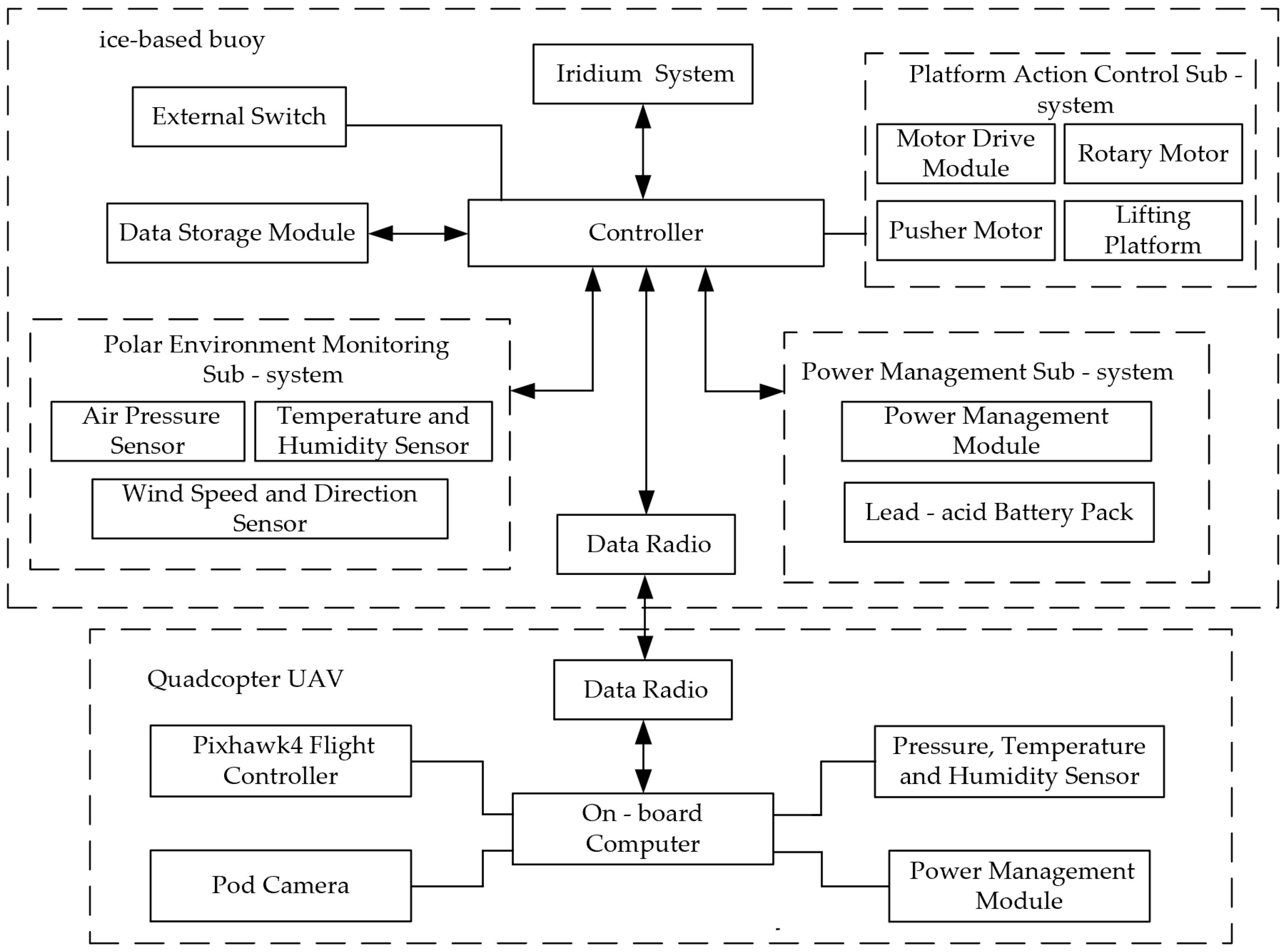
The observation system comprises an ice-based buoy and a quadcopter UAV, as illustrated in Figure 1. The buoy continuously monitors ambient environmental conditions, providing reliable decision-making criteria for determining UAV mission feasibility. A bidirectional communication link established via digital radio enables real-time data synchronization and command transmission between the buoy and UAV. Furthermore, the buoy functions as a power replenishment station, delivering essential electrical support to sustain prolonged UAV operations. The system architecture is detailed in the block diagram of Figure 2.

2.2. Ice-Based Buoy System

The ice-based buoy system consists of a baseplate, a connection panel, cabin, a hatch, a lifting platform, and a rotating arm, with mechanical parameters detailed in Table 1 and three-view diagrams shown in Figure 3. The baseplate, positioned at the system’s base, incorporates 18 aluminum alloy reinforcement ribs to enhance structural integrity. The connection panel, mounted atop the baseplate, facilitates subsystem integration through preconfigured power and control interfaces, improving system expandability and flexibility. Constructed from low-density 6061 aluminum alloy, the cabin houses a lifting platform equipped with a contact-based charging system. The hatch employs a tilt-sealed design to prevent snow ingress and foreign object intrusion, protecting internal equipment. The hatch connects to the rotating arm via a linear actuator, while the rotating arm interfaces with a hollow rotary platform driven by a rotary motor within the baseplate, ensuring robust hatch operation and reliable environmental sealing.
The ice-based buoy is equipped with an integrated system controller responsible for data acquisition and processing of the polar environmental monitoring subsystem, platform motion control subsystem, power management subsystem, data storage module, and communication system. Specifically, the polar environmental monitoring subsystem collects environmental data including temperature, humidity, atmospheric pressure, and wind speed/direction; the platform motion control subsystem ensures coordinated operation of buoy components; the power management subsystem optimizes energy usage to maintain continuous operation in extreme environments; the data storage module records and stores all acquired data for subsequent analysis; and the Iridium satellite communication system [18] transmits data to domestic monitoring platforms, enabling real-time monitoring and remote control. Equipment configurations are detailed in Table 2.

2.3. Quadcopter UAV System

The quadcopter UAV selected for this study exhibits the following performance specifications: a diagonal wheelbase of 600 mm, maximum flight endurance of 36 min, and maximum flight speed of 5 m·s−1. This platform enables comprehensive surveys of sea ice surface features within a 4 km operational radius of the buoy. Detailed parameters are provided in Table 3.
The quadcopter UAV system integrates critical components including the Pixhawk 4 flight controller [19], onboard computer, gimbal-mounted camera, digital radio, power management module, and environmental sensors (barometer, hygrometer, and thermometer). The onboard computer processes imagery captured by the gimbal-mounted camera, computes relative position data between the UAV and ground markers, and generates vision-based navigation commands transmitted to the flight control system. This enables stable flight during vision-guided landing operations. Additionally, the onboard computer facilitates command transmission and status reporting to the ice-based buoy via the digital radio link. Equipment configurations are detailed in Table 4.
Current polar sea-ice monitoring primarily relies on satellite remote sensing, fixed buoys, traditional unmanned aerial vehicle (UAV) platforms, and large-scale airborne observation systems. However, these approaches exhibit significant limitations: while satellite remote sensing offers the advantage of wide coverage, it exhibits low resolution in the marginal ice zone (MIZ) and high susceptibility to weather conditions, making high-precision real-time observation challenging. Fixed buoys only provide point-based environmental data and cannot perform areal image acquisition. Traditional UAVs are mostly dependent on manual operation, with deployment and operation constrained, making long-term autonomous mission execution difficult. Although airborne observation systems possess multi-source data capabilities, they are costly and complex to maintain, rendering them unsuitable for regular deployment. To address these issues, this paper proposes the UBCOS, which integrates centimeter-level RTK positioning, low-temperature contact-based charging, Iridium communication, and environmental sensing modules into the ice-based buoy, and is equipped with a UAV platform featuring autonomous control capabilities. This integration constructs a “buoy + UAV” cooperative observation framework, achieving fully unmanned sea-ice monitoring throughout the entire process in polar environments for the first time. The system is equipped with functions such as autonomous takeoff and landing, path planning, data acquisition and transmission, automatic charging, and mission cycling. In the 2024 Arctic field tests, it demonstrated excellent positioning accuracy, environmental adaptability, data integrity, and continuous operational capability. Compared with existing systems, UBCOS has achieved significant breakthroughs in terms of accuracy, frequency, intelligence level, and operational autonomy. It fills the gaps of traditional observation methods in local dynamic monitoring and autonomous operation, providing a feasible path for the construction of high-density, distributed polar observation networks in the future.

3. Cooperative Mode of UBCOS

The cooperative workflow between the ice-based buoy and quadcopter UAV encompasses three primary aspects: First, the buoy receives mission commands from the domestic monitoring platform and uploads them to the UAV to initiate monitoring operations; simultaneously, the buoy transmits UAV-acquired data back to domestic stations. Second, leveraging RTK positioning technology, the buoy provides RTCM correction data to the UAV, significantly enhancing positioning accuracy in polar environments. Finally, the buoy supplies electrical replenishment to the UAV through its contact-based charging system, ensuring sustained operational capability.

3.1. Hierarchical Structure

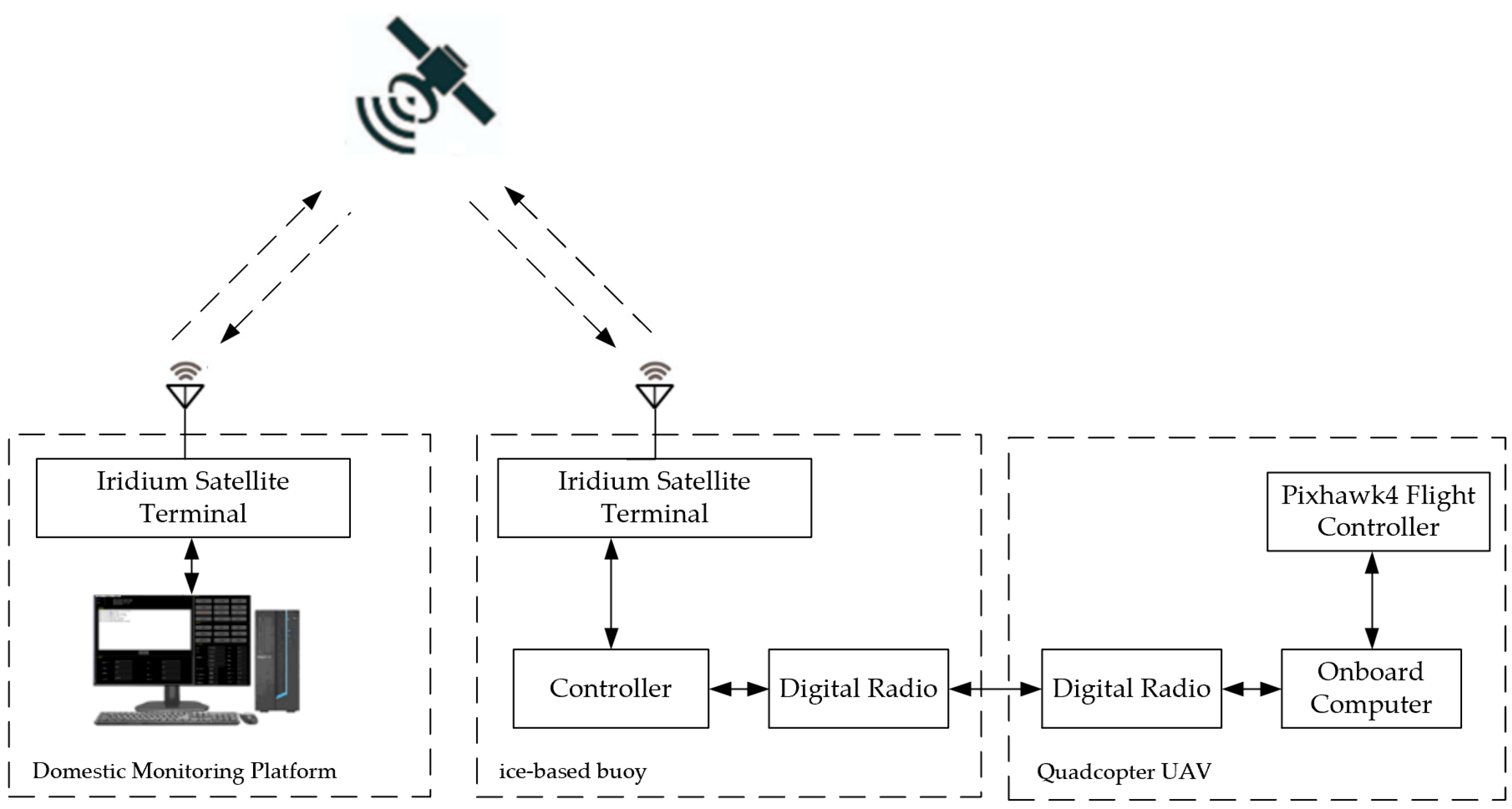
In this system, the domestic monitoring platform establishes a point-to-point communication link with the polar ice-based buoy via the Iridium 9523 terminal, enabling command upload and monitoring data downlink. Concurrently, the buoy forms a point-to-point link with the quadcopter UAV using digital radio, facilitating launch command dispatch, trajectory data upload, and real-time telemetry retrieval (including monitoring data and UAV status). The comprehensive communication architecture is illustrated in Figure 4. Through coordinated operation of the Iridium satellite system and digital radio, this framework achieves efficient, stable bidirectional communication among the domestic monitoring platform, ice-based buoy, and quadcopter UAV, fulfilling remote monitoring and control requirements in polar environments.
In the UBCOS, the Iridium communication module transmits data once per hour, striking a balance between low power consumption and data reliability. This design reduces energy usage, thereby enhancing the endurance of lead-acid battery packs in low-temperature environments and ensuring the stable operation of critical components such as the RTK base station. The chosen transmission interval corresponds to the slowly changing characteristics of polar environmental parameters, avoiding redundant data while maintaining the temporal continuity of key variables and UAV status information. Leveraging Iridium’s global coverage, the scheduled transmission of preprocessed data from local storage minimizes signal interference, thereby improving the reliability of remote data support for domestic platforms.
Related concepts have been explored in previous studies. Notably, Khudonogova and Muravyov proposed an energy-accuracy balancing scheme for Wireless Sensor Networks (WSNs) based on the Interval Fusion with Preference Aggregation (IF&PA) method. By integrating the SensAcc accuracy enhancement algorithm and the ActiveNode selection algorithm, their approach effectively reduces transmission frequency to conserve energy, while preserving measurement accuracy [20].

3.2. Cooperative Navigation Mode

In polar environments, traditional navigation methods are confronted with numerous challenges, such as harsh weather conditions, weak GPS signals, and even signal loss. The adoption of high-precision RTK positioning technology can significantly enhance the positioning accuracy of UAVs in complex scenarios, providing reliable guarantees for mission execution. RTK positioning technology transmits the measurement data or observation correction values from the reference receiver to the rover receiver via a data link. The data processing of the rover receiver includes ambiguity resolution of differential carrier phase data and estimation of position coordinates.
In this study, H-RTK F9P Base (Holybro Technology Co., Ltd., Wan Chai, Hong Kong SAR, China) is selected as the reference receiver, and H-RTK F9P Helical as the rover receiver [21], which are installed on the ice-based buoy and the quadcopter UAV, respectively. After the system is powered on, the H-RTK F9P Base first enters the survey-in process to initialize the base station position, and then outputs RTCM information. Once the controller detects the completion of the survey-in, it will send messages 1005, 1074, 1084, 1094, 1124, and 1230 in the RTCM3.3 protocol to the onboard computer of the quadcopter UAV via the digital radio at a frequency of 1 Hz. The onboard computer will receive these messages and transmit them to the UART2 port of the H-RTK F9P Helical. Upon starting to receive the input stream of RTCM correction messages, the H-RTK F9P Helical will quickly enter the RTK float mode. After resolving the ambiguity of the carrier phase, it will enter the RTK fixed mode, achieving centimeter-level positioning accuracy, which enables the quadcopter UAV to take off safely, complete the monitoring mission, and achieve precise landing. The structure block diagram of the RTK positioning system is shown in Figure 5.

3.3. Contact Charging System

Compared with the automatic battery replacement system, the contact-based charging system features a simpler structure, eliminating the need for additional mechanical structures and transmission devices, thus reducing equipment complexity and failure rates. Therefore, this study adopts a contact-based charging scheme, which mainly consists of a charger, a charging platform, and a charging structure for the quadcopter UAV. The power supply is derived from the lead-acid battery pack on the ice-based buoy, ensuring that the charging process is independent of external power sources and enhancing the system’s autonomy.
The SKYRC S100neo (SkyRC Technology Co., Ltd., Shenzhen, China) is selected as the charger, which can provide a charging power of 200 W and a charging current of 12 A under a DC power supply. In addition, this charger is equipped with a USB communication function [22]. Therefore, the controller can control the charging and power-off processes, and read information such as battery voltage, charging time, and charged capacity.
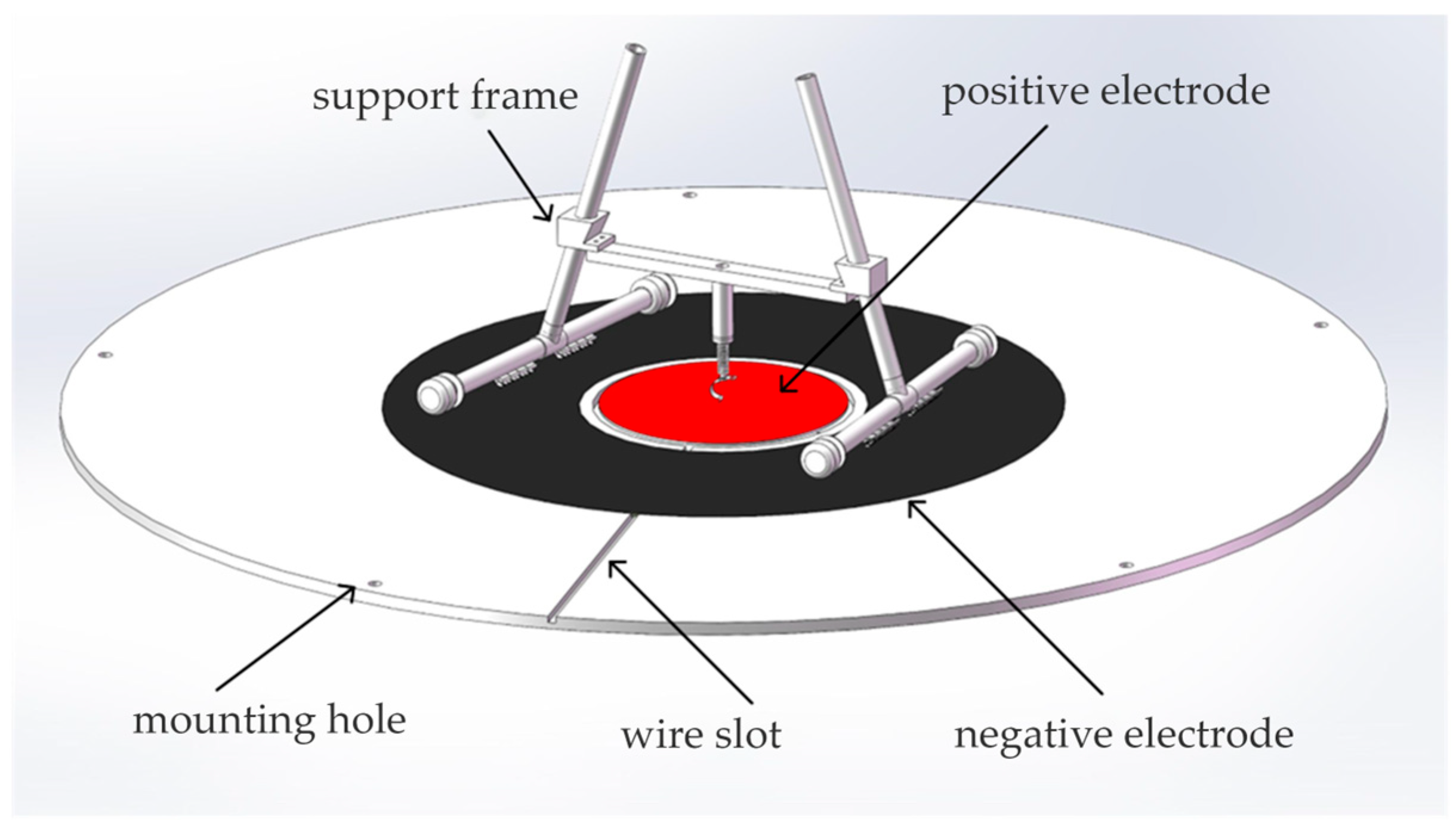
The design of the charging platform and the UAV charging structure aims to achieve efficient and reliable contact-based charging. The charging platform is constructed from a circular insulating bakelite board with a radius of 505 mm and a thickness of 10 mm. A cylindrical groove with a depth of 7 mm and a radius of 100 mm is set at the center, inside which a 2 mm thick copper plate is laid as the positive electrode. The negative electrode is arranged on the platform in a concentric circle pattern to ensure good electrical contact. To facilitate the UAV’s landing in the designated area and completion of charging, the positive electrode charging structure adopts a support frame design to ensure it is positioned at the center of the UAV. Meanwhile, it is equipped with a spring to enhance the electrode contact effect and reduce vibration. The negative electrodes are located at the bottom of the two landing gears. The three-dimensional structure diagrams of the charging platform and the UAV charging structure are shown in Figure 6.

3.4. Autonomous Operation Process

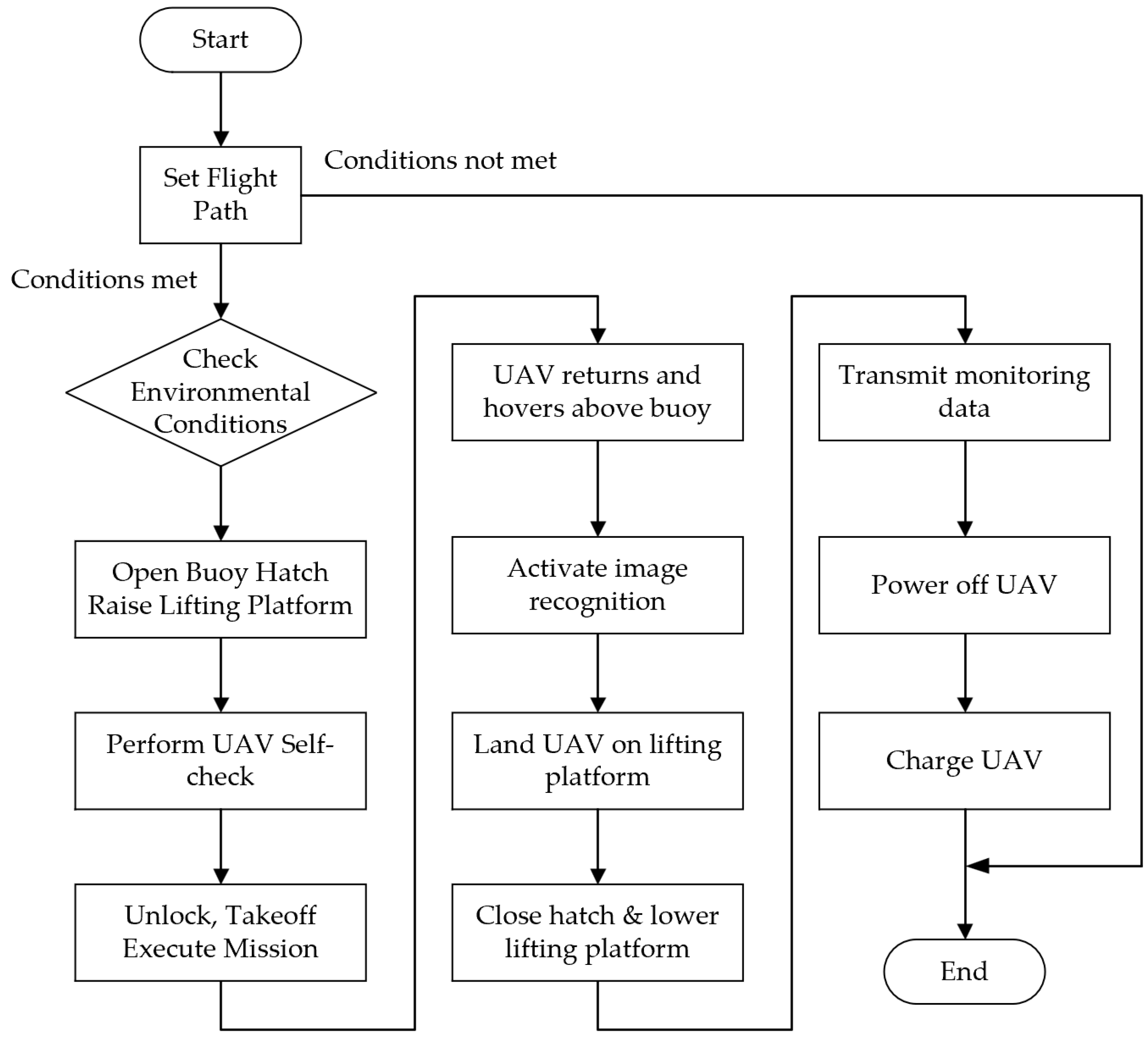
The mission execution of UBCOS mainly includes route setting, UAV mission execution, precise positioning and landing, data transmission, and automatic charging, with the specific process shown in Figure 7.
First, domestic operators set the UAV’s route information on the monitoring platform, including key parameters such as flight path, cruise speed, and pod pitch angle. After the setting is completed, operators upload the route information to the ice-based buoy via the Iridium communication system. Upon receiving the route information, the ice-based buoy performs integrity and validity verification to ensure the route information is correct. After verification, the information is stored in a local SD card, and the route is uploaded and mission preparations are initiated when environmental conditions meet the UAV’s flight requirements.
As the core of ground support for the UAV, the highly automated operation process of the ice-based buoy system must be fully adapted to the harsh Arctic environment with extreme low temperatures, strong winds, and snow cover. Through mechanical linkage and multi-technology integrated sensing capabilities, it enables safe takeoff and precise recovery of the UAV without manual intervention. This process is triggered by remote commands and short-range signals, with collaborative actions of subsystems as the core. The triggering mechanisms for system operation are divided into two types: one is receiving UAV takeoff commands sent by the domestic monitoring platform via the Iridium communication system, which contain key parameters such as preset routes and mission duration, and initiating the process after parsing by the STM32F103ZET6 controller; the other is when the UAV completes the monitoring mission or its battery level is below the threshold, it sends a homing approach signal to the buoy via UWB (Ultra-Wideband) short-range sensing technology, and the signal receiving module built into the buoy captures the UAV’s position in real time to trigger the receiving process.
After receiving the trigger signal, the system first enters the self-inspection and zeroing phase. The controller drives the top cover motor to start, synchronously calling position sensors (such as rotary encoders) of subsystems including the rotating arm and lifting platform to detect whether each component is in the initial position, specifically: whether the rotating arm is returned to the 0° reference position, whether the lifting platform is lowered to the bottom of the cabin, and whether the hatch is fully closed. If any subsystem deviates from the initial position (e.g., the lifting platform is stuck due to low temperature), the controller immediately initiates a reset procedure: driving the rotating arm to return to position via the D57M31 rotary motor, and the linear actuator motor (150 mm/s-1000 N) drives the lifting platform to reset until all position sensors feed back “in-place signals”; if all subsystems are in the initial state, zeroing is completed directly, and a “zeroing ready” command is sent to the UAV or cloud platform via the digital radio. The linear actuator’s parameters “150 mm/s-1000 N” mean it can move at a maximum speed of 150 mm per second and exert a maximum thrust of 1000 Newtons, enabling efficient and reliable operation of components like the hatch and lifting platform in the ice-based buoy system under polar conditions.
After zeroing, the system enters the equipment deployment phase. The linear actuator first acts to lift the top cover 50 mm upward from the sealed state, disengaging the locking structure with the cabin; subsequently, the D57M31 rotary motor drives the rotating arm to rotate clockwise, driving the top cover to rotate synchronously to 180°, completely exposing the lifting platform area; then, the lifting platform motor starts to raise the platform from inside the cabin to a height of 1.1 m (this height is optimized through polar tests to avoid collisions between the UAV and the buoy structure during takeoff and landing), and the contact-based charging electrodes on the platform are in a standby state.
Next, the buoy will detect current environmental parameters in real time, including wind speed, temperature and humidity, and positioning information. If the detected environmental information does not meet the flight requirements, the mission will be automatically aborted; if it meets the flight requirements, the buoy control system will be activated to open the hatch and lift the lifting platform to the preset height. At this time, the UAV will perform self-inspection to ensure all systems are operating normally. After successful self-inspection, the UAV will take off automatically and start executing the mission according to the set route information.
When the UAV confirms it is at a suitable position above the buoy through RTK positioning and image recognition, it performs takeoff or landing actions. For the takeoff process, after the UAV ascends, it feeds back a “takeoff completed” signal via the digital radio, and the controller then drives the lifting platform to lower to the initial position; for the recovery process, after the UAV lands precisely, the buoy detects the electrode contact signal, confirms the UAV is stable, and then initiates the platform lowering procedure.
Finally, the system enters the reset and storage phase. The rotary motor drives the rotating arm to rotate 180° counterclockwise, returning the top cover to the 0° position; the linear actuator contracts to press the top cover down to the initial state of close fit with the cabin, blocking the intrusion of wind and snow through the tilt-sealed design. At this point, the entire operation process is closed-loop, and the buoy returns to a low-power standby state, waiting for the next mission trigger.
After completing the monitoring mission, the UAV flies above the buoy, triggering the image recognition program. The mounted pod camera starts to identify the feature markers on the buoy, and combined with RTK positioning, ensures the UAV lands precisely. Finally, when the buoy detects that the UAV has successfully landed and stabilized, the hatch closes. Meanwhile, the UAV’s aerial survey data is transmitted to the buoy via the digital radio. The buoy transmits the data to domestic servers through the Iridium communication system, ensuring real-time data transmission and storage. After data transmission, the UAV automatically powers off and starts charging. After charging is completed, the mission ends, and the buoy enters a standby state, ready for the next mission.

4. Arctic Field Validation

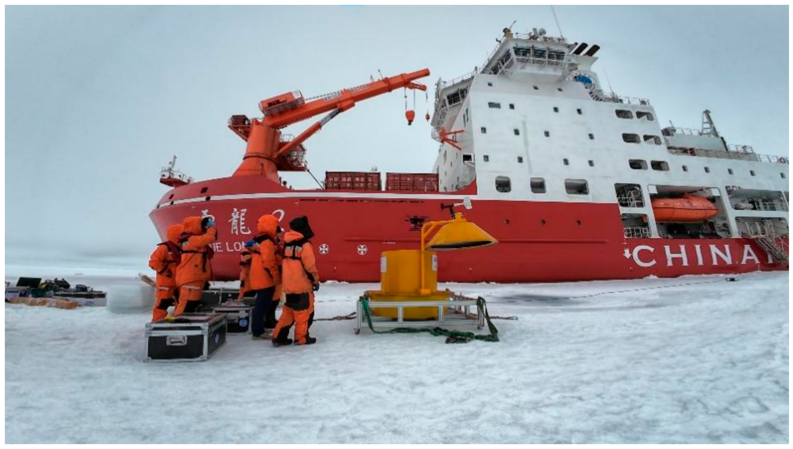
During the 14th Chinese National Arctic Research Expedition in 2024, the observation system was successfully deployed at 86.690510° N, 142.058423° W (Figure 8). Post-deployment, all critical subsystems of the ice-based buoy—including environmental monitoring, satellite communication, RTK positioning, and contact-based charging—operated nominally.
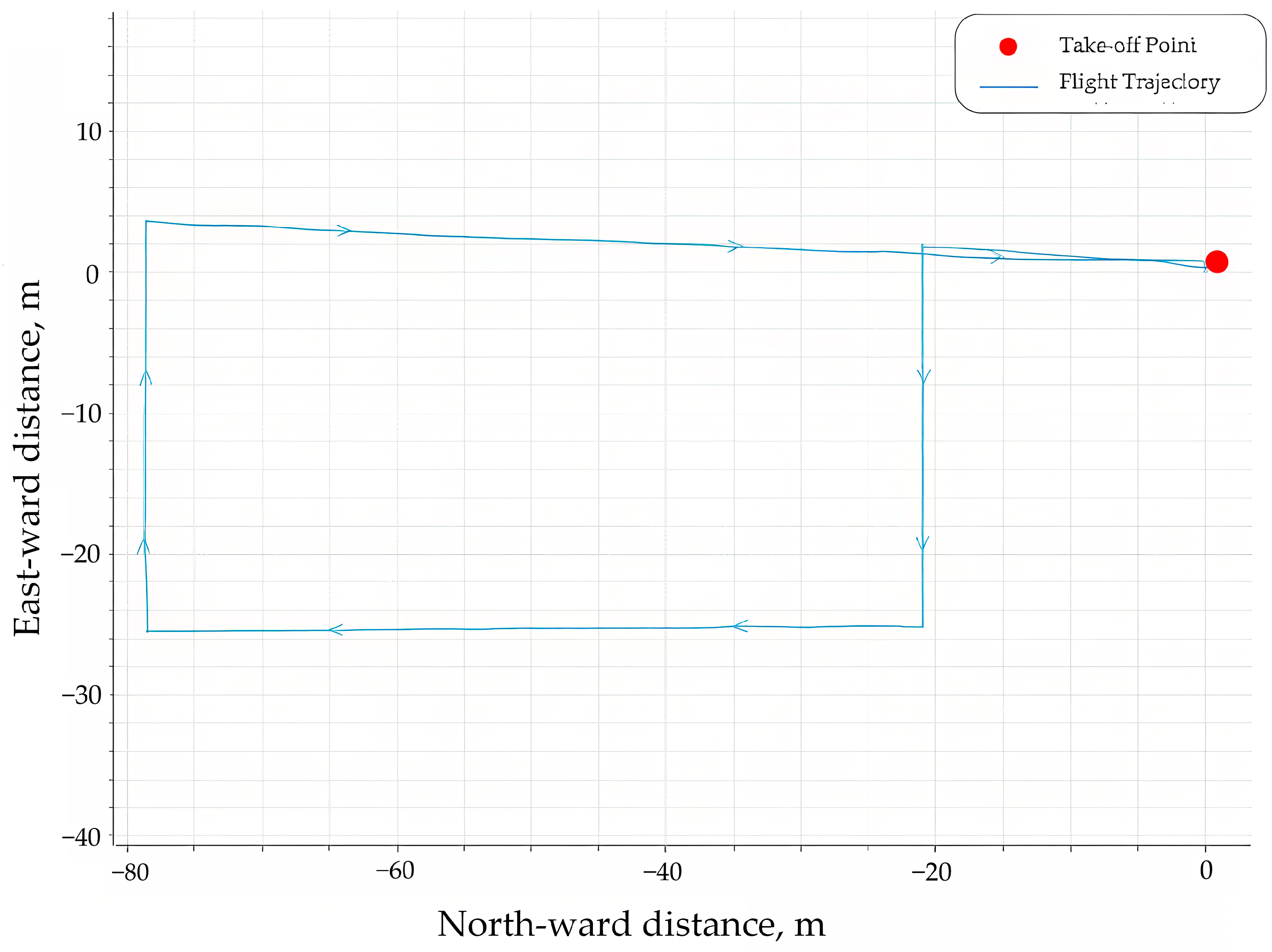
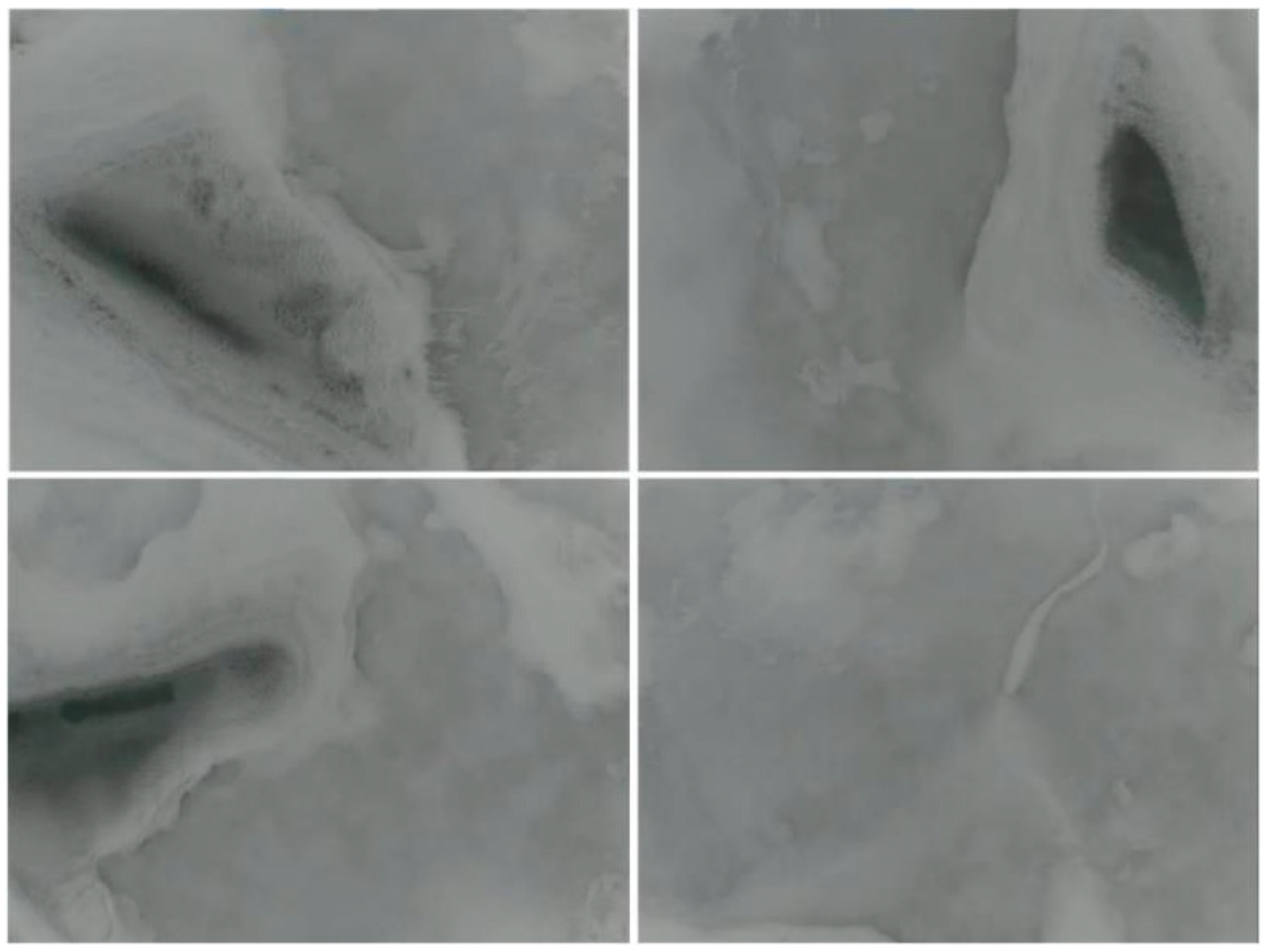
The ambient temperature was −1.1 °C, and the wind speed was 5.3 m/s, which meets the UAV’s flight requirement under the condition. In the experiment, the UAV executes the route mission at a maximum flight altitude of 60 m and a cruising speed of 3 m·s−1, and its flight trajectory is shown in Figure 9. During the mission execution, the UAV takes images of the ice surface through the mounted pod camera, and acquires image data including melt ponds, ice surface features, and other ice characteristics. Some of the shooting results are shown in Figure 10. In the sea-ice monitoring of the UBCOS, automated extraction and analysis of features such as melt pond distribution, ice surface roughness, and dynamic changes in the marginal ice zone captured by UAVs are achieved through algorithms. The system processes high-resolution ice surface images to accurately segment melt pond and ice surface areas, extracts edge features related to ice surface roughness, and obtains quantitative parameters such as melt pond coverage and roughness index through quantitative analysis. These parameters are spatially calibrated by combining with RTK positioning. The analysis results are adapted to the data transmission rhythm and regularly transmitted back via the Iridium system, providing quantitative support for sea-ice dynamic research. A similar approach can be found in the method proposed by Muravyov and Nguyen, who employed interval fusion with preference aggregation to improve accuracy in image feature extraction [23].
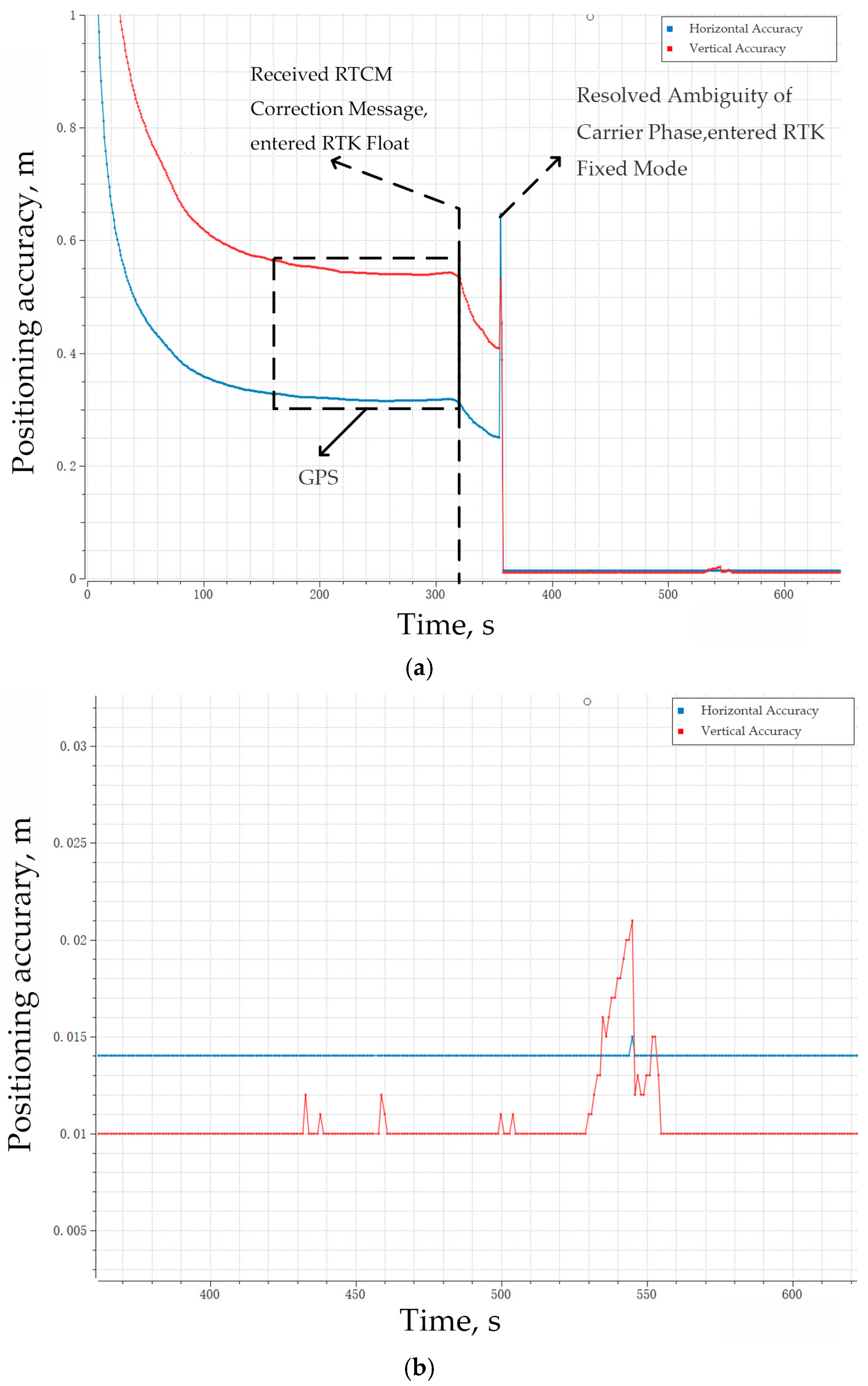
The UAV successfully completed the flight mission and achieved precise landing via RTK positioning technology. Test results demonstrated horizontal positioning accuracy of 0.014 m and vertical accuracy within (0.01–0.02) m, fully compliant with system design requirements. By contrast, GPS positioning yielded horizontal accuracy of only 0.35 m and vertical accuracy of 0.55 m, as illustrated in Figure 11. The H-RTK F9P Base reference station mounted on the ice-based buoy establishes a high-precision geographic coordinate reference datum through position initialization. During the execution of flight missions by the UAV, the positioning coordinates from both RTK and GPS are recorded in real-time. Finally, the positioning errors of RTK and GPS in polar environments are quantified, thereby clearly presenting the deviation differences between the two positioning technologies in complex polar environments.
RTK quickly achieves stable high-precision positioning after receiving correction data, whereas GPS consistently exhibits significantly larger and more fluctuating errors. Furthermore, the results confirm that RTK maintains sustained centimeter-level accuracy during stable operation.
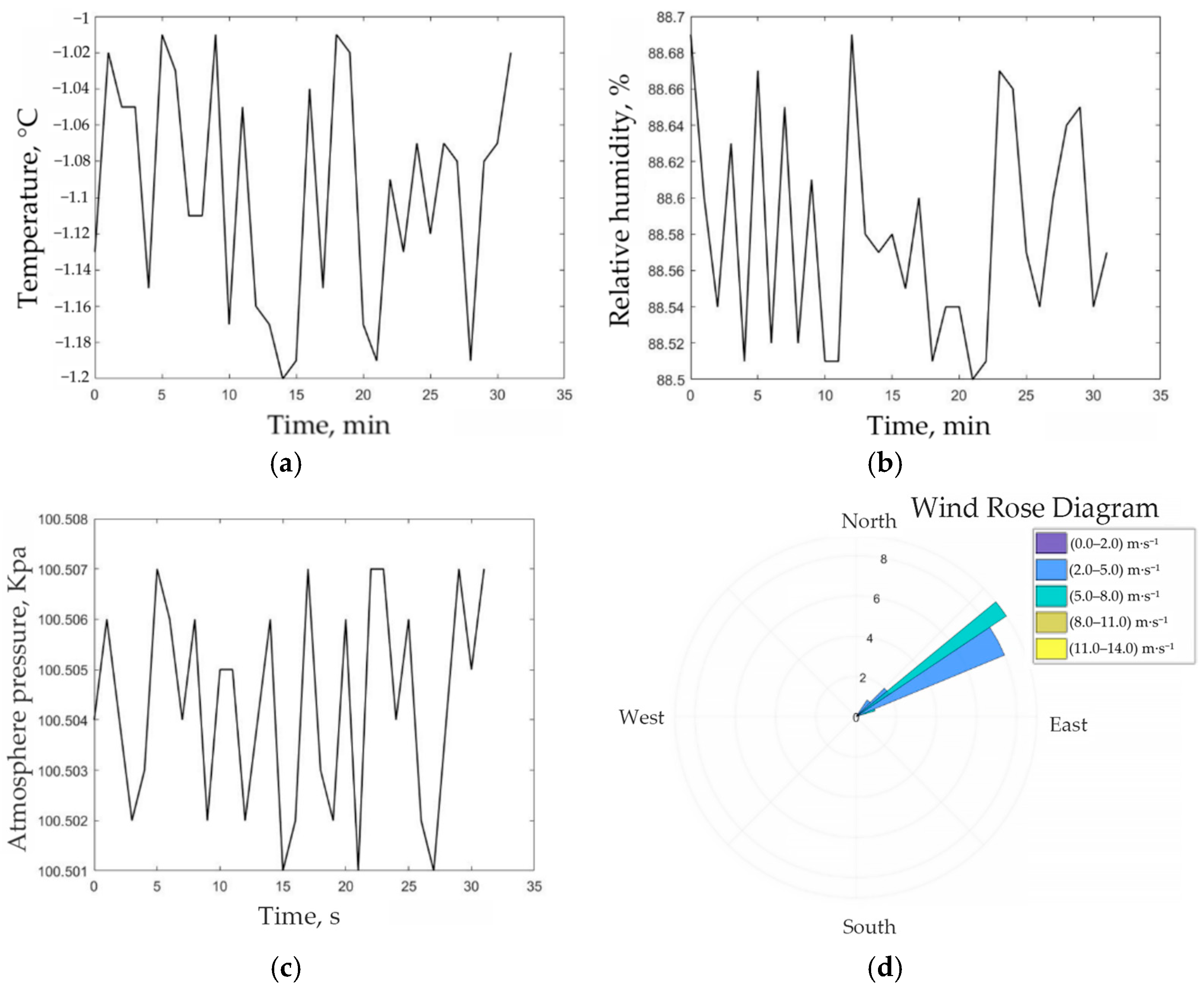
The environmental acquisition system of the ice-based buoy has continuously monitored the surrounding environmental data. It has successfully collected data on temperature, humidity, atmospheric pressure, wind speed, and wind direction, as shown in Figure 12.
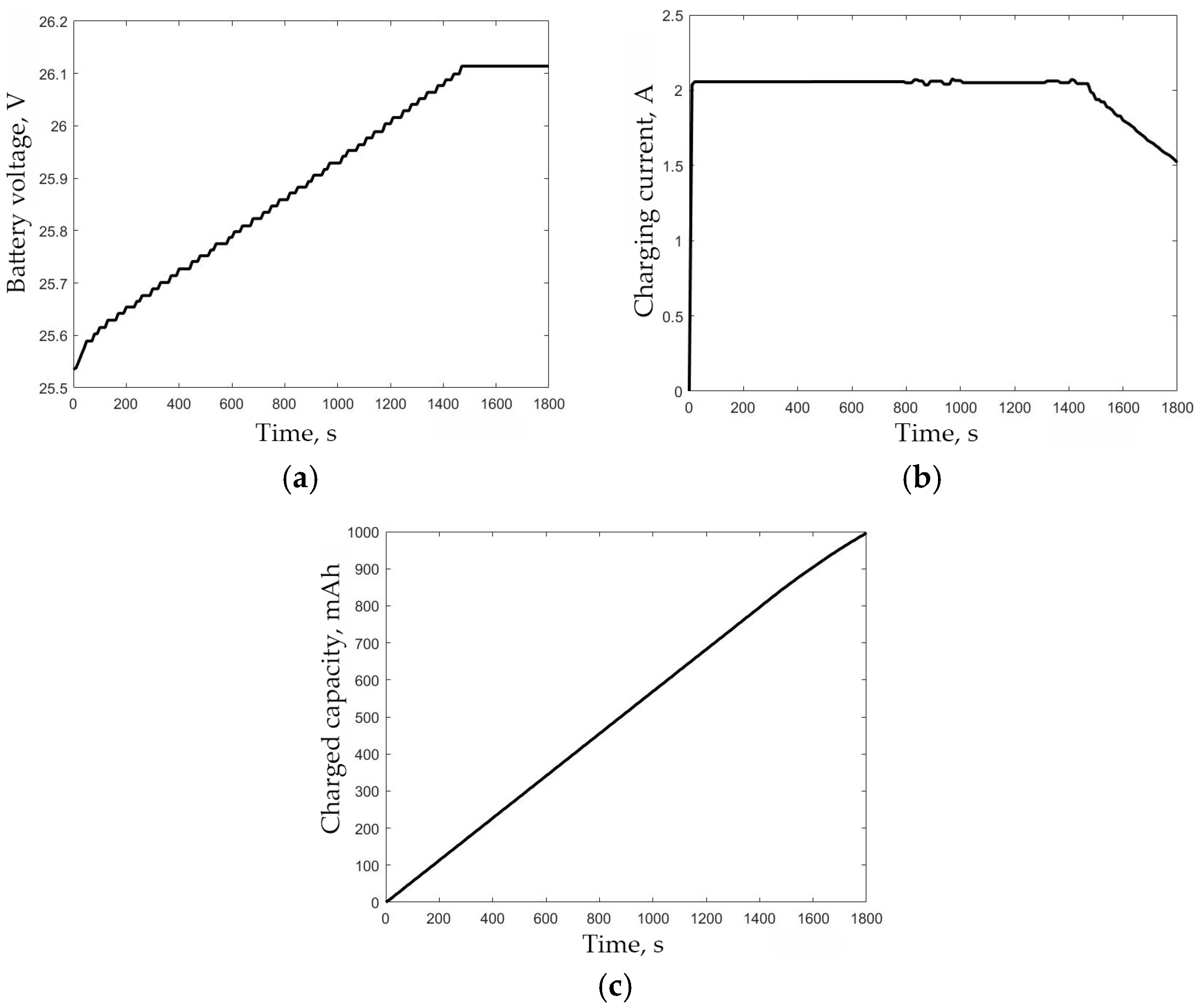
For the charging test, the initial voltage of the battery of the quadcopter UAV is 25.535 V, the charging current is 2 A, and the charging termination voltage is 26.1 V. The test lasted for 30 min, and the changes in battery voltage, charging current, and charged capacity during this period are shown in Figure 13.

5. Conclusions

UBCOS underwent an on-site test during China’s 14th Arctic Scientific Expedition in 2024. The system successfully executed the fully autonomous operation cycle of quadcopter UAVs, achieving centimeter-level landing precision (0.014 m horizontal accuracy) through integrated RTK positioning and image recognition. The contact-based charging system reliably replenished UAV power within 30 min at −1.1 °C across multiple orientations, sustaining long-term operations without human intervention. Field validation confirmed expected performance in both monitoring tasks (melt pond distribution, ice surface roughness mapping) and data collection (100% transmission integrity), demonstrating practicality and reliability for polar sea ice monitoring. These outcomes establish UBCOS as a robust solution for enhancing spatiotemporal resolution in sea ice dynamics observation, with significant potential for advancing climate models and Arctic navigation safety.
This study develops the UAV and Ice-based buoy cross-domain observation system (UBCOS), which innovatively integrates centimeter-level RTK positioning, low-temperature contact-based charging, Iridium communication, and autonomous control into a “buoy-UAV” cooperative framework. It achieves the first fully unmanned closed-loop polar sea ice monitoring cycle, overcoming limitations of traditional methods such as satellite remote sensing’s low precision in marginal ice zones (MIZ), fixed buoys’ point-based data constraints, and manual UAV operations’ endurance restrictions. UBCOS realizes high-precision positioning via RTK under weak polar GPS signals, ensures reliable low-temperature energy replenishment through a simplified contact charging system, and enables stable cross-domain data transmission via hierarchical communication. By bridging large-scale satellite monitoring and fine in situ measurements, it provides high-spatiotemporal-resolution data on sea ice dynamics, laying a technical foundation for distributed polar observation networks and advancing polar climate feedback research.
The UBCOS currently faces several limitations: its environmental adaptability is limited, as contact-based charging may suffer reduced conductivity under extreme cold, and the current wind resistance design cannot handle sudden Arctic gusts, affecting UAV stability during takeoff and landing. The UAV’s endurance and monitoring range are constrained by battery capacity, making it difficult to achieve continuous monitoring over large marginal ice zones. Additionally, although the Iridium system supports remote data transmission, its limited bandwidth leads to delays in real-time transmission of high-definition images. Future improvements can focus on enhancing low-temperature performance by using cold-resistant electrode materials, heating aids, and optimizing aerodynamic design to improve wind resistance; improving endurance through high-capacity low-temperature batteries or solar-assisted charging to achieve over 50 min of flight time; and establishing a communication redundancy mechanism that combines short-range digital radios with the Iridium system to prioritize key data and compress high-definition data for reduced transmission delay. These enhancements will strengthen UBCOS’s environmental resilience and expand its capabilities for long-term polar observation.

Author Contributions

Conceptualization, T.W. and S.Z.; methodology, Y.L.; software, T.W.; validation, Y.D.; formal analysis, L.K.; investigation, G.Z.; resources, G.Z.; data curation, Y.L.; writing—original draft preparation, T.W. and L.K.; writing—review and editing, G.Z. and L.K.; visualization, T.W.; supervision, Y.D.; project administration, Y.D.; funding acquisition, G.Z. All authors have read and agreed to the published version of the manuscript.

Funding

This research was funded by the National Natural Science Foundation of China, grant number 42306260, U23A20649, 62503353, the Shanghai Frontiers Science Center of Polar Science (SCOPS), grant number SOO2025-04, the Shanxi Province Water Conservancy Science and Technology R&D Service Project, grant number 2025GM22.

Data Availability Statement

The data that support the findings of this study are available from the corresponding authors upon reasonable request.

Conflicts of Interest

The authors declare no conflicts of interest.

References

  1. Cai, Q.; Wang, J.; Beletsky, D.; Overland, J.; Ikeda, M.; Wan, L. Accelerated decline of summer Arctic sea ice during 1850–2017 and the amplified Arctic warming during the recent decades. Environ. Res. Lett. 2021, 16, 034015. [Google Scholar] [CrossRef]
  2. Casey, J.A.; Howell, S.E.; Tivy, A.; Haas, C. Separability of sea ice types from wide swath C-and L-band synthetic aperture radar imagery acquired during the melt season. Remote Sens. Environ. 2016, 174, 314–328. [Google Scholar] [CrossRef]
  3. Dai, A.; Deng, J. Recent Eurasian winter cooling partly caused by internal multidecadal variability amplified by Arctic sea ice-air interactions. Clim. Dyn. 2022, 58, 3261–3277. [Google Scholar] [CrossRef]
  4. Wu, B.; Li, Z. Possible impacts of anomalous Arctic sea ice melting on summer atmosphere. Int. J. Climatol. 2022, 42, 1818–1827. [Google Scholar] [CrossRef]
  5. Li, X.M.; Sun, Y.; Zhang, Q. Extraction of sea ice cover by Sentinel-1 SAR based on support vector machine with unsupervised generation of training data. IEEE Trans. Geosci. Remote Sens. 2020, 59, 3040–3053. [Google Scholar] [CrossRef]
  6. Chen, J.; Kang, S.; Du, W.; Guo, J.; Xu, M.; Zhang, Y.; Chen, J. Perspectives on future sea ice and navigability in the Arctic. Cryosphere 2021, 15, 5473–5482. [Google Scholar] [CrossRef]
  7. Chen, J.; Kang, S.; You, Q.; Zhang, Y.; Du, W. Projected changes in sea ice and the navigability of the Arctic Passages under global warming of 2 °C and 3 °C. Anthropocene 2022, 40, 100349. [Google Scholar] [CrossRef]
  8. Lubin, D.; Massom, R. Polar Remote Sensing: Volume I: Atmosphere and Oceans; Springer: Berlin/Heidelberg, Germany, 2006. [Google Scholar]
  9. Shokr, M.; Sinha, N.K. Sea Ice: Physics and Remote Sensing; John Wiley & Sons: Hoboken, NJ, USA, 2023. [Google Scholar]
  10. Shokr, M.E.; Wilson, L.J.; Surdu-Miller, D.L. Effect of radar parameters on sea ice tonal and textural signatures using multi-frequency polarimetric SAR data. Oceanogr. Lit. Rev. 1996, 6, 634. [Google Scholar] [CrossRef]
  11. Beckers, J.F.; Renner, A.H.; Spreen, G.; Gerland, S.; Haas, C. Sea-ice surface roughness estimates from airborne laser scanner and laser altimeter observations in Fram Strait and north of Svalbard. Ann. Glaciol. 2015, 56, 235–244. [Google Scholar] [CrossRef]
  12. Gaffey, C.; Bhardwaj, A. Applications of unmanned aerial vehicles in cryosphere: Latest advances and prospects. Remote Sens. 2020, 12, 948. [Google Scholar] [CrossRef]
  13. Leira, F.S.; Johansen, T.A.; Fossen, T.I. A UAV ice tracking framework for autonomous sea ice management. In Proceedings of the 2017 International Conference on Unmanned Aircraft Systems (ICUAS), Miami, FL, USA, 13–16 June 2017; pp. 581–590. [Google Scholar]
  14. Wigmore, O.; Mark, B. Monitoring tropical debris-covered glacier dynamics from high-resolution unmanned aerial vehicle photogrammetry, Cordillera Blanca, Peru. Cryosphere 2017, 11, 2463–2480. [Google Scholar] [CrossRef]
  15. Eltoft, T.; Doulgeris, A.P.; Brekke, C.; Solbø, S.; Gerland, S.; Hanssen, A. Imaging sea ice structure by remote sensing sensors. In Proceedings of the 23rd International Conference on Port and Ocean Engineering under Arctic Conditions, Trondheim, Norway, 14–18 June 2015. [Google Scholar]
  16. Bhardwaj, A.; Sam, L.; Martín-Torres, F.J.; Kumar, R. UAVs as remote sensing platform in glaciology: Present applications and future prospects. Remote Sens. Environ. 2016, 175, 196–204. [Google Scholar] [CrossRef]
  17. Huang, X.; Liu, T.; Liu, H.; Wang, H. Overview of the application of unmanned aerial vehicles in the Arctic atmospheric observation system. In Proceedings of the 2022 WRC Symposium on Advanced Robotics and Automation (WRC SARA), Beijing, China, 20 August 2022; pp. 25–32. [Google Scholar]
  18. Ariya, P.A.; Jobson, B.T.; Sander, R.; Niki, H.; Harris, G.W.; Hopper, J.F.; Anlauf, K.G. Measurements of C2-C7 hydrocarbons during the Polar Sunrise Experiment 1994: Further evidence for halogen chemistry in the troposphere. J. Geophys. Res. Atmos. 1998, 103, 13169–13180. [Google Scholar] [CrossRef]
  19. Pixhawk. Pixhawk 4 Flight Controller. PX4 Autopilot. Available online: https://docs.px4.io/main/en/flight_controller/pixhawk4.html (accessed on 17 August 2025).
  20. Khudonogova, L.I.; Muravyov, S.V. Interval data fusion with preference aggregation for balancing measurement accuracy and energy consumption in WSN. Wirel. Pers. Commun. 2021, 118, 2399–2421. [Google Scholar] [CrossRef]
  21. Holybro. H-RTK F9P User Manual. Available online: https://holybro.com/ (accessed on 17 August 2025).
  22. SKYRC. S100neo User Manual. Available online: https://www.skyrc.com/s100neo?search=s100neo (accessed on 17 August 2025).
  23. Muravyov, S.V.; Nguyen, D.C. Method of interval fusion with preference aggregation in brightness thresholds selection for automatic weld surface defects recognition. Measurement 2024, 236, 114969. [Google Scholar] [CrossRef]
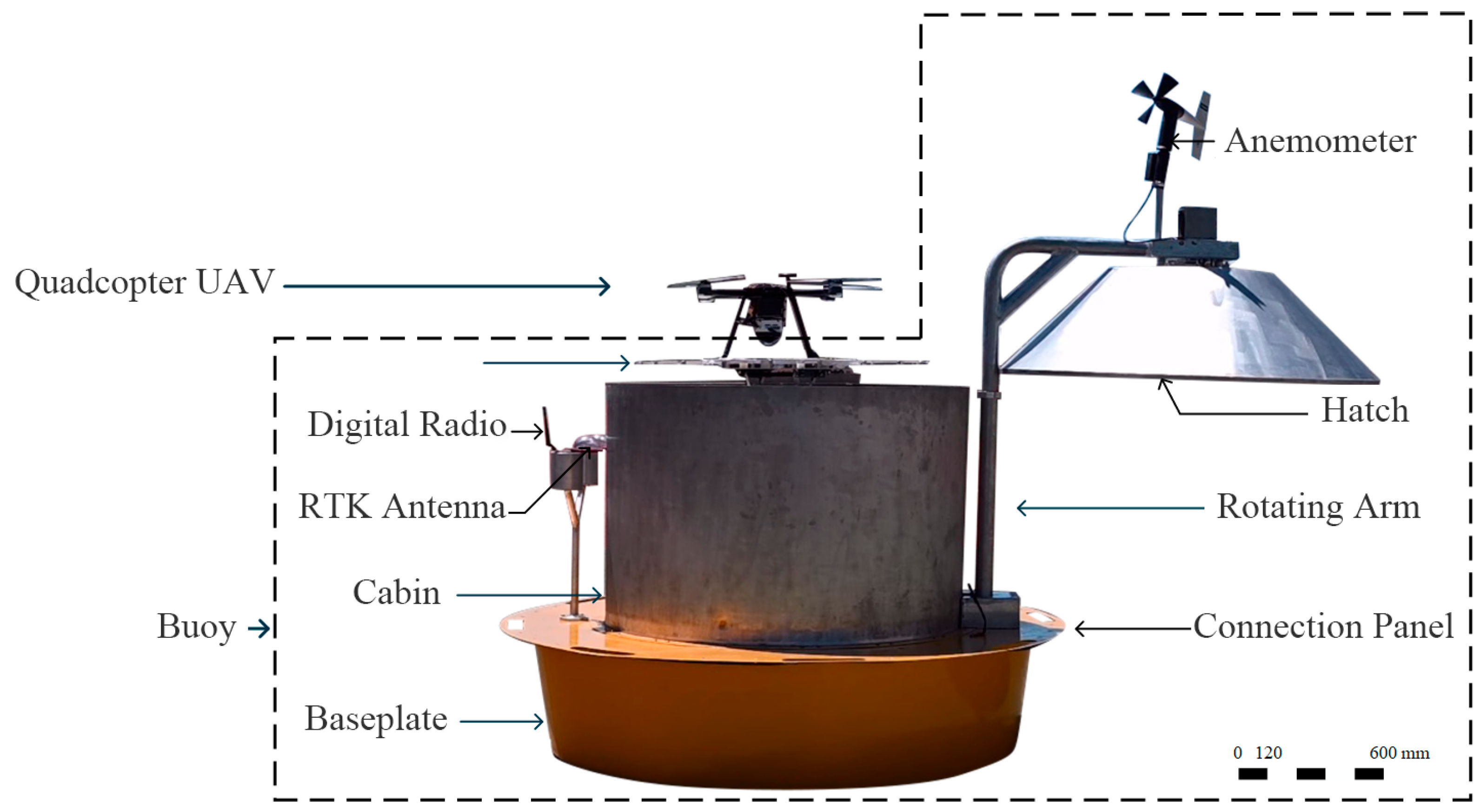
Figure 1. Schematic view of the UBCOS.
Jmse 13 01701 g001
Figure 2. System block diagram of the Observation System.
Jmse 13 01701 g002
Figure 3. The three views of ice buoy. (a) Front View, (b) Side View, (c) Top View.
Jmse 13 01701 g003
Figure 4. Communication Network Architecture of the Observation System.
Jmse 13 01701 g004
Figure 5. Structure block diagram of RTK positioning system.
Jmse 13 01701 g005
Figure 6. The three-dimensional models of charging platform of UAV.
Jmse 13 01701 g006
Figure 7. Autonomous Operation Flowchart of UBCOS.
Jmse 13 01701 g007
Figure 8. The Arctic Field of UBCOS during 14th Chinese National Arctic Research Expedition.
Jmse 13 01701 g008
Figure 9. Two-dimensional representation of the UAV flight trajectory in the local North-East-Down (NED) coordinate system.
Jmse 13 01701 g009
Figure 10. Typical images of the ice region captured by the UAV, including melt ponds and ice surface features.
Jmse 13 01701 g010
Figure 11. The horizontal position accuracy (blue) and vertical position accuracy (red) are compared between RTK and GPS. (a) The accuracy variation over the full time period (0–600 s), (b) An enlarged view of the accuracy variation during the (400–600) s time period.
Jmse 13 01701 g011
Figure 12. Environmental sensor data. (a) Temperature, (b) Relative humidity, (c) Atmosphere pressure, (d) Wind Rose Diagram.
Jmse 13 01701 g012
Figure 13. Charging test. (a) Battery voltage variation over time, (b) Charging current variation over time, (c) Charged capacity variation over time.
Jmse 13 01701 g013
Table 1. Mechanical parameters of the ice buoy.
ComponentHeight (mm)Dimension (mm)MaterialMass (kg)
Baseplate4001500CP-Ti alloy59.080
Connection panel319006061 Al alloy22.096
Cabin80012006061 Al alloy26.155
Lifting platform165–1105300 × 400Alumina13.900
Hatch20012056061 Al alloy14.112
Rotating arm1050606061 Al alloy13.082
Table 2. The ice-based buoy configuration.
DeviceModel/Specification
ControllerSTM32F103ZET6 (STMicroelectronics, Geneva, Switzerland)
Barometric SensorVaisala PTB210 (Vaisala, Vantaa, Finland)
Thermo-HygrometerVaisala HMP 155 (Vaisala, Vantaa, Finland)
AnemometerXFY3-1 (Micoyi (Beijing) Technology Co., Ltd., Beijing, China)
Rotary MotorD57M31 (Leadshine Intelligent Control Co., Ltd., Shenzhen, China)
Linear Actuator150 mm/s-1000 N (100 kg) (Leadshine Intelligent Control Co., Ltd., Shenzhen, China)
RTK Reference ReceiverHolybro H-RTK F9P Base (Holybro Technology Co., Ltd., Shenzhen, China)
Iridium Satellite SystemIridium 9523 (Iridium Communications Inc., McLean, VA, USA)
Digital RadioHolybro SiK Telemetry Radio V3 (Holybro Technology Co., Ltd., Shenzhen, China)
Data Storage ModuleOpenlog 64G (SparkFun Electronics, Niwot, CO, USA)
Lead-Acid Battery Pack2 × 12 V 250 Ah (Santak Electronics (Shenzhen) Co., Ltd., Shenzhen, China)
Table 3. The parameters of quadcopter UAV.
ParameterValue
Mass3.2 kg
Diagonal wheelbase600 mm
Max takeoff weight4.0 kg
Payload capacity0.8 kg
Endurance36 min
Wind resistanceLevel 6–7
Power sourceHigh-voltage Li-ion battery
Operating voltage23.1 V
Max flight altitude100 m
Table 4. Configuration of quadcopter UAV.
DeviceModel
Flight controllerPixhawk 4(Holybro Technology Co., Ltd., Wan Chai, Hong Kong SAR, China)
Onboard computerNVIDIA Jetson Orin NX (NVIDIA Corporation, Santa Clara, CA, USA)
Gimbal-mounted cameraPinling Q10F (Guangdong Pinling Technology Co., Ltd., Foshan, China)
RTK rover receiverHolybro H-RTK F9P Helica (Holybro Technology Co., Ltd., Shenzhen, China)
Digital radioHolybro SiK Telemetry Radio V3 (Holybro Technology Co., Ltd., Shenzhen, China)
Baro-thermo-hygrometerBOSCH BME280 (Bosch Sensortec GmbH, Reutlingen, Baden-Württemberg, Germany)
Disclaimer/Publisher’s Note: The statements, opinions and data contained in all publications are solely those of the individual author(s) and contributor(s) and not of MDPI and/or the editor(s). MDPI and/or the editor(s) disclaim responsibility for any injury to people or property resulting from any ideas, methods, instructions or products referred to in the content.