Article

Predefined-Time Formation Tracking Control for Underactuated AUVs with Input Saturation and Output Constraints

1
College of Intelligent Systems Science and Engineering, Harbin Engineering University, Harbin 150001, China
2
Southampton Ocean Engineering Joint Institute at HEU, Harbin Engineering University, Harbin 150001, China
*
Author to whom correspondence should be addressed.
J. Mar. Sci. Eng. 2025, 13(9), 1607; https://doi.org/10.3390/jmse13091607
Submission received: 3 July 2025 / Revised: 11 August 2025 / Accepted: 20 August 2025 / Published: 22 August 2025
(This article belongs to the Special Issue Design and Application of Underwater Vehicles)

Abstract

In this work, a predefined-time formation output constraint control method is proposed for underactuated AUVs with input saturation. First, a coordinate transformation method is utilized to convert the underactuated AUV system into a fully actuated system form. A universal time-varying asymmetric barrier function is constructed to convert the system to an unconstrained form and construct the formation tracking error. Then, a predefined-time formation output constraint control law is designed based on the active disturbance rejection control framework and predefined-time control method, which can achieve the control objective without relying on the precise mathematical model of the system. In addition, to address the input saturation issue, a novel predefined-time auxiliary dynamic system (ADS) is proposed. The proposed method with ADS can ensure that the multi-AUV system with input saturation can complete the formation output constraint tracking control task within a predefined time. Finally, a simulation is designed to verify the effectiveness of the proposed method.

1. Introduction

Autonomous underwater vehicles (AUVs) are a typical type of marine device that is widely utilized to accomplish all kinds of underwater missions. In the case of more complex tasks with larger working areas, it is essential for multiple AUVs to collaborate. In this background, formation control for AUVs has gained significant research attention [1,2].
In most scenarios, underactuated AUVs are more widely applied than fully actuated AUVs [3,4,5,6,7]. However, due to the uncontrollable state included in the motion model of underactuated AUV, it cannot be directly controlled with a traditional state feedback control technique. To address the control issue for underactuated AUV formation, the line-of-sight (LOS) technique offers an efficient solution [8,9]. The core principle of this approach consists in designing a kinematic-based guidance law, and then set it as a desired velocity to be tracked by the kinetic model. However, when designing distributed control methods for the AUV formation system, it is difficult to apply LOS method design distributed guidance laws for the formation system, which undoubtedly increases the difficulty of control system design.
In practice, in order to achieve the desired maneuverability of the AUV, the formation error must converge in finite time [10,11,12,13]. A large number of existing results have been reported on this issue. However, the upper bound of the formation error convergence time obtained through such methods often depends on the initial value of the system error. To deal this issue, a fixed-time formation control method for AUVs was proposed. The feature of this method is that the convergence time of the formation error is independent of the initial value of the system error, and the upper bound of the convergence time of the formation error can be changed by the user adjusting the control law parameters [14,15]. However, from an engineering application perspective, it is more convenient for users to set the maximum settling time. Accordingly, the concept named predefined time control has been proposed [16,17]. It integrates the advantages of fixed-time control with benefits of freely setting maximum tracking error convergence time. Moreover, it is worth mentioning that, different from theoretical research, due to the constraints of mechanical structure and propeller power in actual AUV systems, the phenomenon of actuator saturation needs to be considered [18,19,20,21]. The limited control inputs can often affect the achievement of predefined-time formation control for AUVs. How to address the predefined-time control issue of the AUV formation while considering actuator saturation prompted us to begin designing and organizing the content of this work.
The performance of the system is also affected by environmental disturbances and modeling uncertainties [22,23,24]. The most commonly used methods for addressing such issues are adaptive control methods based on neural networks and active disturbance rejection control (ADRC) methods. The key idea of the neural network-based adaptive control method is to approximate the unmodeled dynamics of the system based on the neural network, and then combine adaptive techniques to estimate the upper bound of environmental disturbances. In [25], an anti-swing tracking control strategy based on enhanced adaptive neural networks is proposed for offshore ship-mounted cranes. The enhanced adaptive neural network is utilized to address complex uncertainties, thus achieving high-performance control of the ship-mounted crane. In [26], an adaptive trajectory tracking control law based on neural networks is designed for marine surface vehicles. The neural network is utilized to approximate the optimal control law and unknown nonlinear dynamics, ultimately achieving optimized tracking control of the marine surface vehicles. However, it often makes theoretical analysis more conservative when introducing disturbance upper bound information to design the control law. In this case, the control input of the system may change more rapidly and with larger amplitude, which may increase the mechanical burden on the actuator. How to estimate the uncertainty of the system more accurately, reduce the operational burden on the actuator, and optimize system performance is a worthwhile topic for research. The ADRC technique can effectively address the above issues. The key components required in the ADRC design process are the extended state observer and the tracking differentiator. The extended state observer is often utilized to estimate the lumped uncertainty caused by environmental disturbances and unmodeled system dynamics. The convergence analysis of extended state observer can often be independent of the stability analysis of the system, so it can be easily combined with different kinds of control methods. The application of the tracking differentiator is more flexible and is often utilized within the framework of backstepping control to estimate the derivative of the virtual control law. With the introduction of the tracking differentiator, the phenomenon of “computational explosion” has been largely avoided. At present, the ADRC technique has been widely applied in the control law design of all kinds of unmanned systems. In [27], a active disturbance rejection trajectory tracking controller is designed for quadcopter unmanned aerial vehicles (UAVs). The control method is designed based on the backstepping technique, ultimately achieving high-performance control for UAVs subject to external disturbances and model uncertainties. In [28], an ADRC scheme is proposed for the electromagnetic docking mission for spacecraft. Under conditions with time-varying delays and fault signals, it can ensure high-precision control of spacecraft. However, based on the above investigation, the output constraint control of AUV formations based on the ADRC technique is still an insufficiently explored research area.
The safety control of multiple unmanned systems has also been a hot topic in recent years [29,30]. It is also important to note that output constraints caused by work environment limitations or communication scope need to be considered when designing formation control methods for AUV to ensure safe operation. In order to deal with the constraint control issue of nonlinear systems, the barrier Lyapunov function (BLF) is proposed and widely applied [31,32]. Inspired by the above, different kinds of BLF have also been proposed. The most typical are tan-type and log-type BLF, which are widely applicable [33,34,35,36,37]. However, this kind of method usually indirectly constrains the system state by constraining the system error, which will make the constraint boundary extremely conservative. In order to tackle this issue, in [38,39], an integral BLF was proposed. Then, to further deal with the asymmetric time-varying constraint control issue, a nonlinear state-dependent function (NSDF) is proposed [40,41]. The method applies the NSDF to convert the system to an unconstrained form, thus achieving constraint control for the nonlinear system. It should be noted that the aforementioned constraint control methods are generally applied to tackle the control issue when the upper and lower bounds of the constraints are greater than and less than zero, respectively, and are often employed to address the issue of designing constraint control methods for a single system. Based on the above observation, the problem of formation output constraint control for multiple AUVs has not been widely investigated and still deserves further research.
Inspired by the above discussion, we innovatively propose a predefined time formation output constraint control method for underactuated AUVs. This method is based on the ADRC technique and the backstepping control framework, and considers the actuator saturation phenomenonwhich may occur in practice. The main features and innovations can be summarized as follows:
  • In contrast to work [42,43,44], the formation control method for underactuated AUVs proposed in our work provides the user with the freedom to adjust the maximum convergence time of formation error. Furthermore, considering the effect of actuator saturation on the predefined time formation control of the AUV, a new auxiliary dynamic system (ADS) is constructed to ensure the system stability within the predefined time.
  • Different from the methods proposed in the work [45,46,47,48]. In this work, a universal time-varying asymmetric barrier function (UTABF) is introduced to achieve formation output constraint control of AUVs. The BLF can be applied to address more general dynamic constraint issues and can deal with both constrained and unconstrained cases without changing the control law.
  • In this work, the active disturbance rejection control (ADRC) framework is utilized to design the predefined-time output constraint control method for AUV formation. The method eliminates dependence on exact AUV modeling and provides stronger anti-disturbance abilities.
The rest of this paper is organized as follows. Formation tracking control for AUVs problem formulation and the motion model description of AUV are particularized in Section 2. In Section 3, the main results of this paper can be found, including the designed UTABF to address the issue of formation output constraint requirements, distributed predefined-time active disturbance rejection formation control law Design, and stability analysis. Simulation results are described to evaluate the control performance in Section 4. Finally, Section 5 contains the conclusion and future work.
Notation: R M represents the M-dimensional Euclidean space and R M × N denotes the set of M × N real matrices. · is the Euclidean norm. The symbol s i g g · is described as s i g g · = · g sign · with g is a positive constant and sign is the standard signum function, · is the absolute value symbol.

2. Problem Formulation

This work is developed based on the dynamic model of a five-degree-of-freedom AUV as shown in Figure 1. The characteristics of the AUV under consideration are comparable to the WL-2 type AUV, with a slender and streamlined shape [49]. In terms of actuator configuration, the AUV is equipped with a main thruster, a pair of vertical rudders, and a pair of horizontal rudders. The motion of the AUV is controlled by the propulsion system and rudder working together. The thruster provides propulsion, the vertical rudder controls yaw rotation, and the horizontal rudder controls pitching rotation. Due to the lack of thrusters in the vertical and horizontal directions, the AUV is underactuated and cannot dive vertically, move horizontally, or roll, and cannot complete dynamic positioning missions. When it is needed to change the depth and horizontal position, it is necessary to adjust the pitch angle or heading angle separately through the horizontal rudder or vertical rudder to adjust the depth or change the steering direction.
We consider a formation consisting of N AUVs. In this section, we describe the dynamics of underactuated AUVs. Furthermore, to address the underactuation problem, a coordinate transformation method is introduced.

2.1. AUV Dynamics and Assumptions

2.1.1. AUV Dynamics and Coordinate Transformation

The underactuated AUV dynamic is modeled as
η ˙ i = R i η i ν i M i ν ˙ i + C i ν i ν i + D i ν i ν i + g i η i = τ i + Δ i
where η i = x i , y i , z i , θ i , ψ i T represents the position and orientation of the ith AUV in the earth-fixed frame, ν i = u i , v i , w i , q i , r i T denotes the velocity in the body-fixed frame. R η i is the rotation matrix and M i = diag m i X u ˙ i , m i Y v ˙ i , m i Z w ˙ i , I y i M q ˙ i , I z i N r ˙ i is the inertia matrix. The Coriolis–centripetal matrix C i ν i is depicted as
C i ν i = 0 3 × 3 C 1 i v i C 2 i v i 0 2 × 2
with
C 1 i ν i = m i w i Z w ˙ i w i m i v i + Y v ˙ i v i 0 m i u i X u ˙ i u i m i u i + X u ˙ i u i 0
C 2 i ν i = m i w i + Z w ˙ i w i 0 m i u i X u ˙ i u i m i v i Y v ˙ i v i m i u i + X u ˙ i u i 0
The hydrodynamic damping matrix is denoted as D i ν i = diag { X u i + X | u | u i u i , Y v i + Y | v | v i v i , Z w i + Z | w | w i w i , M q i + M | q | q i q i , N r i + N | r | r i r i } . g i η i = 0 , 0 , 0 , 8.8 sin θ i , 0 T denotes the restoring forces and moments. The parameters in M i , C i ν i , and D i ν i will be given in the numerical simulation section of this paper. τ i = τ i , u , 0 , 0 , τ i , q , τ i , r T represents the input forces and moments. Δ i stands for the environmental disturbances. Please see [49] for more details about this dynamic model.
For practical applications, actuator mechanical constraints lead to control forces and moments described by
τ i , κ = sign τ i , c , κ τ κ , max , τ i , c , κ τ κ , max τ i , c , κ , τ i , c , κ < τ κ , max
where τ κ , max , κ = u , q , r , is the bound of τ i , κ , and τ i , c , κ is the command control signal.
The underactuated characteristics of AUVs motivate the introduction of the coordinate transformation as follows:
η ¯ i = x i + cos θ i cos ψ i , y i + cos θ i sin ψ i , z i sin θ i T
where > 0 is the length from virtual point to the mass centre of the ith AUV.
According to (1) and (3), we can obtain
η ¯ ˙ i = R 1 , i η i ν ¯ i + R 2 , i η i , ν i ν ¯ ˙ i = F i + M ¯ i 1 τ ¯ i
where ν ¯ i = u i , q i , r i T and τ ¯ i = τ i , u , τ i , q , τ i , r T . R 1 , i η i is the rotation matrix after the system has been transformed and M ¯ i = diag m 11 , i , m 44 , i , m 55 , i . R 2 , i η i , ν i and F i are nonlinear dynamics mentioned in [50].

2.1.2. Assumptions

To achieve output constraint formation tracking control of underactuated AUVs, we introduce the following assumptions.
Assumption 1.
The time derivative of F i is bounded, i.e., F ˙ i K 0 with K 0 > 0 .
Assumption 2.
The extended graph G contains a rooted spanning tree originating from the leader node.

2.2. Graph Theory

The interactive communication between individuals in the AUV formation can be described by a directed graph G = V , E , A , where V denotes the set of nodes and E denotes the set of edges. A = a i j R N × N represents the adjacency matrix of G , where a i j = 1 if node i can receive information from node j, otherwise a i j = 0 . We assume that the graph does not contain self-loops, i.e., a i i = 0 . Define the Laplacian matrix as L = l i j R N × N , where l i j = a i j i j and l i i = j = 1 , j i N a i j . L can be obtained by L = D A , where D = diag d 1 , d 2 , , d N denotes the degree matrix of G and d i = j = 1 N a i j . Define B = diag a 10 , a 20 , , a N 0 , where a i 0 = 1 if and only if the ith follower has a directed information flow from the virtual leader, and a i 0 = 0 otherwise. Then, we denote the matrix H = L + B .

2.3. Lemmas

The following lemmas are essential when designing the predefined-time formation output constraint control scheme.
Lemma 1.
If z i 0 i = 1 , 2 , , n and γ > 0 , then we have
i = 1 n z i γ i = 1 n z i γ , if 0 < γ < 1 i = 1 n z i γ n 1 γ i = 1 n z i γ , if γ > 1 .
Lemma 2.
Consider the system x ˙ = h t , x . If the Lyapunov function V satisfying
V ˙ π μ T c ϑ 1 V 1 μ 2 + ϑ 2 V 1 + μ 2
where ϑ 1 > 0 , ϑ 2 > 0 , T c > 0 , and 0 < μ < 1 . Then, the system achieves predefined-time stability.

3. Main Results

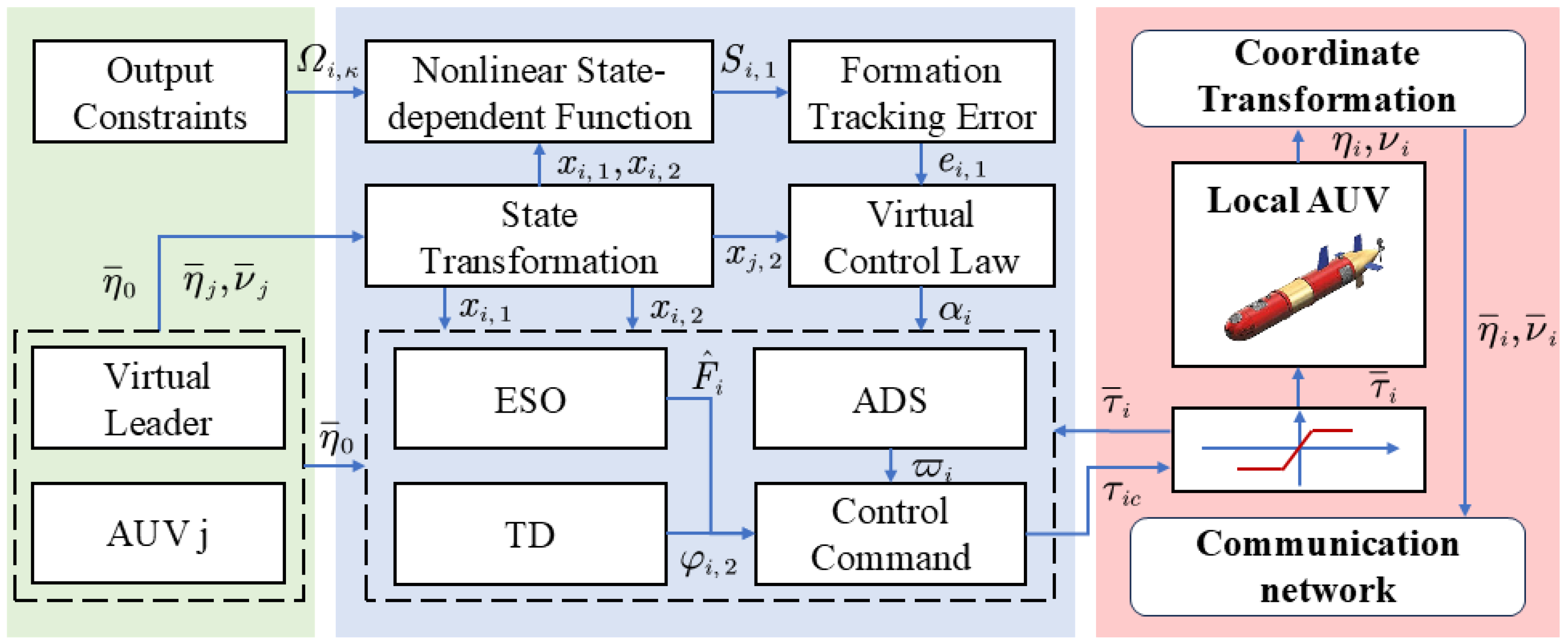
In this section, we design a UTABF to transform the constrained system (4) into an unconstrained system. Then, based on predefined-time control technique and ADRC framework, we design a distributed ADRC method for the AUV formation. In addition, when designing the control method, we also consider the effect of input saturation and design an predefined-time ADS to compensate for the control input. Finally, we prove that the formation tracking error of AUVs will converge within a predefined time. Figure 2 depicts the control framework.
In this control framework, we assume that the reference signal for formation tracking is generated by a virtual target. In practice, the reference signal can also be generated by path planning or obstacle avoidance algorithms. The focus of our work is on how to enable multi-AUV systems to track targets in formation based on reference signals. The position and velocity information of each AUV is assumed to be available. The position and velocity information is measured by sensors and then transmitted to neighboring AUVs via the communication topology. In particular, the position information is converted via UTABF and then utilized to construct unconstrained formation error. The velocity information is provided as input to a fixed-time extended state observer (FxESO) to estimate the lumped uncertainty of the system. Then, combining the backstepping technique, we design the formation output constraint control law for the AUV. Based on unconstrained formation error, we designed a virtual control law to provide the desired speed for the AUV. Subsequently, a formation output constraint control law is designed for the AUV to ensure the actual speed of the AUV tracks the virtual control law, ultimately achieving formation tracking of the target by the AUV. To avoid complex calculations caused by taking the derivative of the virtual control law, a fixed-time tracking differentiator (FxTD) was introduced in this process.

3.1. Nonlinear Transformation Function

To conveniently constrain the system output and construct formation errors, the state transformation is defined as follows:
x i , 1 = η ¯ i δ i x i , 2 = υ ¯ i
where δ i denotes the positional offset between the ith AUV and target.
Define a compact set as follows:
Ω i , κ t = x i , 1 , κ | x ¯ i , κ t < x i , 1 , κ t < x ¯ i , κ t
where x ¯ i , κ t and x ¯ i , κ t are positive time-varying functions.
To achieve asymmetric time-varying constraint control of AUVs, we introduce a UTABF as follows:
S i , κ = x ¯ i , κ x i , 1 , κ + X ¯ i , κ 2 x ¯ i , κ + x i , 1 , κ + x ¯ i , κ x i , 1 , κ X ¯ i , κ 2 x ¯ i , κ x i , 1 , κ
where X ¯ i , κ and X ¯ i , κ are positive constants and satisfy x ¯ i , κ 2 > X ¯ i , κ 2 , x ¯ i , κ 2 > X ¯ i , κ 2 .
Remark 1.
We can equivalently describe the unconstrained case as the output constraint boundary being infinite, then it follows that
P i , κ = lim x ¯ i , κ = x ¯ i , κ x ¯ i , κ x i , 1 , κ + X ¯ i , κ 2 x ¯ i , κ + x i , 1 , κ + x ¯ i , κ x i , 1 , κ X ¯ i , κ 2 x ¯ i , κ x i , 1 , κ = x i , 1 , κ
Therefore, we can conclude that UTABF is a general method that can be applied to both constrained and unconstrained cases.
Then, differentiating S i , κ yields the unconstrained system as follows:
S ˙ i , κ = Γ i , κ x ˙ i , 1 , κ + ρ i , κ
where
Γ i , κ = x ¯ i , κ 2 X ¯ i , κ 2 x ¯ i , κ + x i , 1 , κ 2 + x ¯ i , κ 2 X ¯ i , κ 2 x ¯ i , κ x i , 1 , κ 2
and
ρ i , κ = x ¯ ˙ i , κ x i , 1 , κ 2 x ¯ ˙ i , κ X ¯ i , κ 2 x ¯ i , κ + x i , 1 , κ 2 + x ¯ ˙ i , κ x i , 1 , κ 2 + x ¯ ˙ i , κ X ¯ i , κ 2 x ¯ i , κ x i , 1 , κ 2
Rewrite (7) in compact form as follows:
S ˙ i = Γ i x ˙ i , 1 + ρ i
From (4) and (5), we can obtain
S ˙ i = Γ i R 1 , i η i x i , 2 + Γ i R 2 , i η i , υ i Γ i δ ˙ i + ρ i
Remark 2.
Different from traditional tan-type or log-type BLFs, the UTABF introduced in this paper can transform the system state into an equivalent unconstrained state by (6). Based on transformed states, the control law can be designed to directly constrain the system output, which is less conservative than traditional indirect output constraint methods.

3.2. Distributed Predefined-Time Active Disturbance Rejection Formation Control Law Design

We construct a new formation error as
e i , 1 = j = 1 M a i j S i S j + a i 0 S i S 0 e i , 2 = x i , 2 α i
Differentiating e i , 1 yields
e ˙ i , 1 = d i + a i 0 Π i x i , 2 + ζ i , 2
where ζ i , 2 = d i + a i 0 ξ i j = 1 M a i j Π j x j , 2 + ξ j a i 0 Π 0 x 0 , 2 + ξ 0 with d i = j = 1 M a i j , Π i = Γ i R 1 , i η i , and ξ i = Γ i R 2 , i η i , υ i Γ i δ ˙ i + ρ i .
Step 1. Define the Lyapunov function as
V i 1 = 1 2 e i , 1 T e i , 1
Differentiating V i 1 yields
V ˙ i 1 = e i , 1 T e ˙ i , 1 = e i , 1 T d i + a i 0 Π i e i , 2 + α i + ζ i , 2
The virtual control law takes the following form
α i = Π i 1 d i + a i 0 π h T c β 1 β 2 β 1 D i + 3 h 2 β 2 sig 1 + h e i , 1 + κ 1 e i , 1 + ζ i , 2
where β 1 , β 2 , κ 1 , and T c are positive constants, 0 < h < 1 , and
D i , κ = sig 1 h e i , 1 , κ , i f e i , 1 , κ ε 1 ς 1 e i , 1 , κ + ς 2 sig e i , 1 , κ e 1 , i , κ 2 , i f e i , 1 , κ < ε 1
with ς 1 = 3 / 2 ε 1 1 / 2 , ς 2 = 1 / 2 ε 1 3 / 2 and ε 1 > 0 are the tunable parameters.
Remark 3.
To achieve the predefined time convergence of the AUV formation tracking error, we introduced the fractional-order term. However, when designing the command control law, the time derivative of the virtual control law is required as an input. If the virtual control law is designed directly, a singular phenomenon may occur when differentiating it, which in turn may result in the actual command control law not existing. Therefore, in this work, the segmented function D i , κ is introduced, and the convergence of formation tracking is analyzed in two cases.
Substituting (14) into (13), we have
V ˙ i 1 = e i , 1 T π h T c β 1 β 2 ( β 1 D i + 3 h 2 β 2 sig 1 + h e i , 1 ) + e i , 1 T d i + a i 0 Π i e i , 2 κ 1 e i , 1 T e i , 1
Then, we analyze the following two cases
(1) When e i , 1 , k ε 1
V ˙ i 1 = e i , 1 T π h T c β 1 β 2 β 1 sig 1 h e i , 1 + 3 h 2 β 2 sig 1 + h e i , 1 + e i , 1 T d i + a i 0 Π i e i , 2 κ 1 e i , 1 T e i , 1
(2) When e i , 1 , k < ε 1
V ˙ i 1 = e i , 1 T π h T c β 1 β 2 β 1 sig 1 h e i , 1 + 3 h 2 β 2 sig 1 + h e i , 1 π h T c β 1 β 2 κ = 1 3 f e i , 1 , κ + e i , 1 T d i + a i 0 Π i e i , 2 κ 1 e i , 1 T e i , 1
where f e i , 1 , κ = ς 1 β 1 e i , 1 , κ + ς 2 β 1 sig e i , 1 , κ e 1 , i , κ 2 β 1 sig 1 h e i , 1 , k .
Due to e i , 1 , k < ε 1 , it can be obtained that
π h T c β 1 β 2 κ = 1 3 f e i , 1 , κ ε 1 *
Combining (16) and (17), we have
V ˙ i 1 e i , 1 T π h T c β 1 β 2 β 1 sig 1 h e i , 1 + 3 h 2 β 2 sig 1 + h e i , 1 + e i , 1 T d i + a i 0 Π i e i , 2 κ 1 e i , 1 T e i , 1 + ε 1 *
Step 2. Differentiating e i , 2 yields
e ˙ i , 2 = F i + M i 1 τ i α ˙ i
The complex architecture of α i precludes direct derivation of its differential. Here, an FxTD is introduced to estimate α ˙ i , which is expressed as
φ ˙ i , 1 = λ 1 sig p 1 φ i , 1 α i λ 2 sig q 1 φ i , 1 α i + φ i , 2 φ ˙ i , 2 = λ 3 sig p 2 φ i , 1 α i λ 4 sig q 2 φ i , 1 α i
where φ i , 1 is the estimated value of α i , φ i , 2 is an estimate for the derivative of α i , λ 1 , λ 2 , λ 3 , λ 4 , p 1 and q 1 are positive constants, p 2 = p 1 2 p 1 and q 2 = 2 q 1 1 .
To address the input saturation issue, we designed the ADS as follows:
ϖ ˙ i = κ 2 ϖ i φ i + Δ τ i W i
where Δ τ = τ i τ i c , κ 2 is a positive constant, and
φ i = e i , 2 T M i 1 Δ τ i + 0.5 Δ τ i 2 ϖ i ϖ i 2 , ϖ i σ i 0 , ϖ i < σ i
with W i = π h T c β 1 β 2 β 1 sig 1 h ϖ i + 3 h 2 β 2 sig 1 + h ϖ i .
Remark 4.
In contrast to the ADS designed in [12], the ADS designed in our work can provide continuous compensation for the control input throughout the whole control process. In addition, it can be analyzed that for the ADS we designed, when ϖ i is bounded, Δ τ i is also bounded, which is consistent with actual application scenarios. Furthermore, it is worth mentioning that we have also introduced convergence time information and fractional-order terms concerning the state of the ADS into the ADS we designed to ensure the predefined time convergence of the closed-loop system.
The Lyapunov function is constructed as follows:
V i 2 = 1 2 e i , 1 T e i , 1 + 1 2 e i , 2 T e i , 2 + 1 2 ϖ i T ϖ i
Differentiating V i 2 yields
V ˙ i 2 = e i , 1 T e ˙ i , 1 + e i , 2 T F i + M i 1 τ i α ˙ i + ϖ i T ϖ ˙ i
Due to the fact that nonlinear dynamic F is unknown, in order to estimate it, an FxESO is introduced as follows:
x ^ ˙ i , 2 = F i + M ¯ i 1 τ ¯ i K 1 sig ς 1 x ˜ i , 2 K 2 sig ς 2 x ˜ i , 2 F ^ ˙ i = K 3 sig 2 ς 1 1 x ˜ i , 2 K 4 sig 2 ς 2 1 x ˜ i , 2 + K 0 sign x ˜ i , 2
where x ^ i , 2 and F ^ i are estimations of x i , 2 and F i , respectively; x ˜ i , 2 is the estimate error; ς 1 1 ϱ , 1 and ς 2 = 1 / ς 1 with ϱ being a small constant; K 0 , K 1 , K 2 , K 3 and K 4 are positive constants which denote observer gains.
Remark 5.
In order to ensure that the error signal e i , 1 converges within a predefined time, the convergence time of the FxESO and FxTD needs to be adjusted by regulating the parameters to satisfy T e s o < T p and T t d < T p . In other words, it is necessary to estimate the lumped disturbance and the derivative of the virtual control law before the formation tracking error converges within a predefined time. The selection of parameters for FxESO and FxTD and the convergence analysis of estimation errors can be found in [51,52].
Design the command control law as
τ ¯ i , c = M i π h T c β 1 β 2 β 1 sig 1 h e i , 2 + 3 h 2 β 2 sig 1 + h e i , 2 M i κ 3 e i , 2 + F ^ i φ i 2 + d i + a i 0 Π i T e i , 1 κ S ϖ i
where κ 3 > 0 and κ S > 0 .
Substituting (25) into (23), we have
V ˙ i 2 = e i , 1 T e ˙ i , 1 + e i , 2 T π h T c β 1 β 2 β 1 sig 1 h e i , 2 + 3 h 2 β 2 sig 1 + h e i , 2 + e i , 2 T F ˜ i + α ˙ ˜ i d i + a i 0 Π i T e i , 1 κ 2 e i , 2 + κ S ϖ i + M i 1 Δ τ i + ϖ i T ϖ ˙ i
V ˙ i 2 = e i , 1 T π h T c β 1 β 2 β 1 sig 1 h e i , 1 + 3 h 2 β 2 sig 1 + h e i , 1 κ 1 e i , 1 T e i , 1 κ 2 e i , 2 T e i , 2 e i , 2 T π h T c β 1 β 2 β 1 sig 1 h e i , 2 + 3 h 2 β 2 sig 1 + h e i , 2 + ϖ i T ϖ ˙ i + e i , 2 T M i 1 Δ τ i + e i , 2 T F ˜ i e i , 2 T α ˙ ˜ i + ε 1 *
Then, we consider the following two cases
(1) When ϖ i < σ i
V ˙ i 2 = e i , 1 T π h T c β 1 β 2 β 1 sig 1 h e i , 1 + 3 h 2 β 2 sig 1 + h e i , 1 κ 1 e i , 1 T e i , 1 κ 2 e i , 2 T e i , 2 e i , 2 T π h T c β 1 β 2 β 1 sig 1 h e i , 2 + 3 h 2 β 2 sig 1 + h e i , 2 + e i , 2 T M i 1 Δ τ i + e i , 2 T F ˜ i e i , 2 T α ˙ ˜ i + ε * κ 3 ϖ i T ϖ i + ϖ i T Δ τ i ϖ i T π h T c β 1 β 2 β 1 sig 1 h ϖ i + 3 h 2 β 2 sig 1 + h ϖ i
By selecting parameters κ 1 > 0 , κ 2 > 1.5 , and κ 3 > 0.5 , we can further obtain
V ˙ i 2 e i , 1 T π h T c β 1 β 2 β 1 sig 1 h e i , 1 + 3 h 2 β 2 sig 1 + h e i , 1 e i , 2 T π h T c β 1 β 2 β 1 sig 1 h e i , 2 + 3 h 2 β 2 sig 1 + h e i , 2 ϖ i T π h T c β 1 β 2 β 1 sig 1 h ϖ i + 3 h 2 β 2 sig 1 + h ϖ i + 0.5 M i 1 Δ τ i 2 + 0.5 F ˜ i 2 + 0.5 α ˙ ˜ i 2 + 0.5 Δ τ i 2 + ε 1 *
Based on Lemma 1, we have
V ˙ i 2 π h T c β 1 β 2 β 1 V i 2 1 h 2 + β 2 V i 2 1 + h 2 + ϵ i , 1
where ϵ i , 1 = 0.5 M i 1 Δ τ i 2 + 0.5 F ˜ i 2 0.5 α ˙ ˜ i 2 + 0.5 Δ τ i 2 + ε 1 * .
(2) When ϖ σ i
V ˙ i 2 = e i , 1 T π h T c β 1 β 2 β 1 sig 1 h e i , 1 + 3 h 2 β 2 sig 1 + h e i , 1 κ 1 e i , 1 T e i , 1 κ 2 e i , 2 T e i , 2 e i , 2 T π h T c β 1 β 2 β 1 sig 1 h e i , 2 + 3 h 2 β 2 sig 1 + h e i , 2 + e i , 2 T M i 1 Δ τ i + e i , 2 T F ˜ i e i , 2 T α ˙ ˜ i + ε * κ 3 ϖ i T ϖ i e i , 2 T M i 1 Δ τ i 0.5 Δ τ i 2 + ϖ i T Δ τ i ϖ i T π h T c β 1 β 2 β 1 sig 1 h ϖ i + 3 h 2 β 2 sig 1 + h ϖ i
Then, we can obtain
V ˙ i 2 e i , 1 T π h T c β 1 β 2 β 1 sig 1 h e i , 1 + 3 h 2 β 2 sig 1 + h e i , 1 e i , 2 T π h T c β 1 β 2 β 1 sig 1 h e i , 2 + 3 h 2 β 2 sig 1 + h e i , 2 ϖ i T π h T c β 1 β 2 β 1 sig 1 h ϖ i + 3 h 2 β 2 sig 1 + h ϖ i + 0.5 F ˜ i 2 + 0.5 α ˙ ˜ i 2 + ε 1 *
Based on Lemma 1, we have
V ˙ i 2 π h T c β 1 β 2 β 1 V i 2 1 h 2 + β 2 V i 2 1 + h 2 + ϵ i , 2
where ϵ i , 2 = 0.5 F ˜ i 2 + 0.5 α ˙ ˜ i 2 + ε 1 * .
Combining (30) and (32), we have
V ˙ i 2 π h T c β 1 β 2 β 1 V i 2 1 h 2 + β 2 V i 2 1 + h 2 + ϵ i
where ϵ i = max ϵ i , 1 , ϵ i , 2 .
Then, it follows from (34) that the formation tracking error (10) can converge within a predefined time. However, to finish the formation tracking mission, the stability of the whole formation system will be analyzed later.
Remark 6.
As can be seen from the analysis in Theorem 1, the parameter selection of the virtual control law (14) and the command control law (25) will directly affect the performance of the proposed control method. The key parameters are T c , β 1 , β 2 , κ 1 and κ 3 . β 1 and β 2 are control gains for predefined time convergence items, the values of these gains can affect the transient performance of the system. κ 1 and κ 3 are typical error feedback control gains, which are mainly used in our work to deal with estimation errors generated by tracking differentiators and extended state observers. It should be noted that although higher control gains can improve control accuracy, they also increase the burden on the propulsion system of the AUV. T c is the time information introduced when designing the control scheme. As proven in Theorem 1 of this paper, when T c is smaller, the convergence time T p of the formation tracking error of the AUV is also smaller. However, an excessively small value of T c will indirectly increase the gain of the control law, thereby increasing the burden on the actuators of the AUV and potentially leading to the ineffectiveness of the control method.

3.3. Stability Analysis

To validate the effectiveness of the control method proposed in this work, we analyzed the predefined time convergence of the formation tracking error. Furthermore, by analyzing the boundedness of each signal of the closed-loop system, we obtained the result that the output state of the system is bounded. The final convergence region of the formation tracking error is also provided in the analysis process. The following is a summary of the main theorem.
Theorem 1.
Consider the system containing N AUVs modeled by (1) under Assumptions 1 and 2. By employing the designed command control signal (25) and ADS (21), the states of the individual AUV satisfy x ¯ i , κ t + δ ¯ i < η ¯ i , κ t < x ¯ i , κ t + δ ¯ i for the initial conditions x i , 1 , κ 0 Ω i , κ , and the multi-AUV formation tracking errors will converge to the following residual set within a predefined time T p < 2 T c
Ω e = lim t T p e V min 2 h T c ϵ β 1 β 2 π β 1 2 2 h , 2 h T c ϵ β 1 β 2 π β 2 2 2 + h
where V is the Lyapunov function which will be defined later.
Proof of Theorem 1.
Choose a Lyapunov function as V = i = 1 N V i 2 for which the derivation satisfies
V ˙ π h T c β 1 β 2 β 1 V 1 h 2 + β 2 V 1 + h 2 + ϵ
where ϵ = max i 1 , 2 , , N ϵ i .
Then, we analyze the following two cases
(1) (35) can be rewritten as
V ˙ π β 1 2 h T c β 1 β 2 V 1 h 2 π β 1 2 h T c β 1 β 2 V 1 h 2 π β 2 h T c β 1 β 2 V 1 + h 2 + ϵ
When V 2 h T c ϵ β 1 β 2 π β 1 2 2 h , we have
V ˙ π β 1 2 h T c β 1 β 2 V 1 h 2 π β 2 h T c β 1 β 2 V 1 + h 2
Then, according to Lemma 2, we can obtain the system error, which will converge to the following residual set within a predefined time
Ω e , 1 = lim t T p e V 2 h T c ϵ β 1 β 2 π β 1 2 2 h
(37) is rewritten as
V ˙ = π β 1 2 h T c β 1 β 2 V 1 h 2 π β 2 h T c β 1 β 2 V 1 + h 2 ϑ
where ϑ > 0 .
Then, we compute the settling time as
T p = V e 0 V e f d V π β 1 2 h T c β 1 β 2 V 1 h 2 + π β 2 h T c β 1 β 2 V 1 + h 2 + ϑ V e f V e 0 d V π β 1 2 h T c β 1 β 2 V 1 h 2 + π β 2 h T c β 1 β 2 V 1 + h 2 = 2 2 T c π arc tan 2 β 2 β 1 V h 2 e 0 arc tan 2 β 2 β 1 V h 2 e f
(2) (35) is rewritten as
V ˙ π β 1 h T c β 1 β 2 V 1 h 2 π β 2 2 h T c β 1 β 2 V 1 + h 2 π β 2 2 h T c β 1 β 2 V 1 + h 2 + ϵ
The analysis process is similar to that in Case 1. The residual set of the system error in Case 2 is
Ω e , 2 = lim t T p e V 2 h T c ϵ β 1 β 2 π β 2 2 2 + h
and the upper bound convergence time of the system are obtained as T p < 2 T c .
In summary, the multi-AUV formation tracking errors will converge to the following residual set within a predefined time T p < 2 T c
Ω e = lim t T p e V min 2 h T c ϵ β 1 β 2 π β 1 2 2 h , 2 h T c ϵ β 1 β 2 π β 2 2 2 + h
This completes the proof. □

4. Numerical Simulations

Due to the lack of vertical thrusters, underactuated AUVs are unable to dive vertically. Therefore, in practice, when the AUV is deployed from the mother ship onto the sea surface, it needs to maneuver in a spiral to dive down to the location of the mission. In this way, it can be ensured that the AUV will not drift significantly from the location of the mission after diving to the target depth.
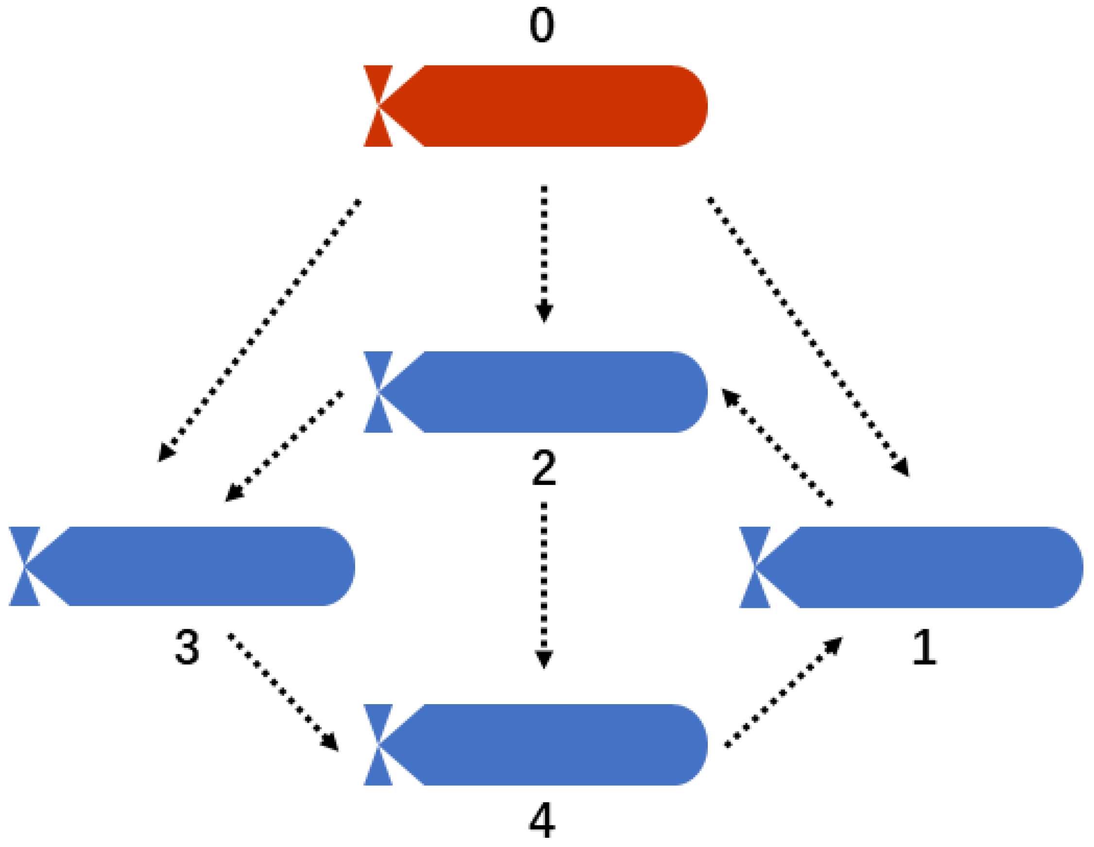
A simulation considering a formation system consisting of four AUVs is designed to accomplish the tracking mission in this section. The simulation simulates the spiral diving mission of the AUV formation. In this work, the CPU type of the computer is Intel(R) Core(TM) i9-13900 HX/2.20 GHz. The selected AUV type is WL-2 [49], and its detailed parameters are listed in Table 1. The information exchange between AUVs is described by Figure 3. To validate the robustness of the developed control scheme, consider the environmental disturbance as Δ i = 0.5 sin t / 30 , 0.15 sin t / 10 , 0.15 cos t / 10 , 0.5 cos t / 10 , 0.5 sin t / 20 T .
The initial positions and relative offsets of each AUV are shown in Table 2 and Table 3, respectively. The upper and lower bounds of the time-varying output constraints are x ¯ i , u t = 2 sin 0.02 t 15 , x ¯ i , q t = 2 sin 0.02 t + 10 , x ¯ i , r t = 2 sin 0.02 t + 2 , x ¯ i , u t = 45 2 sin 0.02 t , x ¯ i , q t = 12 2 sin 0.02 t and, x ¯ i , r t = 17 2 sin 0.02 t , respectively. Moreover, parameters of designed control scheme are shown in Table 4. We assume that the dynamic of the tracked target as follows:
x 0 = 7 cos 0.1 t 27 y 0 = 7 sin 0.1 t z 0 = 0.1 t 2
Figure 4, Figure 5, Figure 6, Figure 7, Figure 8, Figure 9, Figure 10 and Figure 11 exhibit the simulation results. In Figure 4, the 3-D trajectory tracking performance of the AUV formation is demonstrated. It can be shown that the proposed control method can be used to achieve formation tracking control of AUVs. As shown in Figure 4, the red curve represents the tracked target, while the other curves represent the four AUVs. It is expected that the formation will be established within T p s, and the formation can be maintained until the formation tracking task is completed. Subsequent results will further verify the conclusion.
As evidenced in Figure 5, the trajectories of the AUV with time-varying output constraints validate that the proposed method successfully enforces time-varying constraints on AUV position states while accommodating generalized dynamic constraints. Time-varying constraints can be freely adjusted according to user needs without considering their positivity or negativity. It is worth noting that the output constraint boundaries we designed in the simulation have no practical significance, but they satisfy the practical requirements. Because in practice, we often approximate the physical constraints in the environment with smooth functions, and then design control algorithms based on these functions to achieve the control objectives.
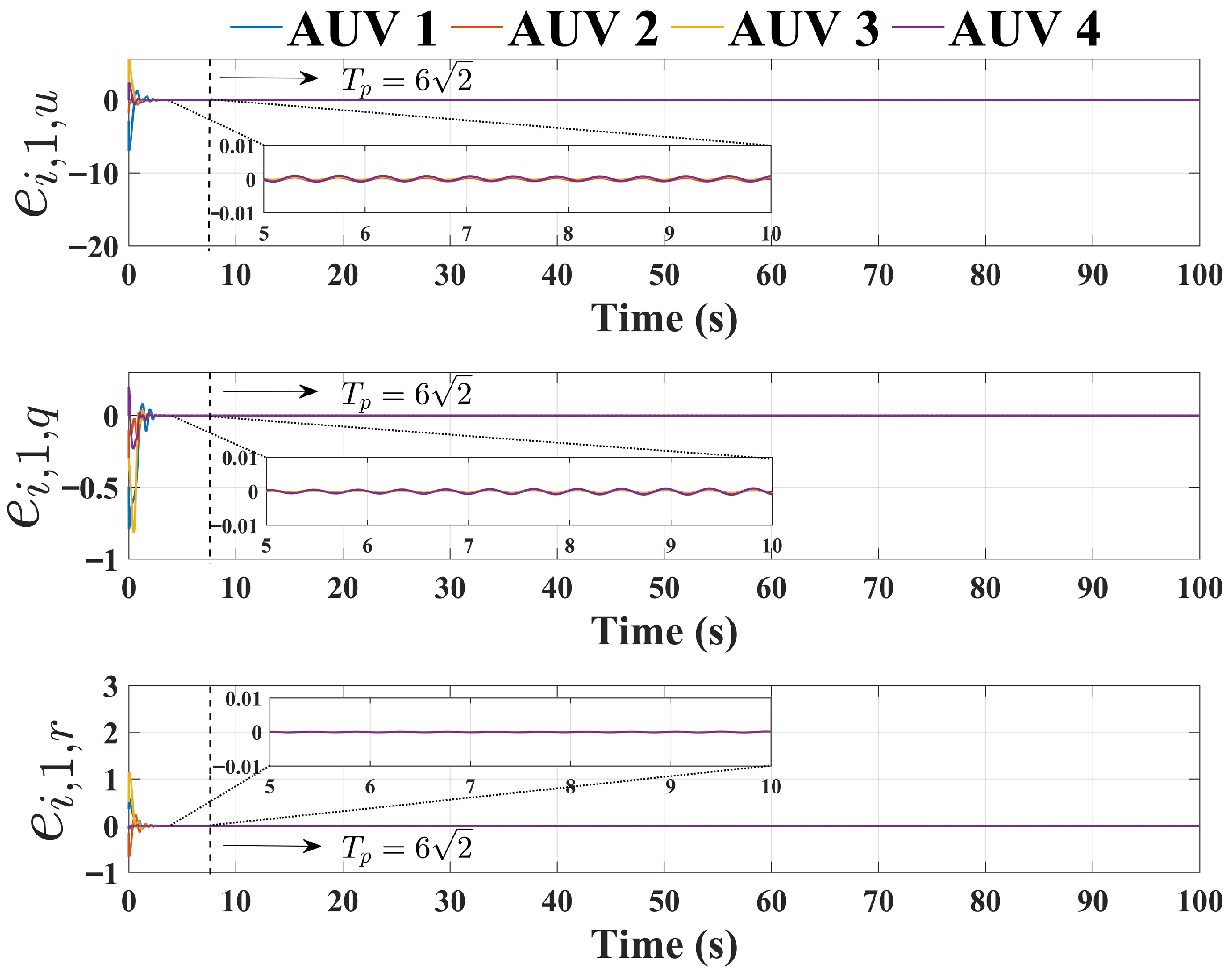
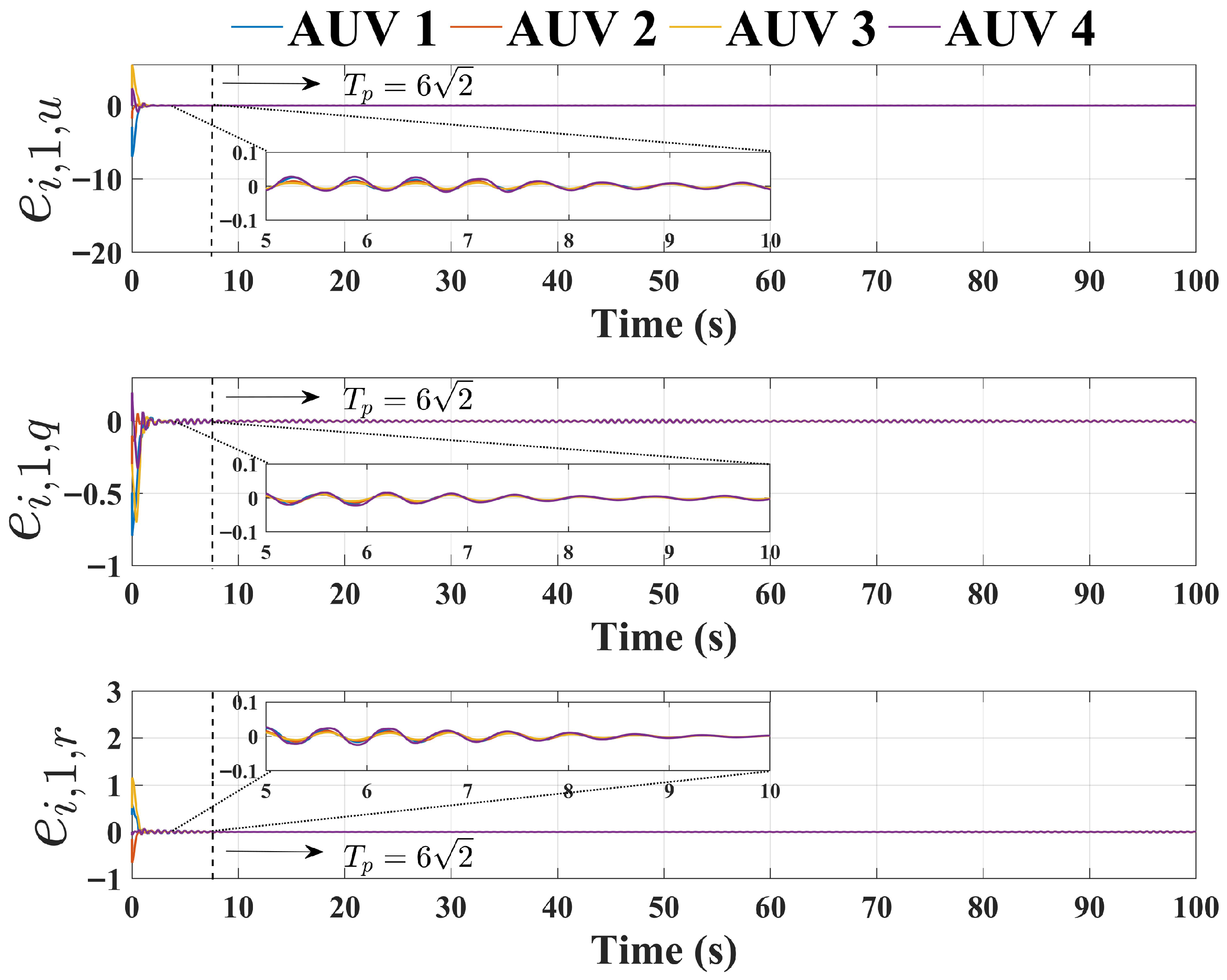
Figure 6 demonstrates the formation tracking error of the AUV. We set the upper bound of convergent time for formation tracking error to T p = 6 2 s. The results reveal that the proposed method can ensure that the formation tracking error converges within T p = 6 2 s. The settling time T p can be freely adjusted by the user. However, it should be noted that, based on (25), when T p is set too small, a greater burden will be added to the actuator. Therefore, from a practical perspective, the time parameter T p should be set based on the performance of the AUV.
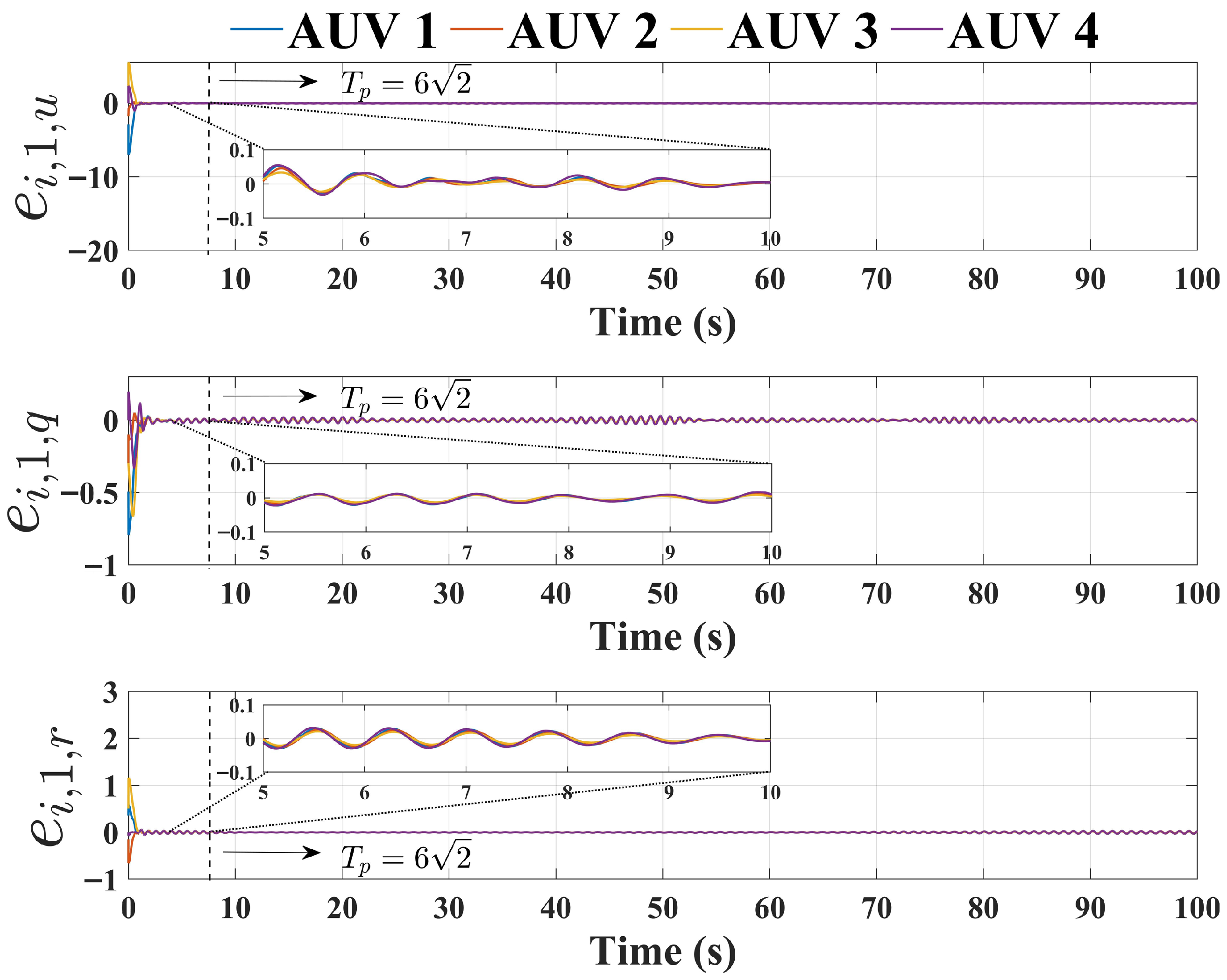
To verify the advantages of the method proposed in this work, we compared the active disturbance rejection formation control method [49] and the fixed-time formation control method [53], with the results shown in Figure 7 and Figure 8. The active disturbance rejection formation control law compared is:
α i = Π i 1 d i + a i 0 κ 1 e i , 1 + ζ i , 2 τ ¯ i , c = M i κ 3 e i , 2 + F ^ i φ i 2 + d i + a i 0 Π i T e i , 1 κ S ϖ i
where κ 1 = 9 and κ 3 = 14 , The remaining parameters are consistent with the parameters listed in Table 4.
The fixed-time formation control law compared is:
α i = Π i 1 d i + a i 0 β 1 D i + 3 h 2 β 2 sig 1 + h e i , 1 + κ 1 e i , 1 + ζ i , 2 τ ¯ i , c = M i β 1 sig 1 h e i , 2 3 h 2 β 2 sig 1 + h e i , 2 M i κ 3 e i , 2 + F ^ i φ i 2 + d i + a i 0 Π i T e i , 1 κ S ϖ i
where the control parameters are consistent with the parameters listed in Table 4.
By analyzing the results in Figure 7 and Figure 8, we can observe that, compared to the results in [49,53], the proposed control method can achieve higher control accuracy within a predefined time, with the formation tracking error being less than 0.01.
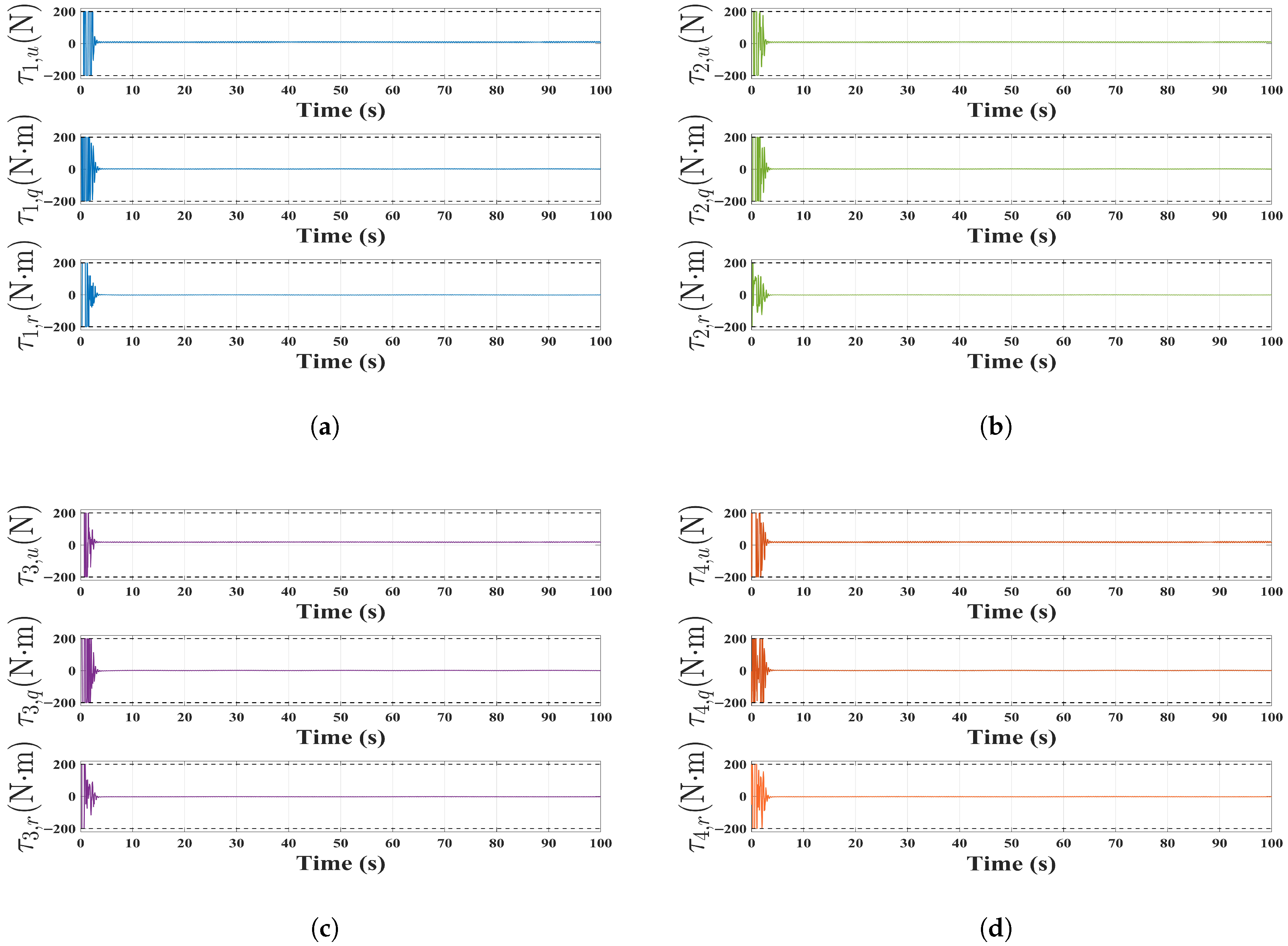
Figure 9 presents the control inputs of each AUV, with actuator saturation limits set to 200 N and 200 N·m. The observed large initial control inputs with rapid variations correspond to significant initial tracking errors. As can be observed in Figure 9, the outputs of all actuators of the AUV remain constant after T p s. There are several reasons for this phenomenon. After tracking the target, each AUV moves in a uniform circular motion in the X-Y plane and dives at a fixed speed in the vertical direction. Therefore, the actuators of the AUV can only output constant force and moment to maintain propulsion or anti-disturbance.
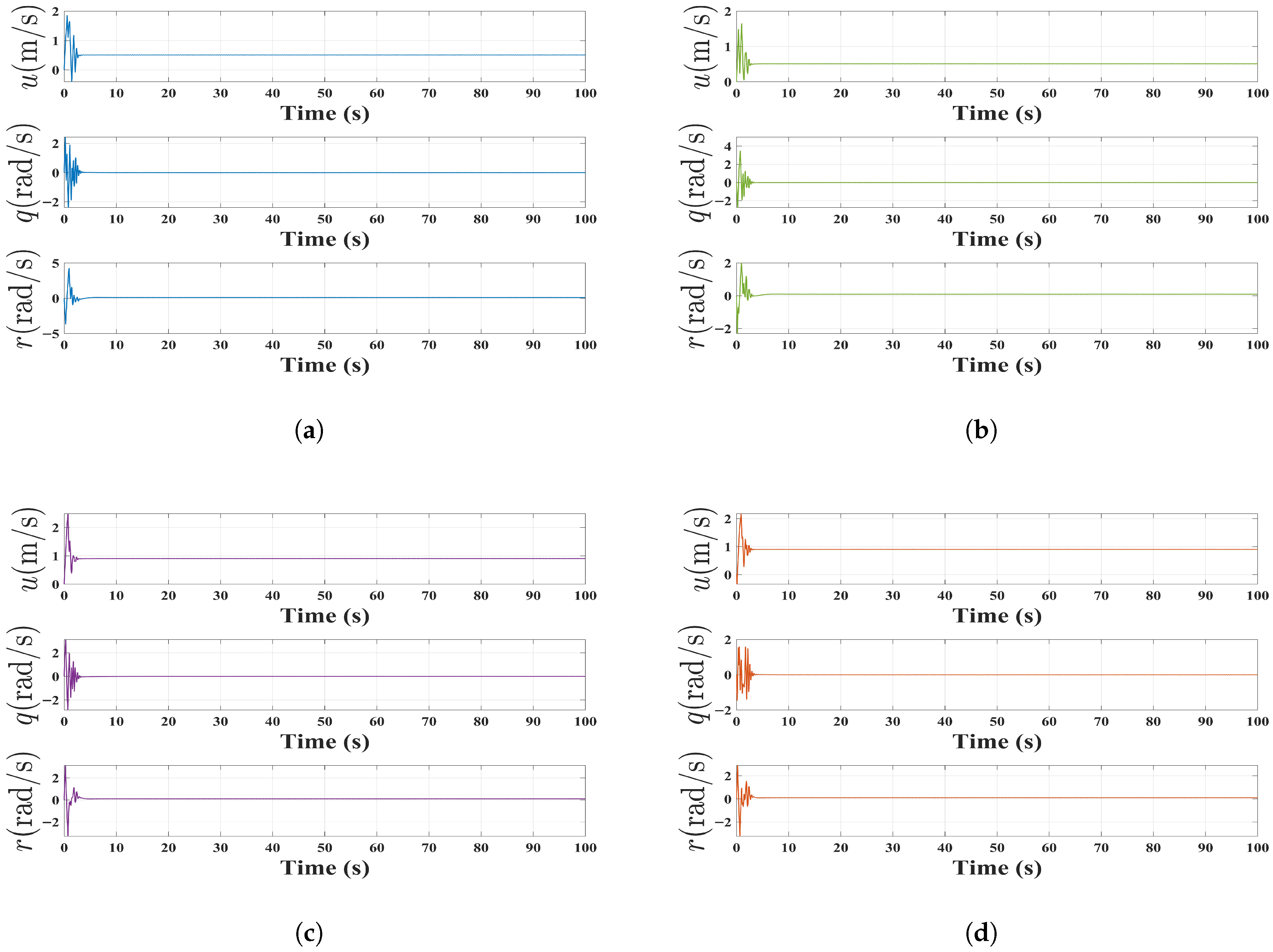
Figure 10 shows observation errors of the FxESO, indicating that the unknown nonlinear dynamics of the AUV can be accurately estimated before T p = 6 2 seconds, which satisfies the requirement of Remark 5. Finally, the linear and angular velocity of the AUV are shown in Figure 11. The results indicate that the velocity of the underactuated AUV formation remain constant after tracking the target, which is consistent with its dynamic characteristics.

5. Conclusions

In this work, a predefined time formation output constraint control method for underactuated AUVs with input saturation has been proposed. A new formation error has been constructed by converting the system to the fully actuated form by coordinate transformation and introducing UTABF to transform the constrained system output into an unconstrained system output. Then, combining ADRC technology, a predefined time formation output constraint control strategy has been proposed. The control law can enhance the anti-disturbance capability of AUVs. A new predefined-time ADS has been proposed. Theoretical results have demonstrated preserved predefined-time tracking performance under saturated actuator. However, due to the working principle of the ESO, the ADRC has limited effectiveness in controlling the system when it is affected by random disturbances or high-frequency disturbances. Additionally, the control method designed based on the backstepping framework is often unable to achieve both low energy consumption and good performance, which is the primary issue to be addressed in the future. Therefore, in the future, we will investigate the output constraint control of AUV formation systems affected by random disturbances and high-frequency disturbances.

Author Contributions

Methodology, Z.F.; software, S.Y. and Y.W.; validation, S.Y.; formal analysis, Y.W.; investigation, Y.W.; resources, Z.F.; writing—original draft, S.Y.; writing—review and editing, Z.F.; supervision, Z.F. All authors have read and agreed to the published version of the manuscript.

Funding

This work was supported in part by “Spring Wild Goose” Plan Project of Heilongjiang Province under Grant CYQN24071.

Data Availability Statement

The original contributions presented in the study are included in the article. Further inquiries can be directed to the corresponding author.

Conflicts of Interest

The authors declare no conflicts of interest.

References

  1. Yang, Y.; Xiao, Y.; Li, T. A survey of autonomous underwater vehicle formation: Performance, formation control, and communication capability. IEEE Commun. Surv. Tutor. 2021, 23, 815–841. [Google Scholar] [CrossRef]
  2. Li, X.; Zhu, D. An adaptive SOM neural network method for distributed formation control of a group of AUVs. IEEE Trans. Ind. Electron. 2018, 65, 8260–8270. [Google Scholar] [CrossRef]
  3. Refsnes, J.E.; Sorensen, A.J.; Pettersen, K.Y. Model-based output feedback control of slender-body underactuated AUVs: Theory and experiments. IEEE Trans. Control Syst. Technol. 2008, 16, 930–946. [Google Scholar] [CrossRef]
  4. Er, M.J.; Gong, H.; Liu, Y.; Liu, T. Intelligent trajectory tracking and formation control of underactuated autonomous underwater vehicles: A critical review. IEEE Trans. Syst. Man Cybern. Syst. 2023, 54, 543–555. [Google Scholar] [CrossRef]
  5. Zhang, J.; Xiang, X.; Li, W.; Zhang, Q. Adaptive saturated path following control of underactuated AUV with unmodeled dynamics and unknown actuator hysteresis. IEEE Trans. Syst. Man Cybern. Syst. 2023, 53, 6018–6030. [Google Scholar] [CrossRef]
  6. Heshmati-Alamdari, S.; Nikou, A.; Dimarogonas, D.V. Robust trajectory tracking control for underactuated autonomous underwater vehicles in uncertain environments. IEEE Trans. Autom. Sci. Eng. 2020, 18, 1288–1301. [Google Scholar] [CrossRef]
  7. Bhat, S.; Panteli, C.; Stenius, I.; Dimarogonas, D.V. Nonlinear model predictive control for hydrobatics: Experiments with an underactuated AUV. J. Field Robot. 2023, 40, 1840–1859. [Google Scholar] [CrossRef]
  8. Rout, R.; Subudhi, B. Design of line-of-sight guidance law and a constrained optimal controller for an autonomous underwater vehicle. IEEE Trans. Circuits Syst. II Express Briefs 2020, 68, 416–420. [Google Scholar] [CrossRef]
  9. Caharija, W.; Pettersen, K.Y.; Bibuli, M.; Calado, P.; Zereik, E.; Braga, J.; Gravdahl, J.T.; Sørensen, A.J.; Milovanović, M.; Bruzzone, G. Integral line-of-sight guidance and control of underactuated marine vehicles: Theory, simulations, and experiments. IEEE Trans. Control Syst. Technol. 2016, 24, 1623–1642. [Google Scholar] [CrossRef]
  10. Chen, B.; Hu, J.; Zhao, Y.; Ghosh, B.K. Finite-time velocity-free rendezvous control of multiple AUV systems with intermittent communication. IEEE Trans. Syst. Man Cybern. Syst. 2022, 52, 6618–6629. [Google Scholar] [CrossRef]
  11. Sedghi, F.; Arefi, M.M.; Abooee, A.; Kaynak, O. Adaptive robust finite-time nonlinear control of a typical autonomous underwater vehicle with saturated inputs and uncertainties. IEEE/ASME Trans. Mechatron. 2020, 26, 2517–2527. [Google Scholar] [CrossRef]
  12. Qin, J.; Du, J.; Li, J. Adaptive finite-time trajectory tracking event-triggered control scheme for underactuated surface vessels subject to input saturation. IEEE Trans. Intell. Transp. Syst. 2023, 24, 8809–8819. [Google Scholar] [CrossRef]
  13. Hu, J.; Chen, B.; Ghosh, B.K. Formation–circumnavigation switching control of multiple ODIN systems via finite-time intermittent control strategies. IEEE Trans. Control Netw. Syst. 2024, 11, 1986–1997. [Google Scholar] [CrossRef]
  14. Gao, Z.; Guo, G. Fixed-time sliding mode formation control of AUVs based on a disturbance observer. IEEE/CAA J. Autom. Sin. 2020, 7, 539–545. [Google Scholar] [CrossRef]
  15. Wang, P.; Yu, C.; Lv, M. Optimized Formation Control of Nonlinear Systems With Full-State Constraints Using Adaptive Fixed-Time Techniques. IEEE Trans. Autom. Sci. Eng. 2025, 22, 3331–3344. [Google Scholar] [CrossRef]
  16. Ju, X.; Jiang, Y.; Jing, L.; Liu, P. Quantized predefined-time control for heavy-lift launch vehicles under actuator faults and rate gyro malfunctions. ISA Trans. 2023, 138, 133–150. [Google Scholar] [CrossRef]
  17. Guo, C.; Hu, J. Time base generator-based practical predefined-time stabilization of high-order systems with unknown disturbance. IEEE Trans. Circuits Syst. II Express Briefs 2023, 70, 2670–2674. [Google Scholar] [CrossRef]
  18. Yu, C.; Xiang, X.; Wilson, P.A.; Zhang, Q. Guidance-error-based robust fuzzy adaptive control for bottom following of a flight-style AUV with saturated actuator dynamics. IEEE Trans. Cybern. 2019, 50, 1887–1899. [Google Scholar] [CrossRef]
  19. Zong, G.; Sun, H.; Nguang, S.K. Decentralized adaptive neuro-output feedback saturated control for INS and its application to AUV. IEEE Trans. Neural Netw. Learn. Syst. 2021, 32, 5492–5501. [Google Scholar] [CrossRef]
  20. Van, M.; Sun, Y.; Mcllvanna, S.; Nguyen, M.N.; Zocco, F.; Liu, Z. Control of multiple AUV systems with input saturations using distributed fixed-time consensus fuzzy control. IEEE Trans. Fuzzy Syst. 2024, 32, 3142–3153. [Google Scholar] [CrossRef]
  21. Ebrahimpour, M.; Lungu, M. Fault-Tolerant Robust Fast Finite-Time Path-Following Control for Underactuated AUVs With Actuator Dynamics and Saturation. J. Field Robot. 2025. [Google Scholar] [CrossRef]
  22. Alattas, K.A.; Vu, M.T.; Mofid, O.; El-Sousy, F.F.; Alanazi, A.K.; Awrejcewicz, J.; Mobayen, S. Adaptive nonsingular terminal sliding mode control for performance improvement of perturbed nonlinear systems. Mathematics 2022, 10, 1064. [Google Scholar] [CrossRef]
  23. Liu, H.; Zhen, S.; Liu, X.; Zheng, H.; Gao, L.; Chen, Y.H. Robust approximate constraint following control design for collaborative robots system and experimental validation. Robotica 2024, 42, 3957–3975. [Google Scholar] [CrossRef]
  24. Wang, J.; Dong, H.; Chen, F.; Vu, M.T.; Shakibjoo, A.D.; Mohammadzadeh, A. Formation control of non-holonomic mobile robots: Predictive data-driven fuzzy compensator. Mathematics 2023, 11, 1804. [Google Scholar] [CrossRef]
  25. Qian, Y.; Hu, D.; Chen, Y.; Fang, Y.; Hu, Y. Adaptive neural network-based tracking control of underactuated offshore ship-to-ship crane systems subject to unknown wave motions disturbances. IEEE Trans. Syst. Man Cybern. Syst. 2021, 52, 3626–3637. [Google Scholar] [CrossRef]
  26. Shen, Z.; Zhou, L.; Yang, Y.; Liu, Y.; Yu, H. Dynamic event-triggered ADP optimized tracking control of marine surface vessels with asymmetric time-varying full-state constraint. IEEE Trans. Intell. Transp. Syst. 2024, 25, 7352–7362. [Google Scholar] [CrossRef]
  27. Xu, L.X.; Ma, H.J.; Guo, D.; Xie, A.H.; Song, D.L. Backstepping sliding-mode and cascade active disturbance rejection control for a quadrotor UAV. IEEE/ASME Trans. Mechatron. 2020, 25, 2743–2753. [Google Scholar] [CrossRef]
  28. Liu, C.; Yue, X.; Zhang, J.; Shi, K. Active disturbance rejection control for delayed electromagnetic docking of spacecraft in elliptical orbits. IEEE Trans. Aerosp. Electron. Syst. 2021, 58, 2257–2268. [Google Scholar] [CrossRef]
  29. Liu, Y.; Li, W.; Dong, X.; Ren, Z. Resilient formation tracking for networked swarm systems under malicious data deception attacks. Int. J. Robust Nonlinear Control 2025, 35, 2043–2052. [Google Scholar] [CrossRef]
  30. Chen, J.; Li, M.; Marcantoni, M.; Jayawardhana, B.; Wang, Y. Range-only Distributed Safety-Critical Formation Control based on Contracting Bearing Estimators and Control Barrier Functions. IEEE Internet Things J. 2025. [Google Scholar] [CrossRef]
  31. Ren, B.; Ge, S.S.; Tee, K.P.; Lee, T.H. Adaptive neural control for output feedback nonlinear systems using a barrier Lyapunov function. IEEE Trans. Neural Netw. 2010, 21, 1339–1345. [Google Scholar] [PubMed]
  32. Liu, Z.; Lai, G.; Zhang, Y.; Chen, C.L.P. Adaptive neural output feedback control of output-constrained nonlinear systems with unknown output nonlinearity. IEEE Trans. Neural Netw. Learn. Syst. 2015, 26, 1789–1802. [Google Scholar] [PubMed]
  33. Li, B.; Wen, S.; Yan, Z.; Wen, G.; Huang, T. A survey on the control lyapunov function and control barrier function for nonlinear-affine control systems. IEEE/CAA J. Autom. Sin. 2023, 10, 584–602. [Google Scholar] [CrossRef]
  34. Cruz-Ortiz, D.; Chairez, I.; Poznyak, A. Sliding-mode control of full-state constraint nonlinear systems: A barrier Lyapunov function approach. IEEE Trans. Syst. Man Cybern. Syst. 2022, 52, 6593–6606. [Google Scholar] [CrossRef]
  35. Fuentes-Aguilar, R.Q.; Chairez, I. Adaptive tracking control of state constraint systems based on differential neural networks: A barrier Lyapunov function approach. IEEE Trans. Neural Netw. Learn. Syst. 2020, 31, 5390–5401. [Google Scholar] [CrossRef]
  36. Liang, X.; Ge, S.S. Zone barrier Lyapunov functions for state constrained systems. IEEE Trans. Instrum. Meas. 2023, 72, 3001911. [Google Scholar] [CrossRef]
  37. Sun, W.; Su, S.F.; Wu, Y.; Xia, J.; Nguyen, V.T. Adaptive fuzzy control with high-order barrier Lyapunov functions for high-order uncertain nonlinear systems with full-state constraints. IEEE Trans. Cybern. 2019, 50, 3424–3432. [Google Scholar] [CrossRef] [PubMed]
  38. Liu, Y.J.; Tong, S.; Chen, C.P.; Li, D.J. Adaptive NN control using integral barrier Lyapunov functionals for uncertain nonlinear block-triangular constraint systems. IEEE Trans. Cybern. 2016, 47, 3747–3757. [Google Scholar] [CrossRef]
  39. Yuan, F.; Liu, Y.J.; Liu, L.; Lan, J.; Li, D.; Tong, S.; Chen, C.P. Adaptive neural consensus tracking control for nonlinear multiagent systems using integral barrier Lyapunov functionals. IEEE Trans. Neural Netw. Learn. Syst. 2021, 34, 4544–4554. [Google Scholar] [CrossRef]
  40. Zhao, K.; Song, Y. Neuroadaptive robotic control under time-varying asymmetric motion constraints: A feasibility-condition-free approach. IEEE Trans. Autom. Control 2020, 50, 15–24. [Google Scholar] [CrossRef]
  41. Feng, Z.; Li, R.B.; Zhang, W.; Qiu, J.; Jiang, Z. Neuroadaptive output-feedback tracking control for stochastic nonlower triangular nonlinear systems with dead-zone input. IEEE Trans. Cybern. 2024, 54, 7839–7850. [Google Scholar] [CrossRef]
  42. Long, H.; Zhang, P.; Guo, T.; Zhao, J. Saturated Adaptive Fuzzy Fixed-Time Nonsingular Integral Terminal Sliding-Mode Control of AUVs. IEEE Trans. Cybern. 2025, 55, 1634–1647. [Google Scholar] [CrossRef]
  43. Wang, L.; Zhu, D.; Pang, W.; Luo, C. A novel obstacle avoidance consensus control for multi-AUV formation system. IEEE/CAA J. Autom. Sin. 2023, 10, 1304–1318. [Google Scholar] [CrossRef]
  44. Feng, Z.; Yao, S. Dynamic event-triggered active disturbance rejection formation control for constrained underactuated AUVs. IEEE/CAA J. Autom. Sin. 2025, 12, 460–462. [Google Scholar] [CrossRef]
  45. Zhang, Z.; Wu, Y. Adaptive fuzzy tracking control of autonomous underwater vehicles with output constraints. IEEE Trans. Fuzzy Syst. 2020, 29, 1311–1319. [Google Scholar] [CrossRef]
  46. Dai, S.L.; He, S.; Wang, M.; Yuan, C. Adaptive neural control of underactuated surface vessels with prescribed performance guarantees. IEEE Trans. Neural Netw. Learn. Syst. 2018, 30, 3686–3698. [Google Scholar] [CrossRef] [PubMed]
  47. Zhang, J.; Hua, C.; Sun, Z.; Zhang, B.; Luo, X.; Chen, J. Hemispherical Space Constrained Velocity Free Control of UUVs via a Coupled Funnel Scheme. IEEE Trans. Ind. Electron. 2024, 72, 7452–7461. [Google Scholar] [CrossRef]
  48. Zhu, Z.; Ma, J.; Sun, H.; Wang, W.; Zhao, H.; Lee, T.H. Game-theoretic optimization toward diffeomorphism-based robust control of fuzzy dynamical systems with state and input constraints. IEEE Trans. Fuzzy Syst. 2023, 32, 373–387. [Google Scholar] [CrossRef]
  49. Xu, J.; Cui, Y.; Xing, W.; Huang, F.; Du, X.; Yan, Z.; Wu, D. Distributed active disturbance rejection formation containment control for multiple autonomous underwater vehicles with prescribed performance. Ocean Eng. 2022, 259, 112057. [Google Scholar] [CrossRef]
  50. Du, J.; Li, J.; Lewis, F.L. Distributed 3-D time-varying formation control of underactuated AUVs with communication delays based on data-driven state predictor. IEEE Trans. Ind. Inform. 2022, 19, 6963–6971. [Google Scholar] [CrossRef]
  51. Gao, Z.; Guo, G. Command-filtered fixed-time trajectory tracking control of surface vehicles based on a disturbance observer. Int. J. Robust Nonlinear Control 2019, 29, 4348–4365. [Google Scholar] [CrossRef]
  52. Zhang, J.; Yu, S.; Yan, Y. Fixed-time extended state observer-based trajectory tracking and point stabilization control for marine surface vessels with uncertainties and disturbances. Ocean Eng. 2019, 186, 106109. [Google Scholar] [CrossRef]
  53. Xu, H.; Cui, G.; Ma, Q.; Li, Z.; Hao, W. Fixed-time disturbance observer-based distributed formation control for multiple QUAVs. IEEE Trans. Circuits Syst. II Express Briefs 2023, 70, 2181–2185. [Google Scholar] [CrossRef]
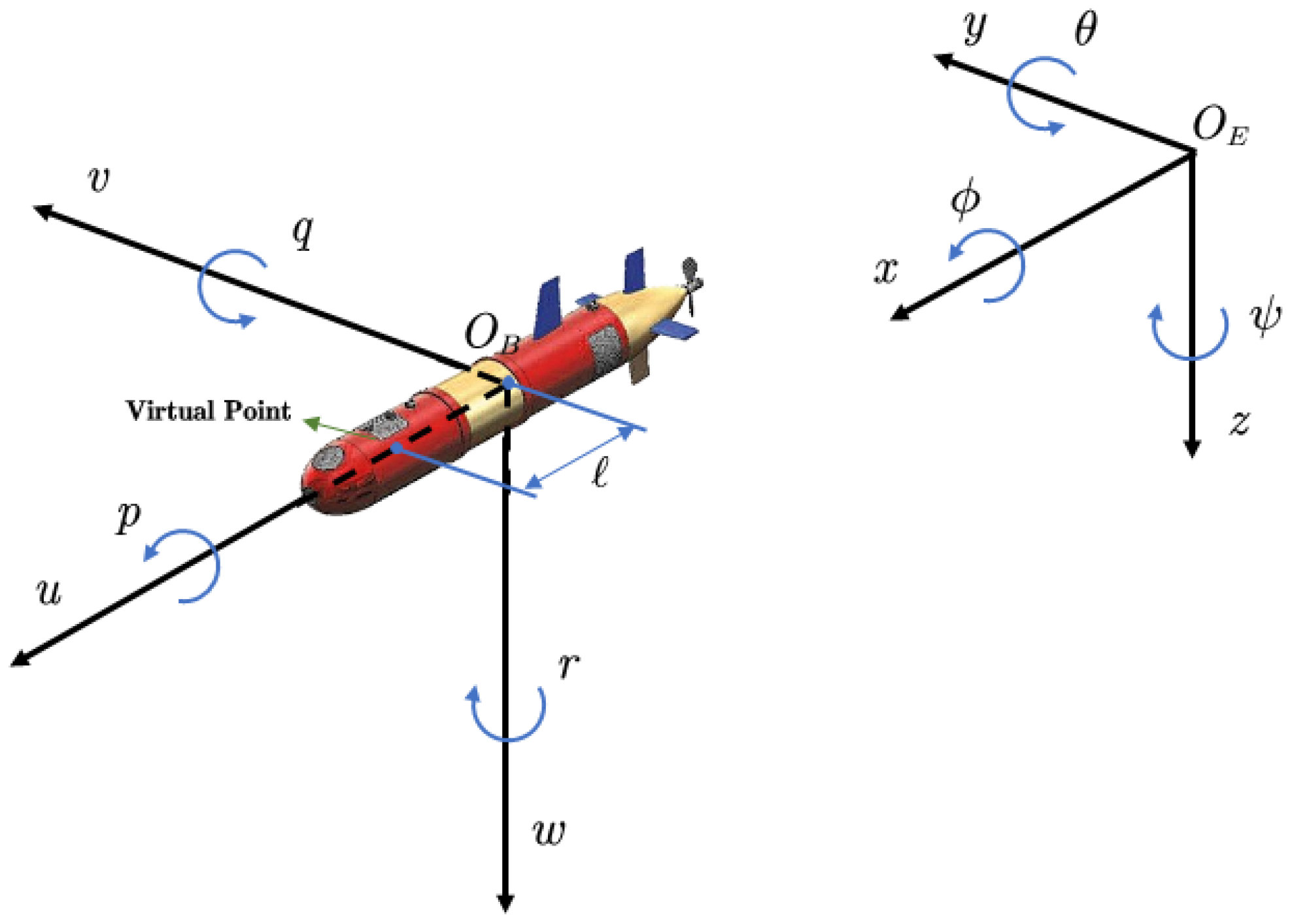
Figure 1. Earth and body coordinate systems of an AUV.
Jmse 13 01607 g001
Figure 2. Diagram of control framework.
Jmse 13 01607 g002
Figure 3. The information exchange between AUVs.
Jmse 13 01607 g003
Figure 4. 3-D trajectories of AUVs and target.
Jmse 13 01607 g004
Figure 5. Trajectories of the position for AUVs.
Jmse 13 01607 g005
Figure 6. The formation tracking error of AUVs when applying the method proposed in this paper.
Jmse 13 01607 g006
Figure 7. The formation tracking error of AUVs when applying the method proposed in [49].
Jmse 13 01607 g007
Figure 8. The formation tracking error of AUVs when applying the method proposed in [53].
Jmse 13 01607 g008
Figure 9. Control forces and moments of the AUV. (a) Control forces and moments of the AUV 1. (b) Control forces and moments of the AUV 2. (c) Control forces and moments of the AUV 3. (d) Control forces and moments of the AUV 4.
Jmse 13 01607 g009
Figure 10. The observation error of the FxESO.
Jmse 13 01607 g010
Figure 11. The linear and angular velocity of AUVs. (a) The velocity of AUV 1. (b) The velocity of AUV 2. (c) The velocity of AUV 3. (d) The velocity of AUV 4.
Jmse 13 01607 g011
Table 1. Values of the ith AUV parameters.
ParametersValuesParametersValues
m i 45 k g Y o i 45 kg s 1
X u i −2.5 k g Y | o | v i 194.8 kg m 1
Y o i −49 k g Z w i 44.7 kg s 1
Z w i −49 k g Z | w | w i 41.7 kg m 1
I y i 6.75 kg m 2 M q i 23.8 kg m 2 s 1 rad 1
M q i −6.75 kg m 2 M | q | q i 3.9 kg m 2 rad −2
I z i 6.75 kg m 2 N r i 2.72 kg m 2 s 1 rad 1
N r i −6.75 kg m 2 N | r | r i 4.9 kg m 2 rad 2
X u i 13.5 kg s 1 X | u | u i 6.4 kg m 1
Table 2. Initial positions for the AUV.
x i 0 Values
x 1 0 22.5 , 0.8 , 0.5 , 0 , 0.5 π T
x 2 0 22.3 , 0.6 , 3.2 , 0 , 0.5 π T
x 3 0 17.7 , 0.6 , 0.3 , 0 , 0.5 π T
x 4 0 17.8 , 0.5 , 2.8 , 0 , 0.5 π T
Table 3. Desired time-varying offset vectors.
δ i t Values
δ 1 t 2 cos t / 10 , 2 sin t / 10 , 1 , 0 , 0 T
δ 2 t 2 cos t / 10 , 2 sin t / 10 , 1 , 0 , 0 T
δ 3 t 2 cos t / 10 , 2 sin t / 10 , 1 , 0 , 0 T
δ 4 t 2 cos t / 10 , 2 sin t / 10 , 1 , 0 , 0 T
Table 4. Parameters of control scheme.
ComponentsParameters
Virtual control law (14) h = 1 / 11 , κ 1 = 2 , T c = 6 , β 1 = 1 , β 2 = 9 , ε 1 = 0.02
TD (20) λ 1 = 1 , λ 2 = 4 , λ 3 = 8 , λ 4 = 24 , p 1 = 5 / 7 , q 1 = 5 / 3 , p 2 = 5 / 9 , q 2 = 7 / 3
ADS (21) σ i = 20 , κ 2 = 1
ESO (24) K 1 = K 2 = 1 , K 3 = K 4 = 10 , K 0 = 0.8 , ς 1 = 0.72 , ς 2 = 1.39
Command control law (25) κ S = 0.1 , κ 3 = 4
Disclaimer/Publisher’s Note: The statements, opinions and data contained in all publications are solely those of the individual author(s) and contributor(s) and not of MDPI and/or the editor(s). MDPI and/or the editor(s) disclaim responsibility for any injury to people or property resulting from any ideas, methods, instructions or products referred to in the content.