
Novel Hybrid Aquatic–Aerial Vehicle to Survey in High Sea States: Initial Flow Dynamics on Dive and Breach


 , , and
Abstract
1. Introduction and Literature
2. Methodology
2.1. Numerical Setup and Governing Equations
2.2. Simulation Setup
2.2.1. Model Geometry and Parameters
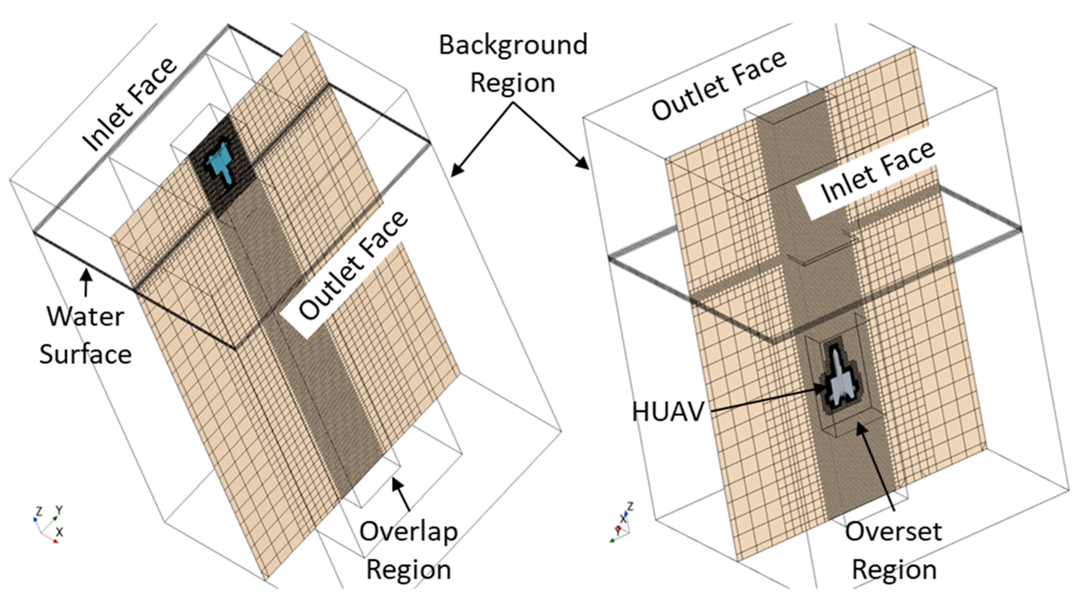
2.2.2. Grid Generation and Boundary Conditions
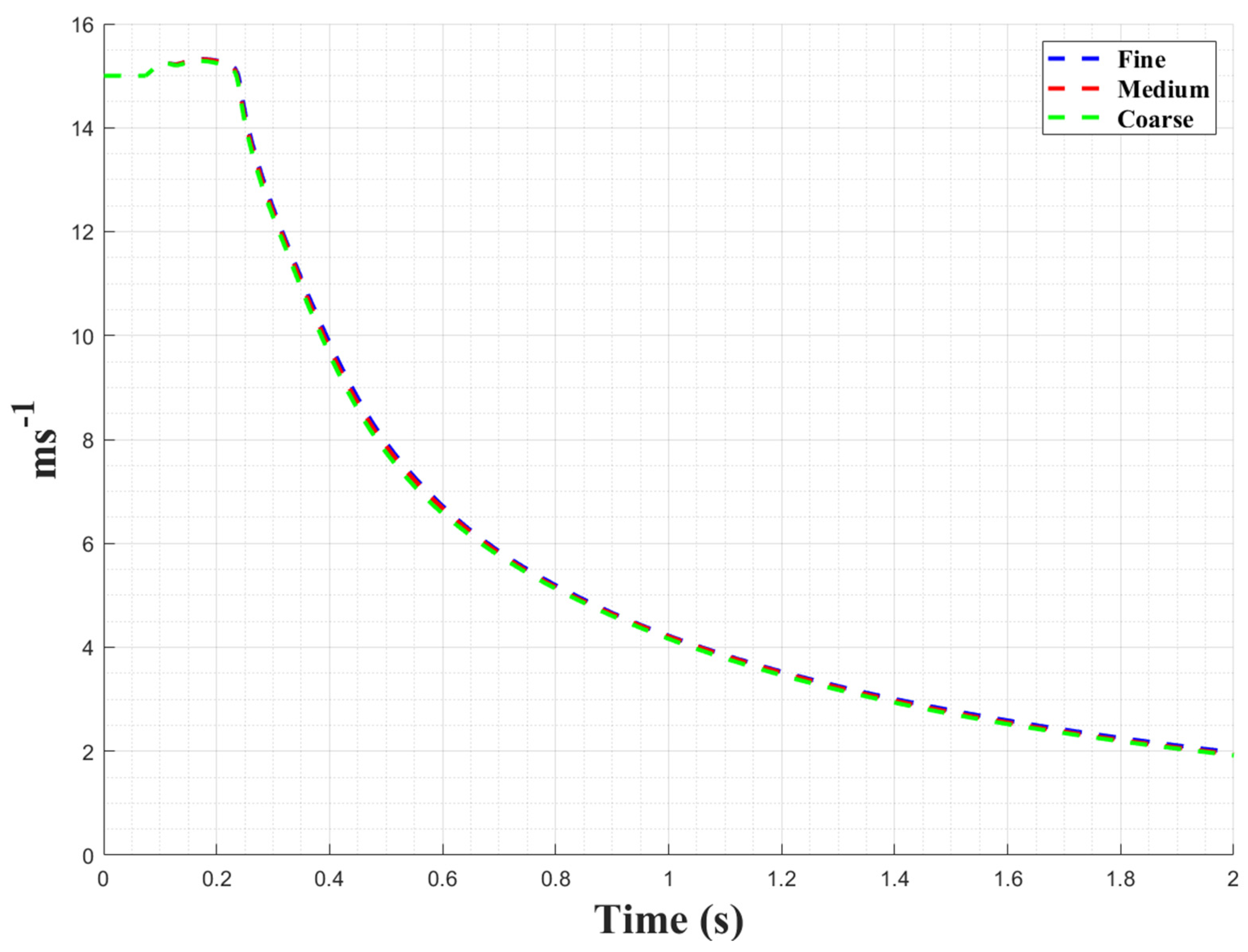
3. Grid Convergence
4. Results and Discussion
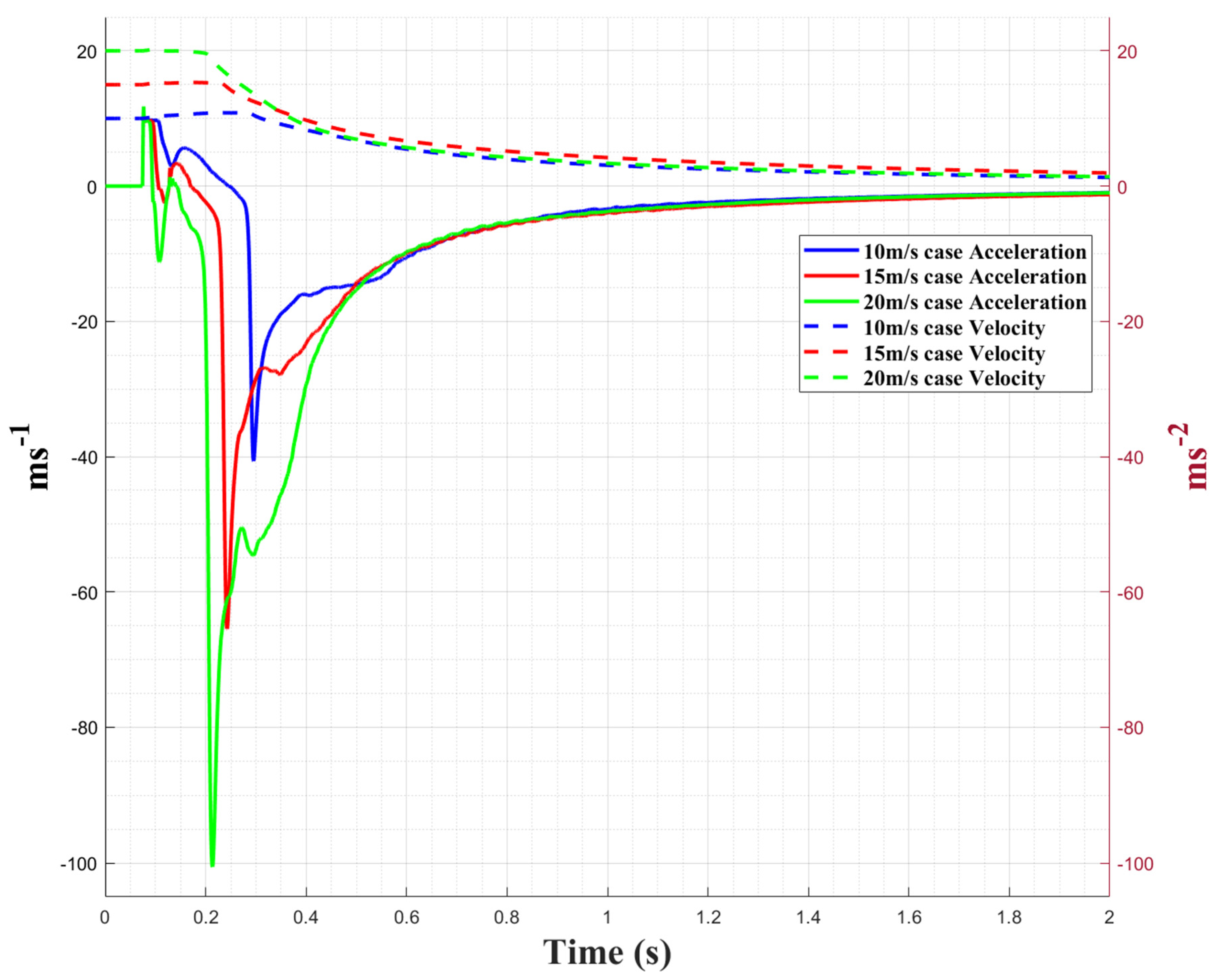
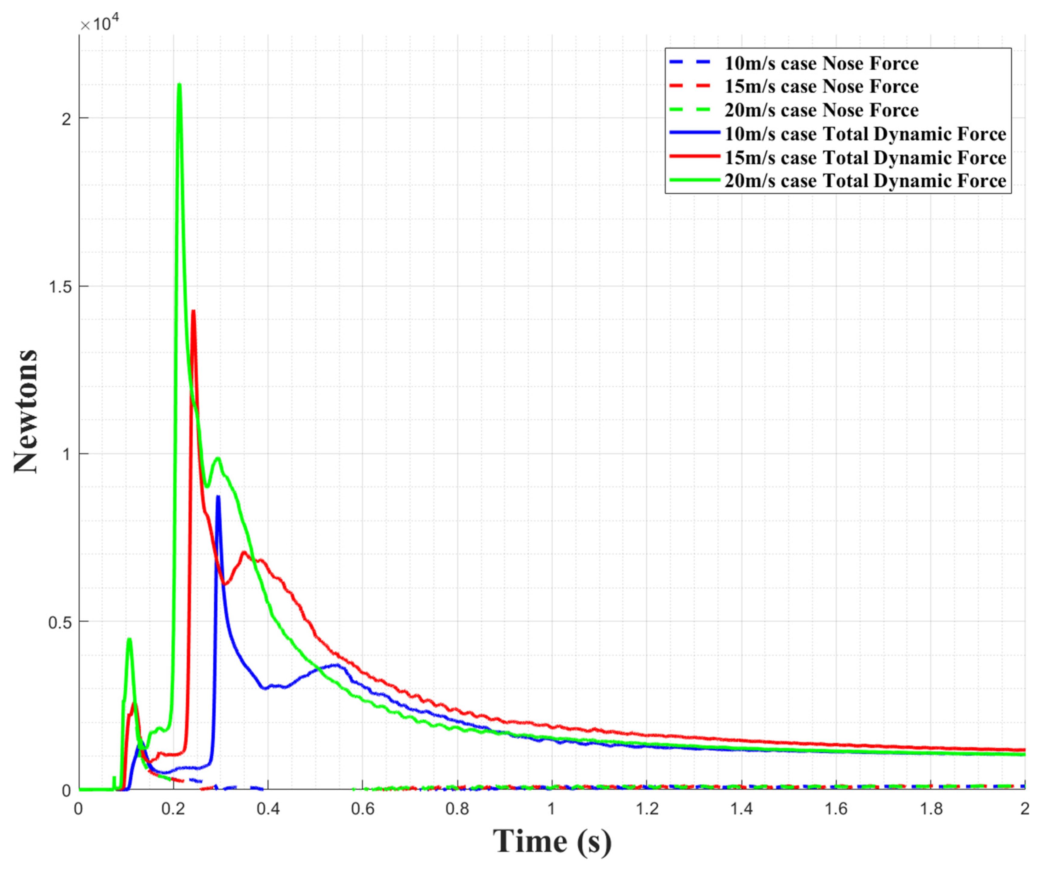
4.1. Penetration
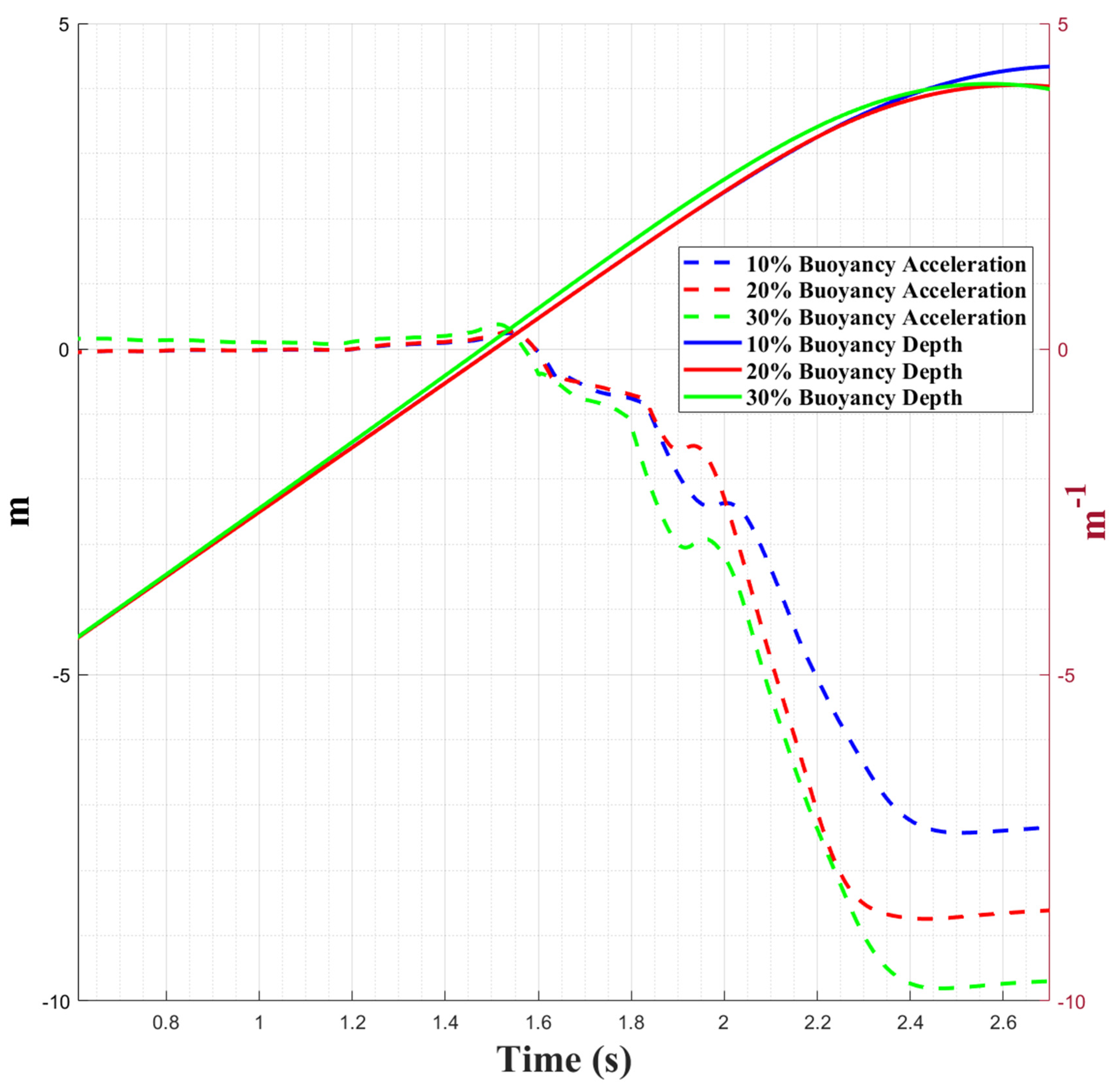
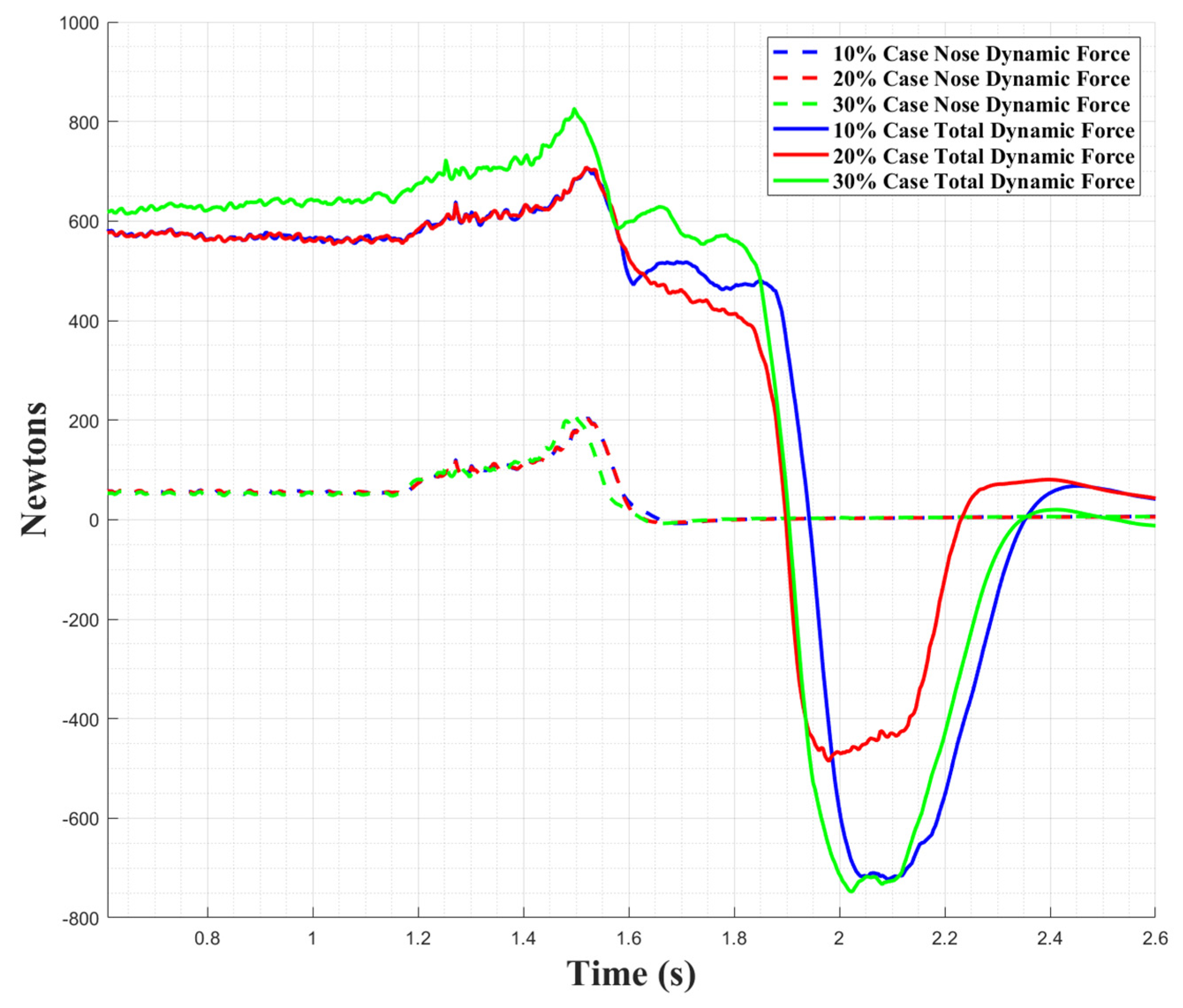
4.2. Breaching
4.3. Limitations and Risks
5. Conclusions
Author Contributions
Funding
Data Availability Statement
Acknowledgments
Conflicts of Interest
Nomenclature
| bi | Coordinate body forces per unit mass (Ni kg−1) |
| ε | Turbulent kinetic dissipation rate |
| ii | Cartesian unit vector in the direction of X |
| k | Turbulence kinetic energy |
| P | Pressure (N m−2) (Pa) |
| p | Mean pressure (N m−2) |
| S | Modulus of the mean strain rate tensor |
| T | Turbulent time scale (s) |
| t | Time scale (s) |
| εi | Newtonian stress tensor Cartesian component |
| ui | Cartesian components of the averaged velocity (m s−1) |
| v | Fluid velocity (m s−1) |
| Mean velocity (m s−1) | |
| u | Kinematic viscosity (N s m−2) |
| μ | Dynamic viscosity (Pa s) |
| μt | Turbulent eddy Viscosity |
| r | Fluid density (kg m−3) |
| ω | Turbulence specific rate of dissipation |
References
- Primrose, S.B. Biomimetics: Nature-Inspired Design and Innovation; Wiley: Newark, NJ, USA, 2020. [Google Scholar]
- Yang, X.; Wang, T.; Liang, J.; Yao, G.; Liu, M. Survey on the novel hybrid aquatic–aerial amphibious aircraft: Aquatic unmanned aerial vehicle (AquaUAV). Prog. Aerosp. Sci. 2015, 74, 131–151. [Google Scholar] [CrossRef]
- Yao, G.; Li, Y.; Zhang, H.; Jiang, Y.; Wang, T.; Sun, F.; Yang, X. Review of hybrid aquatic-aerial vehicle (HAAV): Classifications, current status, applications, challenges and technology perspectives. Prog. Aerosp. Sci. 2023, 139, 100902. [Google Scholar] [CrossRef]
- Joiner, K.F.; Swidan, A. Conceptualising a Hybrid Flying and Diving Craft. J. Mar. Sci. Eng. 2023, 11, 1541. [Google Scholar] [CrossRef]
- Boom, B.; Truscott, T.; Fish, F.; Summers, A.; Habtour, E. Water Entry Dynamics of Avian Inspired Divers. In Proceedings of the ASME 2023 Conference on Smart Materials, Adaptive Structures and Intelligent Systems, Austin, TX, USA, 11–13 September 2023. [Google Scholar] [CrossRef]
- Ropert-Coudert, Y.; Grémillet, D.; Ryan, P.; Kato, A.; Naito, Y.; Le Maho, Y. Between air and water: The plunge dive of the Cape Gannet Morus capensis. Ibis 2004, 146, 281–290. [Google Scholar] [CrossRef]
- Yang, X.; Liang, J.; Wang, T.; Yao, G.; Zhao, W.; Zhang, Y.; Han, C. Computational simulation of a submersible unmanned aerial vehicle impacting with water. In Proceedings of the IEEE International Conference on Robotics and Biomimetics (ROBIO), Shenzhen, China, 12–14 December 2013; pp. 1138–1143. [Google Scholar] [CrossRef]
- Machovsky-Capuska, G.E.; Howland, H.C.; Raubenheimer, D.; Vaughn-Hirshorn, R.; Würsig, B.; Hauber, M.E.; Katzir, G. Visual accommodation and active pursuit of prey underwater in a plunge-diving bird: The Australasian gannet. Proc. R. Soc. B Biol. Sci. 2012, 279, 4118–4125. [Google Scholar] [CrossRef]
- Liang, J.; Yao, G.; Wang, T.; Yang, X.; Zhao, W.; Song, G.; Zhang, Y. Wing load investigation of the plunge-diving locomotion of a gannet Morus inspired submersible aircraft. Sci. China Technol. Sci. 2014, 57, 390–402. [Google Scholar] [CrossRef]
- Kooyman, G.L.; Drabek, C.M.; Elsner, R.; Campbell, W.B. Diving behavior of the emperor penguin, Aptenodytes forsteri. Auk 1971, 88, 775–795. [Google Scholar] [CrossRef]
- Sato, K.; Ponganis, P.J.; Habara, Y.; Naito, Y. Emperor penguins adjust swim speed according to the above-water height of ice holes through which they exit. J. Exp. Biol. 2005, 208, 2549–2554. [Google Scholar] [CrossRef]
- Waseem, R.; Malik, T. US-China Strategic Competition: Conventional Deterrence and the Changing Face of Modern Warfare. J. Humanit. Soc. Sci. 2024, 32, 161–183. [Google Scholar]
- Bogue, R. Political tensions and technological innovation driving the military robot business. Ind. Robot Int. J. Robot. Res. Appl. 2024, 51, 189–195. [Google Scholar] [CrossRef]
- Chávez, K.; Swed, O. The Empirical Determinants of Violent Nonstate Actor Drone Adoption. Armed Forces Soc. 2024, 50, 883–912. [Google Scholar] [CrossRef]
- Lu, D.; Xiong, C.; Zeng, Z.; Lian, L. A multimodal aerial underwater vehicle with extended endurance and capabilities. In Proceedings of the International Conference on Robotics and Automation (ICRA), Montreal, QC, Canada, 20–24 May 2019; pp. 4674–4680. [Google Scholar] [CrossRef]
- Lu, D.; Xiong, C.; Zhou, H.; Lyu, C.; Hu, R.; Yu, C.; Zeng, Z.; Lian, L. Design, fabrication, and characterization of a multimodal hybrid aerial underwater vehicle. Ocean Eng. 2021, 219, 108324. [Google Scholar] [CrossRef]
- Lyu, C.; Lu, D.; Xiong, C.; Hu, R.; Jin, Y.; Wang, J.; Zeng, Z.; Lian, L. Toward a gliding hybrid aerial underwater vehicle: Design, fabrication, and experiments. J. Field Robot. 2022, 39, 543–556. [Google Scholar] [CrossRef]
- Jin, Y.; Bi, Y.; Lyu, C.; Bai, Y.; Zeng, Z.; Lian, L. Nezha-IV: A hybrid aerial underwater vehicle in real ocean environments. J. Field Robot. 2024, 41, 420–442. [Google Scholar] [CrossRef]
- Jin, Y.; Zeng, Z.; Lian, L. Nezha-SeaDart: A tail-sitting fixed-wing vertical takeoff and landing hybrid aerial underwater vehicle. J. Field Robot. 2024, 42, 137–152. [Google Scholar] [CrossRef]
- Narayanan, A.; Rajeshirke, P.; Sharma, A.; Pestonjamasp, K. Survey of the emerging bio-inspired Unmanned Aerial Underwater Vehicles. In Proceedings of the 2nd International Conference on Emerging Trends in Manufacturing, Engines and Modelling (ICEMEM 2019), Mumbai, India, 23–24 December 2019. [Google Scholar] [CrossRef]
- Bi, Y.; Lu, D.; Zeng, Z.; Lian, L. Dynamics and control of hybrid aerial underwater vehicle subject to disturbances. Ocean Eng. 2022, 250, 110933. [Google Scholar] [CrossRef]
- Carroll, N.J.; Champ, D.; Gebers, A.; Jewson, E.; Patel, P.; Shpak, G.; Joiner, K.F.; Swidan, A. Low-Observable Submersible Sea-plane for Electronics Intelligence (LOSSEI): A conceptual design and analysis. In Proceedings of the 6th SIA Submarine Science, Technology and Engineering Conference (SubSTEC6), Adelaide, Australia, 8–10 November 2021. [Google Scholar]
- Joiner, K.F.; Swidan, A.; Jewson, E.; Carroll, N.; Champ, D.; Shpak, G. Submersible Seaplanes as the Path to Hybrid Flying and Diving Craft. In Proceedings of the ISUDEF 2021—International Symposium on Unmanned Systems and the Defense Industry, Washington, DC, USA, 26–28 October 2021. [Google Scholar]
- Joiner, K.F.; Warren, G.; Truslove, A.; Graco, Q.; Erickson, M.; Lawson, N. Students Design UAV to Target Undersea Threats. 2023. Available online: https://navalinstitute.com.au/students-design-uav-to-target-undersea-threats/ (accessed on 21 August 2023).
- Braggett, G.; Joiner, K.F.; Somerville, A.; Hill, D. Feasibility of Electric Ducted Fans to replace open propellers on an electrified training aircraft. Aerosp. Sci. Technol. 2025; Submitted, TBD. Available online: https://papers.ssrn.com/sol3/papers.cfm?abstract_id=5064869 (accessed on 21 August 2023).
- Fresconi, F.; Fermen-Coker, M. Delivery of Modular Lethality via a Parent-Child Concept. In Proceedings of the AIAA Atmospheric Flight Mechanics Conference, Dallas, TX, USA, 22–26 June 2015. [Google Scholar] [CrossRef]
- Trevithick, J. This Is Our First Look at How General Atomics’ Sparrowhawk Drone Will Get Caught in Mid-Air. Available online: https://www.thedrive.com/the-war-zone/41716/this-is-our-first-look-at-how-general-atomics-sparrowhawk-drone-will-get-caught-in-mid-air (accessed on 21 August 2023).
- Qi, D.; Feng, J.; Xu, B.; Zhang, J.; Li, Y. Investigation of water entry impact forces on airborne-launched AUVs. Eng. Appl. Comput. Fluid Mech. 2016, 10, 473–484. [Google Scholar] [CrossRef]
- Ma, Z.; Hu, J.; Feng, J.; Liu, A.; Chen, G. A longitudinal air–water trans-media dynamic model for slender vehicles under low-speed condition. Nonlinear Dyn. 2020, 99, 1195–1210. [Google Scholar] [CrossRef]
- Wei, J.; Sha, Y.-B.; Hu, X.-Y.; Yao, J.-Y.; Chen, Y.-L. Aerodynamic Numerical Simulation Analysis of Water-Air Two-Phase Flow in Trans-Medium Aircraft. Drones 2022, 6, 236. [Google Scholar] [CrossRef]
- Sun, X.; Cao, J.; Li, Y.; Ling, Y. Efficient prediction method for the water-exit characteristics of unmanned aerial–underwater vehicles. Ocean Eng. 2024, 302, 117403. [Google Scholar] [CrossRef]
- Li, Z.; Zhang, W.; Huang, X.; Ye, X.; Chen, Y.; Jiang, Q. Water-exit dynamics and system identification for a hybrid aerial underwater vehicle. Eng. Appl. Comput. Fluid Mech. 2025, 19, 2512956. [Google Scholar] [CrossRef]
- Wu, X.; Chang, X.; Liu, S.; Yu, P.; Zhou, L.; Tian, W. Numerical Study on the Water Entry Impact Forces of an Air-Launched Underwater Glider under Wave Conditions. Shock Vib. 2022, 2022, 4330043. [Google Scholar] [CrossRef]
- Dong, L.; Wei, Z.; Zhou, H.; Yao, B.; Lian, L. Numerical Study on the Water Entry of a Freely Falling Unmanned Aerial-Underwater Vehicle. J. Mar. Sci. Eng. 2023, 11, 552. [Google Scholar] [CrossRef]
- Liu, B.; Chen, X.; Li, E.; Le, G. Numerical Analysis on Water-Exit Process of Submersible Aerial Vehicle under Different Launch Conditions. J. Mar. Sci. Eng. 2023, 11, 839. [Google Scholar] [CrossRef]
- Yun, H.; Jin, Y.; Xie, H.; Zeng, Z.; Lian, L. Research on the Dynamic Characteristics of the Hybrid Aerial Underwater Vehicle: Low-velocity Water Exit. J. Mar. Sci. Appl. 2025, 24, 323–330. [Google Scholar] [CrossRef]
- Lu, Y.; Hu, J.; Chen, G.; Liu, A.; Feng, J. Optimization of water-entry and water-exit maneuver trajectory for morphing unmanned aerial-underwater vehicle. Ocean Eng. 2022, 261, 112015. [Google Scholar] [CrossRef]
- Liang, X.F.; Yang, J.M.; Li, J.; Xiao, L.F.; Li, X. Numerical simulation of irregular wave-simulating irregular wave train. J. Hydrodyn. 2010, 22, 537–545. [Google Scholar] [CrossRef]
- Ferziger, J.H.; Perić, M.; Street, R.L. Computational Methods for Fluid Dynamics, 4th ed.; Springer International Publishing: Berlin/Heidelberg, Germany, 2020. [Google Scholar]
- Tu, J.; Yeoh, G.H.; Liu, C. Computational Fluid Dynamics—A Practical Approach, 3rd ed.; Elsevier: Amsterdam, The Netherlands, 2018. [Google Scholar]
- Wilcox, D.C. Turbulence Modeling for CFD, 3rd ed.; DCW Industries: Lake Arrowhead, CA, USA, 2006. [Google Scholar]
- Versteeg, H.K.; Malalasekera, W. An Introduction to Computational Fluid Dynamics: The Finite Volume Method, 2nd ed.; Pearson Education Ltd.: London, UK, 2007. [Google Scholar]
- Menter, F.R. Two-equation eddy-viscosity turbulence models for engineering applications. AIAA J. 1994, 32, 1598–1605. [Google Scholar] [CrossRef]
- Siemens STAR-CCM, Version 2021.1. 2020, Online User Guide. Available online: https://community.sw.siemens.com/s/question/0D5KZ000006pFuh0AE/simcenter-starccm-user-guide-and-tutorials (accessed on 21 August 2023).
- Chen, G.; Yan, L.; Cao, A.; Zhu, X.; Ding, H.; Lin, Y. Novel Design and Computational Fluid Dynamic Analysis of a Foldable Hybrid Aerial Underwater Vehicle. Drones 2024, 8, 669. [Google Scholar] [CrossRef]
- Rapp, B.E. Chapter 9—Fluids. In Microfluidics: Modelling, Mechanics and Mathematics; Rapp, B.E., Ed.; Elsevier: Amsterdam, The Netherlands, 2017; pp. 243–263. [Google Scholar]
- Dulabhai, H.P.; Raj, A.; Deshpande, P.R.; Thejaraju, R.; Shivakumar, S.; Santhosh, N. A review of buoyancy driven underwater gliders. Am. Inst. Phys. 2022, 2421, 050001. [Google Scholar]
- Bhalla, A.P.S.; Nangia, N.; Dafnakis, P.; Bracco, G.; Mattiazzo, G. Simulating water-entry/exit problems using Eulerian–Lagrangian and fully-Eulerian fictitious domain methods within the open-source IBAMR library. Appl. Ocean Res. 2020, 94, 101932. [Google Scholar] [CrossRef]
- Korobkin, A.A.; Pukhnachov, V.V. Initial Stage of Water Impact. Annu. Rev. Fluid Mech. 1988, 20, 159–185. [Google Scholar] [CrossRef]
- Truscott, T.; Epps, B.; Belden, J. Water Entry of Projectiles. Annu. Rev. Fluid Mech. 2013, 46, 355–378. [Google Scholar] [CrossRef]
- Zhang, J.; Ding, Y.; Wu, W.; Li, W.; Zhang, Z.; Jiao, Y. Study on water entry of a 3D torpedo based on the improved smooth particle hydrodynamics method. Res. Sq. 2023, 14, 4441. [Google Scholar] [CrossRef]
- Chen, Y.; Gong, Z.; Jie, L.; Chen, X.; Lu, C. Numerical Investigation on the Regime of Cavitation Shedding and Collapse During the Water-Exit of Submerged Projectile. J. Fluids Eng. 2019, 142, 011403. [Google Scholar] [CrossRef]
- Moshari, S.; Nikseresht, A.; Mehryar, R. Numerical analysis of two and three dimensional buoyancy driven water-exit of a circular cylinder. Int. J. Nav. Archit. Ocean Eng. 2014, 6, 219–235. [Google Scholar] [CrossRef]


| Parameter | Symbol | Unit | Value |
|---|---|---|---|
| Fuselage Diameter | D | m | 0.400 |
| Vehicle Length Cruise | L | m | 3.352 |
| Vehicle Length Swept | LS | m | 3.700 |
| Wing Chord | C | m | 0.646 |
| Wing Span Cruise | b | m | 3.997 |
| Wing Span Swept | bS | m | 1.548 |
| Horizontal Tail Chord | Ct | m | 0.590 |
| Horizontal Tail Span | bt | m | 2.107 |
| Vertical Tail Span | bv | m | 0.369 |
| Mass Flight | m1 | kg | 218.6 |
| Mass Neutral Buoyancy (ρ = 1025 kg/m3) | m2 | kg | 526.0 |
| Wing Area | Sw | m2 | 4.136 |
| Cross Sectional Area (swept) | Sz | m2 | 0.295 |
| Risk | Rating | Opportunity |
|---|---|---|
| Dive shock of impact on structure and payload | High | Biomimicry, titanium cover, reverse thrust, retractable EDF |
| Battery endurance and recharge rate versus mission demand | High | Battery technologies, high P-8 generation, P-8 lay and recovery pattern, EDF efficiency |
| Hydrodynamic shape and balance for underwater glide versus aerodynamic shape for climb/cruise | High | Computational fluid dynamics, super-computing |
| Compressive strength at water depth versus tensile strength in air | High | Syntactic foam with composite research focused on improving tensile strength |
| Diverse autonomy and control | High | Advancing research on homing and guidance algorithms for both UUV and AUV, including AI ML |
| Propulsion compatibility and source of energy/fuel | Medium | Test EDFs of this size and scale in water with an EDF manufacturer |
| Weight versus buoyancy, as in the air: weight is the enemy, while in water neutral or slightly positive buoyancy is desired. Further, water salinity, temperature, and pressure could affect dynamic parameters of the HAAV trajectory | Medium | Fast-rate buoyancy engine from deep-sea research vessels with HAAV size to adopt it. Dive and breach speeds necessary both to clear sea state but also to achieve sufficient time in the new medium to have the buoyancy engine perform the exchange |
| Sealing and waterproofing under pressure to depths below thermocline and surface impact shock, especially for moving parts to prevent leaks. Such environmental qualification risks excessive weight and size to the HAAV | Medium | Leverage deep-sea research vessels. Use of syntactic foam for its compressive strength to provide the necessary weight offset. |
| Stability and Transition Control sufficient for air-borne and underwater location, positioning, orientation, and tracking, especially through higher sea states | Medium | Control advances for airborne vertical flight and underwater gliders. For vertical stability, added torque-sensitive EDFs on either side of the fuselage. For control under the parent aircraft and underwater, the tail surfaces are larger than an aircraft alone would require, with the future option for all-moving tail surfaces. |
Disclaimer/Publisher’s Note: The statements, opinions and data contained in all publications are solely those of the individual author(s) and contributor(s) and not of MDPI and/or the editor(s). MDPI and/or the editor(s) disclaim responsibility for any injury to people or property resulting from any ideas, methods, instructions or products referred to in the content. |
© 2025 by the authors. Licensee MDPI, Basel, Switzerland. This article is an open access article distributed under the terms and conditions of the Creative Commons Attribution (CC BY) license (https://creativecommons.org/licenses/by/4.0/).
Share and Cite
Ericksen, M.J.; Joiner, K.F.; Lawson, N.J.; Truslove, A.; Warren, G.; Zhao, J.; Swidan, A. Novel Hybrid Aquatic–Aerial Vehicle to Survey in High Sea States: Initial Flow Dynamics on Dive and Breach. J. Mar. Sci. Eng. 2025, 13, 1283. https://doi.org/10.3390/jmse13071283
Ericksen MJ, Joiner KF, Lawson NJ, Truslove A, Warren G, Zhao J, Swidan A. Novel Hybrid Aquatic–Aerial Vehicle to Survey in High Sea States: Initial Flow Dynamics on Dive and Breach. Journal of Marine Science and Engineering. 2025; 13(7):1283. https://doi.org/10.3390/jmse13071283
Chicago/Turabian StyleEricksen, Matthew J., Keith F. Joiner, Nicholas J. Lawson, Andrew Truslove, Georgia Warren, Jisheng Zhao, and Ahmed Swidan. 2025. "Novel Hybrid Aquatic–Aerial Vehicle to Survey in High Sea States: Initial Flow Dynamics on Dive and Breach" Journal of Marine Science and Engineering 13, no. 7: 1283. https://doi.org/10.3390/jmse13071283
APA StyleEricksen, M. J., Joiner, K. F., Lawson, N. J., Truslove, A., Warren, G., Zhao, J., & Swidan, A. (2025). Novel Hybrid Aquatic–Aerial Vehicle to Survey in High Sea States: Initial Flow Dynamics on Dive and Breach. Journal of Marine Science and Engineering, 13(7), 1283. https://doi.org/10.3390/jmse13071283