Article

Study on Suppression of Vortex-Induced Vibrations of a Rotating Cylinder with Dual Splitter Plates

1
Hubei Defense Science and Technology Key Laboratory of Ship Explosion Damage and Protection, Wuhan University of Technology, Wuhan 430063, China
2
Hanjiang Laboratory, Wuhan 430060, China
3
State Key Laboratory of Ocean Engineering, Shanghai Jiao Tong University, Shanghai 200240, China
*
Author to whom correspondence should be addressed.
J. Mar. Sci. Eng. 2025, 13(5), 971; https://doi.org/10.3390/jmse13050971
Submission received: 21 April 2025 / Revised: 13 May 2025 / Accepted: 13 May 2025 / Published: 16 May 2025
(This article belongs to the Section Ocean Engineering)

Abstract

To investigate the suppression method for vortex-induced vibrations (VIV) of two-degree-of-freedom (2-DOF) rotating cylinders with dual splitter plates, numerical simulations are conducted at a Reynolds number of 200, a mass ratio of 2.6, and rotation ratio of 2. The effects of the gap distance and the width of splitter plates on the vibration response, hydrodynamic coefficients, and flow wakes of rotating cylinders are examined. The numerical results show the existence of distinct suppression mechanisms between low gap distances (G/D = 0.25–0.5) and high gap distances (G/D = 0.75–2.0). Furthermore, the width (W/D) is considered as a critical factor in suppression effectiveness. The distributions of wake patterns under different gap distance and width are analyzed, and six wake patterns are observed. Finally, lift and drag coefficients are examined, revealing their distinct sensitivities to G/D and W/D. The optimal gap distance and width parameters of dual splitter plates for rotating cylinders suppression are determined. Marine drilling is persistently subjected to VIV, which critically compromise structural stability. The findings of this study deliver engineering value for marine riser VIV suppression.

1. Introduction

Marine drilling faces challenges including structure fatigue induced by VIV, multimodal coupled vibrations, and installation space constraints [1,2]. Our research aims to mitigate in-line and cross-flow direction vibrations to suppress VIV with a simple device, delivering engineering value for marine riser VIV suppression.
Vortex-induced vibrations (VIV) are undesired, and lock-in can cause more damage due to high amplitudes. Additionally, excessive vibration amplitudes compromise structural stability. Recently, researchers have extensively studied VIV suppression methods, categorizing them into active and passive control strategies [3]. Passive methods in particular have garnered significant attention due to their practicality. Passive methods include control rods [4,5,6,7], helical strakes [8,9,10], rough surfaces [11,12,13,14], and splitter plates [15,16,17]. Out of the aforementioned passive methods, splitter plates are regarded as a highly practical suppression device because of their simple structure, low cost, and ease of installation. The key advantage of such passive suppression techniques is that they do not require external power.
Dual splitter plate installations alter both inflow and wake conditions. Numerous studies have investigated the effectiveness of splitter plates in suppressing vortex-induced vibrations (VIV). Zhu et al. [18] examined flow-induced vibrations of cylinders with splitter plates positioned upstream, downstream, or on both sides. Their findings demonstrate that at G/D = 0.25, a low Reynolds number of 120, and reduced velocity less than 9, a downstream splitter plate reduces the time-averaged drag coefficient (Cd-mean) and the root mean square of the lift coefficient (Cl-RMS). Cd-mean dominates the mean deformation of structures, while Cl-RMS directly scales with the vibration amplitude and fatigue damage [19,20]. Notably, dual splitter plates on both sides achieve optimal suppression due to streamlined flow modification. Guan et al. [21] systematically evaluated three critical parameters of downstream plate: gap distance (G = 0–5D), width (W = 0.04D–1.5D), and length (L = 0.1D–5D). Their results indicate that maximum suppression efficacy occurs at G = 0.25D, where both in-line and cross-flow amplitudes of the cylinder reach minimum values—80% lower than those of a bare cylinder at identical flow velocities. However, no effective VIV suppression is observed when G > 2.00D. The suppression effect remains nearly constant for W = 0.04D–0.30D. Zhu et al. [22] study the numerical simulations on the flow structures and dynamic characteristics around a cylinder with dual splitter plates at a low Reynolds number of 100, introducing a variable incidence angle α . Their findings reveal that hydrodynamic forces and wake properties are sensitive to angle and gap distances. Chen and Wu [23] investigated vortex-induced vibrations (VIV) of a cylinder equipped with porous baffles, proposing the use of permeable plates with varying Darcy permeability (DA) and length (L) to control VIV and prevent galloping. Additionally, flexible splitter plates are explored [24,25]. Furthermore, three-dimensional (3D) numerical simulations [26,27] and experimental studies [28,29] performed on the VIV suppression of splitter plates find that the wake flow transitions from 2D to 3D when the Reynolds number is between 200 and 300 and starts to become turbulent when the Reynolds number exceeds 300. Dual splitter plates suppress VIV through the following: (1) Elongating the vortice formation region, delaying shear layer interaction; (2) Breaking coherence of alternate shedding. Alternate vortex shedding induces oscillatory lift. Dual splitter plates weaken lift coefficient by damping vortice strength and staggering shedding phases; vortex shedding also increases drag coefficient due to pressure asymmetry. Splitter plates can reduce Cd by streamlining the wake.
In marine drilling operations, cylindrical structures such as drill pipes undergo rotation, which significantly influences vibration amplitudes and vortex shedding patterns [30,31]. Cylinder rotation can suppress VIV [32]. Bourguet, R. and Lo Jacono, D. [33] analyzed flow-induced vibrations of rotating circular cylinders via 2D and 3D numerical simulations, investigating the impact of symmetry breaking induced by forced rotation on VIV mechanisms. Bao et al. [34] identified seven distinct wake patterns within a rotation ratio range α = 0–3 and mapped their corresponding parameter regimes.
Currently, few studies have explored the interaction between rotational motion and passive suppression methods. Du et al. [35] numerically investigated the VIVs response of a two-degree-of-freedom (2-DOF) rotating cylinder with dual splitter plates at a Reynolds number of 200 and mass ratio (m*) of 2.6. In addition, according to literature [36] the suppression effectiveness of splitter plates is predominantly governed by gap distance and length. However, the influence of splitter plate width (W/D) on VIV suppression remains unclear. Building on this, this study systematically examines the effects of dual splitter plate configurations—varying G/D and W/D—on the VIVs response of rotating cylinders. A numerical model and computational grid were established via a numerical simulation approach, followed by numerical experimental validation. Simulations were then performed using the user-defined function (UDF) window in Fluent. Ultimately, this paper explores the mechanism of vibration–hydrodynamic–wake interaction and summarizes the design parameters for maximum suppression. The purpose of this work is as follows: (1) To examine cylinder response amplitudes, hydrodynamic coefficients, and wake pattern variations under different gap distance (G/D) and splitter plate width (W/D) of dual splitter plates, with special focus on the optimal gap distance and width for achieving superior VIV suppression. (2) To establish the interaction mechanisms among vibrations, hydrodynamic forces, and wake dynamics, with specific focus on the sensitivity of lift and drag coefficients to G/D and W/D.

2. Numerical Approach

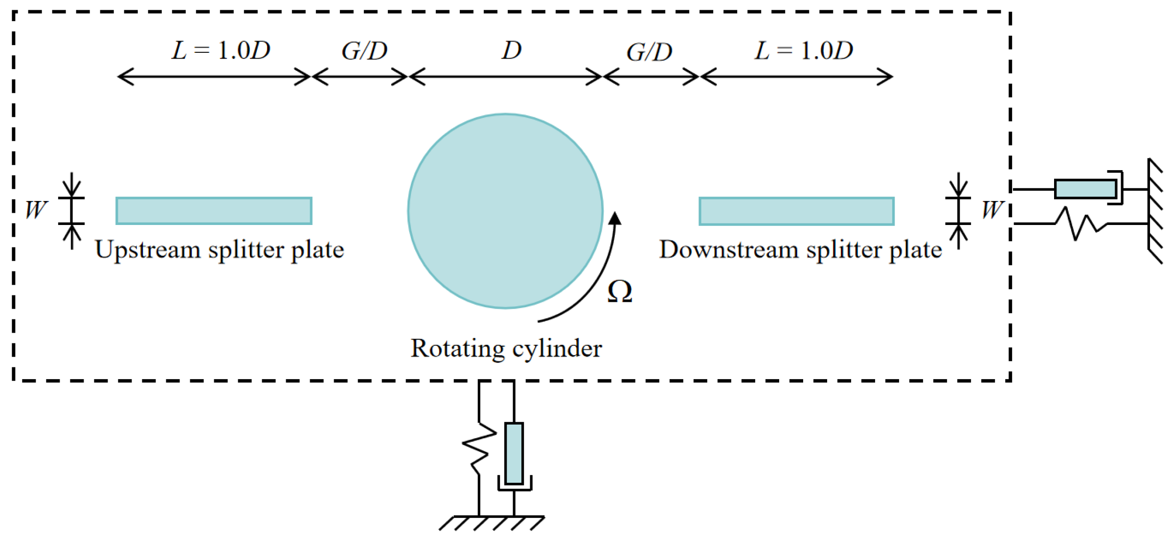
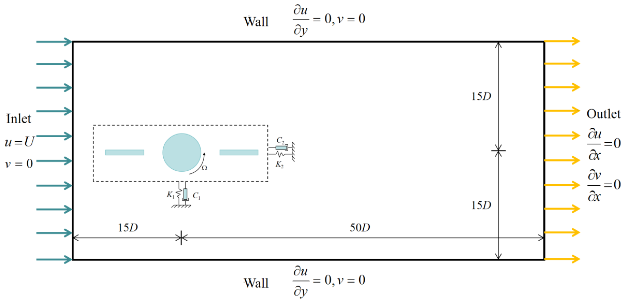
2.1. Problem Description and Computational Model

After reviewing the research on the influence of gap distance on the vortex-induced vibration (VIV) of a fixed circular cylinder plate [37,38], this study considers a constant plate length (L/D = 1) and examines the effects of gap distance (G/D = 0.25–2) and width (W/D = 0.1–0.9) on the VIV of a rotating cylinder ( α = 2). The rotation rate, α , is prescribed. Rotational and translational degrees of freedom are independent of each other. The layout diagram of the cylinder and splitter plates is illustrated in Figure 1; the mechanical model of the splitter plates and the cylinder was treated as an integrated structure, with the splitter plates rigidly attached to the cylinder and vibrating synchronously with the rotating cylinder [36]. In this work, a two-dimensional laminar flow field at a Reynolds number of 200 is considered, with the fluid defined as water. The diameter of the cylinder in the study is D = 0.01 m, and the fluid density is ρ = 998.2 kg/m3. Linear springs and dampers are elastically mounted on the cylinder body in both cross-flow and in-line directions, forming a freely vibrating mass–spring–damper system. The damping ratio (ζ) and mass ratio (m*) of this vibration system are established to 2.6 and 0, respectively, and are characterized by the following definitions: m* = 4m/ρπD2, ζ = c / 2 k m , where m is the mass of the cylinder, c is the damping coefficient, and k is the spring stiffness.
The computational domain and boundary conditions are shown in Figure 2, where the cylinder is located at the origin of the coordinate system. The computational domain extends from 15 D to 50 D in the in-line (x) direction and from 15 D to 15 D in the cross-flow (y) direction [39,40]. The cylinder–plate is connected to two spring–damper systems and is free to vibrate in both the cross-flow and in-line directions. K and C represent the linear elastic spring and damper connected to the cylinder-plate, respectively. K 1 and C 1 combine to form the cross-flow spring–damper system, while K 2 and C 2 combine to form the in-line spring–damper system.
The boundary conditions in the computational domain are set as follows: the left boundary is designated as a velocity inlet boundary condition, where u = U , v = 0 . u and v are the velocities in the in-line direction and cross-flow direction, respectively; the right boundary is set as an outflow condition, where u / x = 0 , v / x = 0 ; the upper and lower boundaries are designated as Neumann boundary conditions, where u / y = 0 , v = 0 ; and the no-slip wall boundary condition is applied to the cylinder, where u ( t ) = d x ( t ) / d t , v ( t ) = d y ( t ) / d t .

2.2. Governing Equations and Numerical Method

The two-dimensional laminar flow past a circular cylinder is governed by the incompressible unsteady Navier–Stokes equations, which are expressed as follows [41,42]:
u = 0 ,
δ u δ t + ( u ) u = 1 ρ p + υ 2 u ,
where u* is the velocity vector in the Cartesian coordinate system (x, y); ρ is the density; and p is the pressure; and υ is kinematic viscosity. The Navier–Stokes equations are discretized using the Finite Volume Discretization Method (FVDM), and the pressure and velocity are coupled using the SIMPLE method. The vibration system of the cylinder is considered a mass–spring–damper system. The controlling equations for the in-line and cross-flow motions of the cylinder are second-order ordinary differential equations [43]:
y ¨ ( t ) + 4 π ζ V r y ˙ ( t ) + 2 π V r 2 y ( t ) = 2 C l π m , x ¨ ( t ) + 4 π ζ V r x ˙ ( t ) + 2 π V r 2 x ( t ) = 2 C d π m ,
where C l = 2 F y / ( ρ U 2 D L ) and C d = 2 F x / ( ρ U 2 D L ) represent the lift and drag coefficients, respectively. U is the uniform incoming fluid velocity. Fy and Fx are the lift and drag forces, respectively. ζ is the damping ratio. The reduced velocity is V r = U / f n D , where the natural frequency is f n = 1 / 2 π k / m . m* is the mass ratio. The non-dimensional displacement, velocity, and acceleration of the cylinder in the cross-flow and in-line directions are denoted as y ( t ) , y ˙ ( t ) , y ¨ ( t ) , x ( t ) , x ˙ ( t ) and x ¨ ( t ) , respectively. The governing equations are solved using the fourth-order Runge–Kutta method. Equation (3) can be represented as follows [44]:
y ( t n + 1 ) = y ( t n ) + t 6 ( K 1 + K 2 + K 3 + K 4 )
y ˙ ( t n + 1 ) = y ˙ ( t n ) + t 6 ( L 1 + 2 L 2 + 2 L 3 + L 4 )
where
K 1 = y ˙ ( t n )
L 1 = F ( t n ) m ω 0 2 y ( t n ) 2 ζ ω 0 y ˙ ( t n )
K 2 = y ˙ ( t n ) + t 2 L 1
L 2 = F ( t n ) m ω 0 2 y ( t n ) + t 2 K 1 2 ζ ω 0 y ˙ ( t n ) y ˙ ( t n ) + t 2 L 1
K 3 = y ˙ ( t n ) + t 2 L 2
L 3 = F ( t n ) m ω 0 2 y ( t n ) + t 2 K 2 2 ζ ω 0 y ˙ ( t n ) y ˙ ( t n ) + t 2 L 2
K 4 = y ˙ ( t n ) + t 2 L 3
L 4 = F ( t n ) m ω 0 2 y ( t n ) + t 2 K 3 2 ζ ω 0 y ˙ ( t n ) y ˙ ( t n ) + t 2 L 3
where K1, K2, K3, K4, L1, L2, L3, and L4 are the fourth-order Runge–Kutta transition functions, the subscript n denotes the number of time steps, t is the time step size, and ω 0 represents the natural frequency of the cylinder, with ω 0 = k / m .
The User-Defined Function (UDF) program can be imported into the software through the UDF interface in Fluent 2022 R1 for simulation calculations. The iterative process of each step for UDF is as follows: (1) Calling the macro Compute_Force_And_Moment to calculate the loads on the cylinder boundary and incorporate the results into Equation (3); (2) Invoking an iterative procedure based on the fourth-order Runge–Kutta method to discretize and solve the structural vibration equations, obtaining the displacement, velocity, and acceleration of the cylinder; (3) Using the macro DEFINE_CG_MOTION to transmit the displacement, velocity, and acceleration parameters to the corresponding cylindrical boundary, and providing the angular velocity of the cylinder boundary through DEFINE_CG_MOTION to achieve the displacement and rotation of the cylinder.

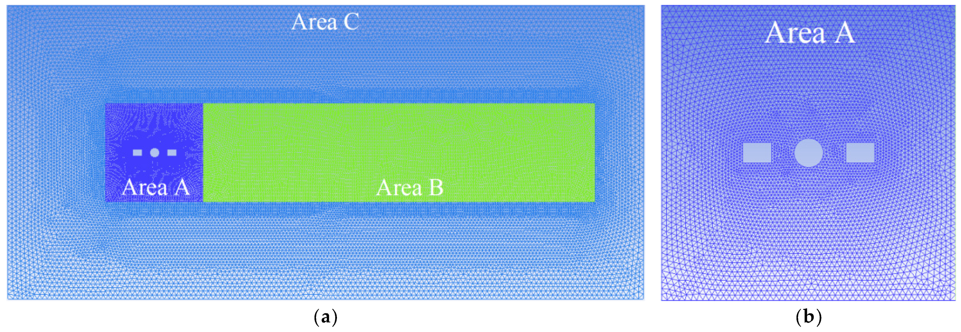
3. Mesh Dependency Study and Validation

As shown in Figure 3, the computational domain is discretized using triangular elements. The computational domain is divided into three parts, namely Regions A, B, and C, where Region A is a dynamic grid region, and Regions B and C are static grid regions. Density of grid elements is higher near the cylinder, which facilitates effective observation, and lower in the wake region.
To validate mesh independence, five meshes with different resolutions (Table 1) are used to simulate flow through a stationary cylinder at a Reynolds number of 200. As the grid size increases from Size I to Size V, where x is defined as the grid size in that region and x / D represents the non-dimensional grid size relative to the cylinder diameter [35]. The results of the calculations are presented in Table 2. The time-averaged drag coefficient (Cd-mean) and Strouhal number (St) obtained for different grid sizes are compared with previous research findings [45]. The computational results indicate that difference percentage is low and, thus, Size III was used to reduce required computational resources.
To further validate the accuracy of the numerical model and method presented in this paper, the amplitude of vortex-induced vibration (VIV) of a rotating cylinder is compared with previous studies. The comparison of cross-flow amplitudes is shown in Figure 4. The relevant computational parameters are R e = 200 , m = 2.6 , and α = 1 . Ay/D and Ax/D represent the non-dimensional amplitudes of the cylinder in the cross-flow and in-line directions, respectively. The amplitude of the cylinder increases first and then decreases. When V r = 5 , the amplitude of the cylinder reaches its peak, and the lock-in region of the cylinder decreases due to the rotation effect. The results indicate that the VIV response of the cylinder matches well with that of Bao et al. [34].
Cross-flow amplitudes of the bare cylinder at different rotation rates are shown in Figure 4. The initial branch, lower branch, and desynchronization branch can be clearly identified [46,47]. Compared to a non-rotating cylinder, the amplitude of the rotating cylinder in the lock-in region is reduced, indicating that rotation has a certain inhibitory effect on vibration. It is noteworthy that the cylinder maintains a high amplitude at V r = 5 (the peak). Therefore, in this study, further discussions are conducted on the vibration suppression of a rotating cylinder with a splitter plate at V r = 5 and α = 2 .

4. Results and Discussion

This section primarily discusses the vibration responses and flow characteristics of cylinders with dual splitter plates and investigates the vibration–hydrodynamic–wake interactions, with a particular focus on the moments when wake patterns change. Additionally, it explores the sensitivity of lift and drag coefficients to G/D and W/D through numerical methods. The main numerical experimental results of this paper are presented in this section.

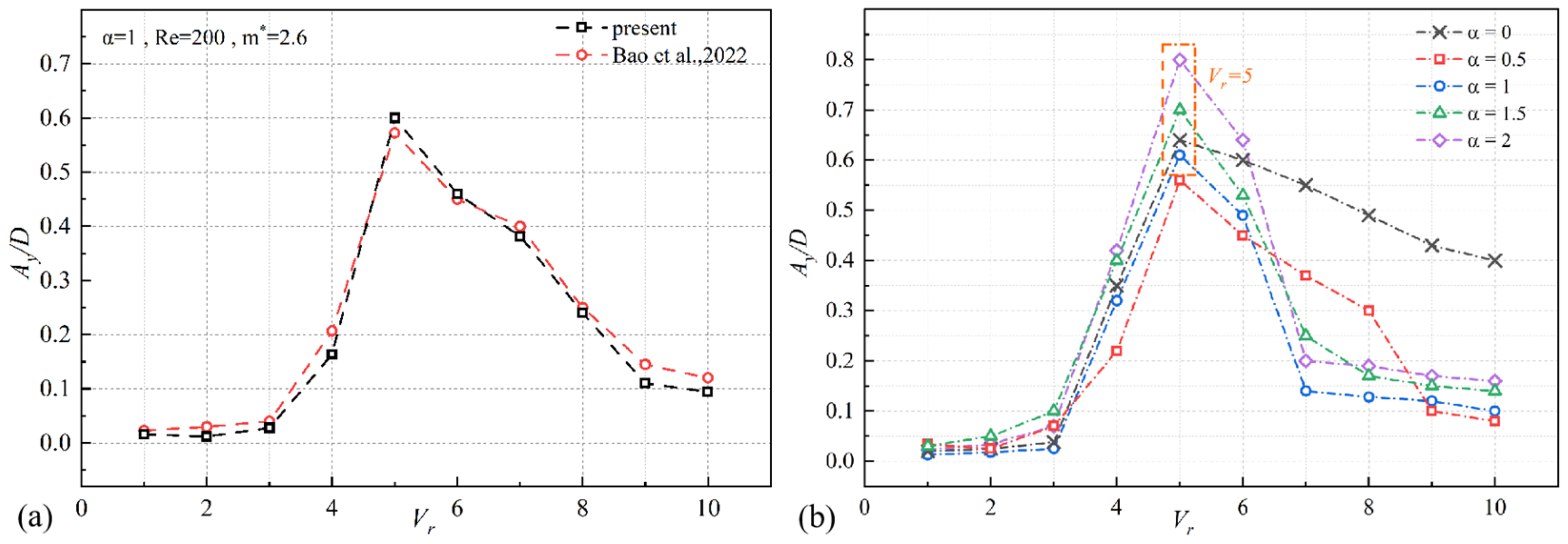
4.1. Response Amplitude

The vibration responses of the cylinder with different widths and gap distances are shown in Figure 5. At low gap distances (G/D = 0.25, 0.5), cross-flow and in-line amplitudes are relatively low, demonstrating effective suppression in both directions. Amplitudes increase as the width (W/D) rises, and the G/D = 0.5 configuration can achieve the best suppression performance; at high gap distances (G/D > 0.5), cross-flow and in-line amplitudes are significantly high. Dual splitter plates exhibit some suppression of cross-flow vibrations, but their effectiveness is limited, with amplitudes even increasing in some cases. Though the cross-flow amplitudes generally show a declining trend with increasing W/D, the cross-flow amplitudes are less sensitive to W/D. In the in-line direction, amplitudes mostly exceed the range of bare rotating cylinders, indicating negligible suppression—a deviation from previous studies reporting effective suppression within specific G/D ranges [36]. The reason is that the high rotation ratio is adopted in this work, which intensifies cylinder vibrations. In the initial phase (W/D = 0.1–0.2), in-line amplitudes are suppressed at G/D = 0.75–1.25. In the intermediate phase (W/D = 0.3–0.7), in-line amplitudes exceed the range of bare cylinders. At different gap distances, in-line amplitudes reach their peaks at varying widths and then decline. In the late phase (W/D = 0.8–0.9), in-line amplitudes decrease at W/D = 0.8 for G/D = 1.75 and 2.0 but sharply rebound to high values at W/D = 0.9, except for G/D = 1.25, where a sharp reduction occurs at W/D = 0.9. Overall, in-line amplitudes at high gap distance first rise and then decline with increasing widths, showing similar trends across configurations.
The Ymean and Xmean of the cylinder at different widths and gap distances are shown in Figure 6. Ymean and Xmean represent the time-averaged nondimensional displacement of the cylinder in the cross-flow and inline directions, respectively. Due to the Magnus effect, when the cylinder rotates counterclockwise, it induces circumferential motion in the surrounding fluid. As a result, the cylinder experiences a transverse force, causing its trajectory to deviate. This deviation is approximately linear.
The trends in displacement variations differ between low gap distances (G/D = 0.25, 0.5) and high gap distances (G/D > 0.5). At low gap distances (G/D = 0.25, 0.5), Ymean decreases with increasing width, G/D = 0.25 provides better suppression of Ymean compared to G/D = 0.5. Ymean changes linearly at G/D = 0.25 and G/D = 0.5, but Ymean at G/D = 0.5 is significantly higher due to the greater lift coefficient. At G/D = 0.75, the lift value increases sharply when W/D = 0.7, resulting in large Ymean as well. The Ymean shows a decreasing trend at high gap distances, though a rebound increase occurs at certain widths. Additionally, G/D = 0.25 and 1.0 maintain effective suppression of the Ymean, with suppression performance improving as width increases. For the gap distance G/D = 0.75, the Ymean exhibits a significant change at W/D = 0.7. For the gap distances G/D = 1.75 and 2.0, the Ymean shows a significant change at W/D = 0.8. These observations are consistent with the variations in amplitudes. The Xmean decreases with increasing width, and its direction reverses. The Xmean varies linearly with width, and Xmean is significantly smaller than the Ymean. At low gap distances (G/D = 0.25, 0.5), Xmean varies slightly. At high gap distances (G/D > 0.5), specific width values can be selected to achieve the Xmean of 0.

4.2. Hydrodynamics Coefficients

The root mean square of the lift coefficients, Cl-RMS, and the time-averaged drag coefficients, Cd-mean, are shown in Figure 7. It can be observed that width exerts a notable suppression influence on Cl-RMS and Cd-mean. For cases with low gap distances (G/D = 0.25, 0.5), Cl-RMS and Cd-mean show a linear relationship with the width. Cd-mean is effectively suppressed, decreasing slowly with an increase in the width. Cl-RMS is notably reduced under the condition of G/D = 0.25, both Cl-RMS and Cd-mean hit their minimums at W/D = 0.9. For high gap distances (G/D > 0.5), at small widths (W/D = 0.1–0.5), Cl-RMS shows little difference across various gap distances. However, at larger widths (W/D = 0.6–0.9), distinctions become apparent among different gap distances. Cd-mean shows a more pronounced change with an increase in the width. In the range of W/D = 0.1–0.6, a lower gap distance results in lower Cd-mean values, indicating strong drag reduction effects. Specifically, for G/D = 1.75 and 2.0, there is a sharp decrease at widths of W/D = 0.7 and 0.8, respectively, demonstrating the effectiveness of the width in suppressing the drag coefficient.
Variations in hydrodynamic coefficients can induce corresponding alterations in amplitude. Lift coefficient is proportional to cross-flow amplitude. Combining the observations from the amplitude curve (Figure 5), it is evident that the relationship between Cl-RMS and the cross-flow amplitude is not a simple relationship. Taking the case of gap distance G/D = 2.0 with widths W/D = 0.1 and 0.2 as examples, it is observed that as Cl-RMS decreases, the cross-flow amplitude actually increases. This phenomenon is related to the magnitude of Cl; when Cl-RMS decreases, the fluctuation range of Cl changes, leading to an increase in the extremum, which also causes an increase in the cross-flow amplitude. The decrease in Cl-RMS brings the Ymean closer to their initial equilibrium position. These interactions will be discussed in detail in the chapter Vibration–Hydrodynamic–Wake Interaction.
The time histories of hydrodynamic coefficients at different widths and gap distances are shown in Figure 8. There is a certain phase difference between the oscillations of the lift coefficient and drag coefficient of the cylinder. For dual splitter plates with different gap distances, the hydrodynamic coefficients exhibit stable oscillations at gap distances of G/D = 0.25 and 1.0, while at G/D = 1.5 and 2.0, the oscillations become unstable but still show distinct periodicity. Comparing different gap distances, the amplitude of the hydrodynamic coefficient changes, increasing with the increase in gap distance, whereas the period remains almost unaffected by the gap distance. The increase in gap distance reduces the stability of the oscillation. When comparing different widths, at low gap distances, the amplitude of lift and drag coefficient increases with the increase in width, and the phase also changes with an increase in width. At high gap distances, the effect of width on the amplitude and period of lift and drag coefficient is minimal, affecting only the phase. Periodic variations can be observed under these conditions. Specifically, as the gap distance increases, the instability of oscillation becomes more pronounced, while the influence of width is mainly reflected in the phase variation at high gap distances, with little impact on the amplitude or period.
The drag coefficient always exhibits sinusoidal oscillations, whereas the lift coefficients do not display such behaviors. As shown in Figure 8a, both the lift and drag coefficients follow a sinusoidal curve; in Figure 8b, it is illustrated that at W/D = 0.9, the lift coefficients display non-sinusoidal oscillations; in Figure 8c, the non-sinusoidal oscillations exhibits at W/D = 0.7 and 0.9, and similar phenomena are observed in Figure 8d. From these observations, it can be concluded that the lift coefficient shows sinusoidal oscillations at low gap distances and non-sinusoidal oscillations at high gap distances with high widths; the drag coefficient always follows a sinusoidal curve. These highlight the influence of gap distance and width on the nature of the oscillations of lift and drag coefficients.

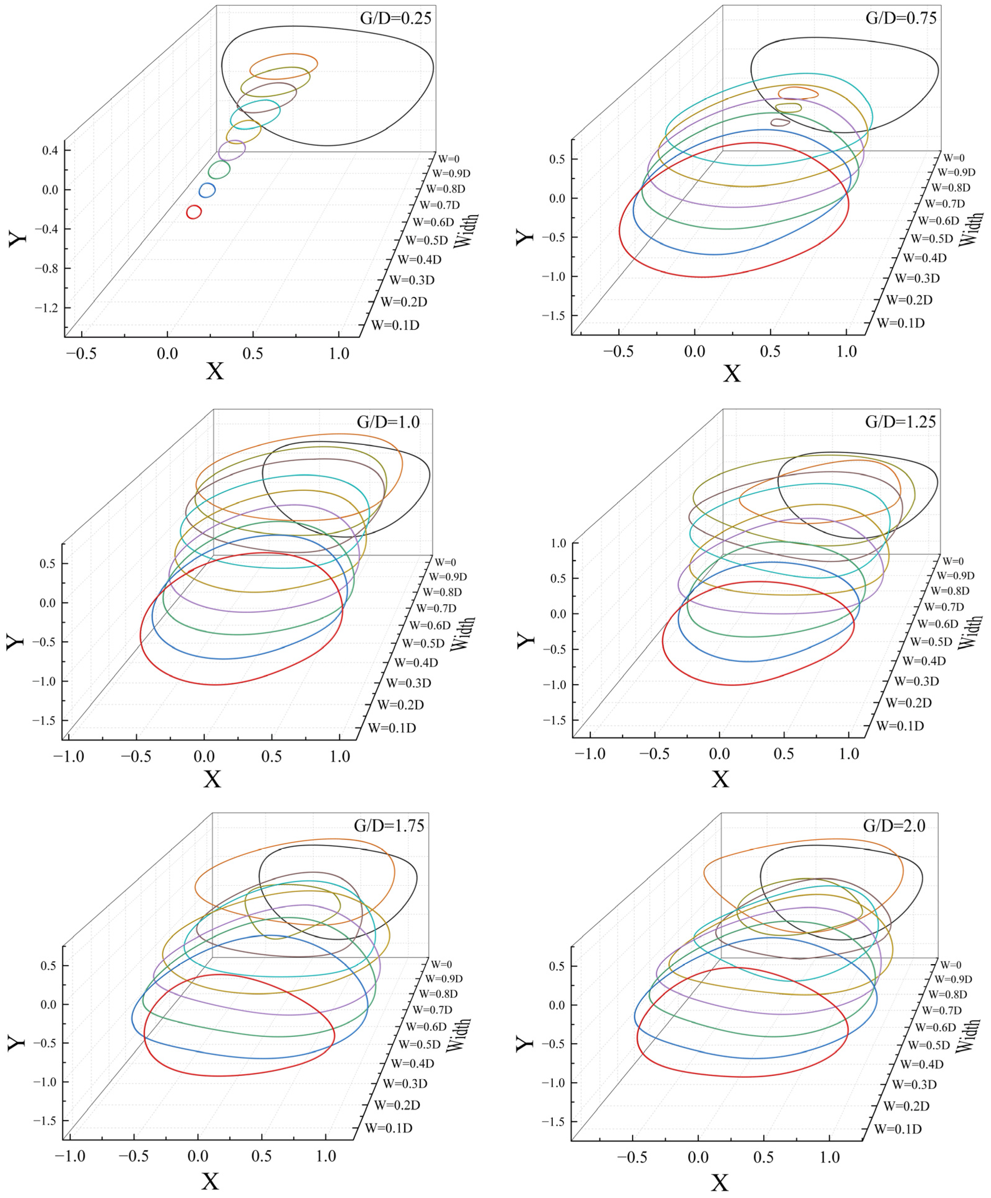
4.3. Cylindrical Vibration Trajectory
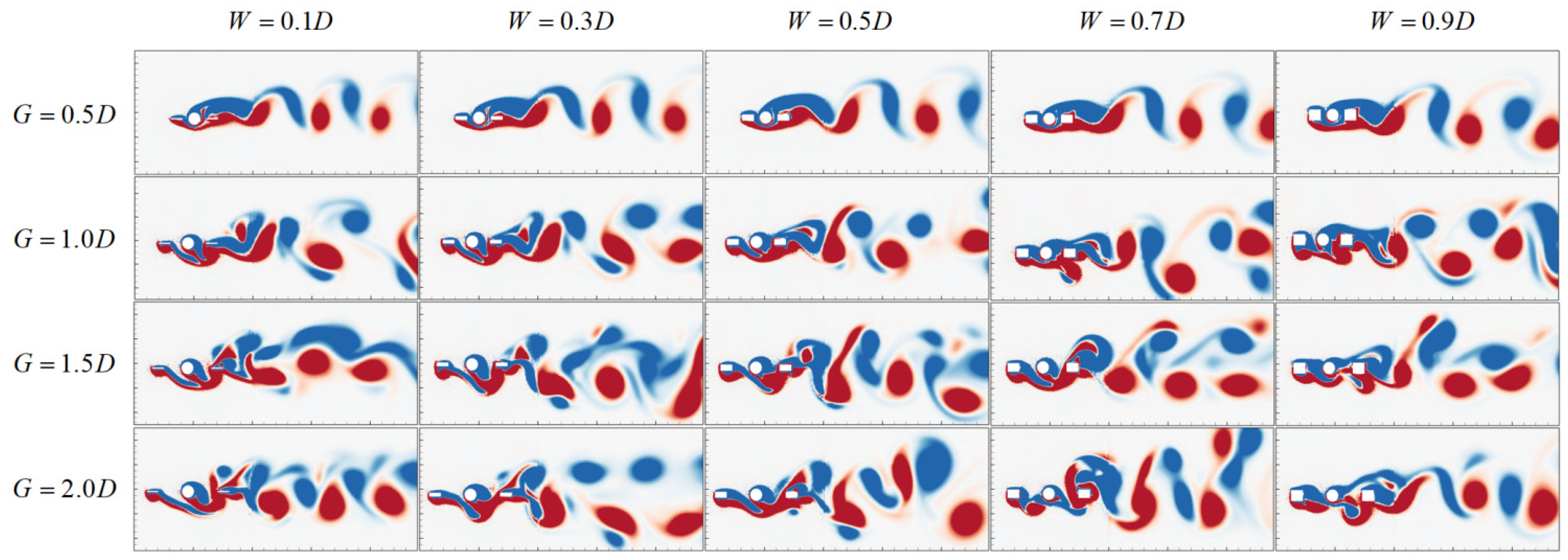
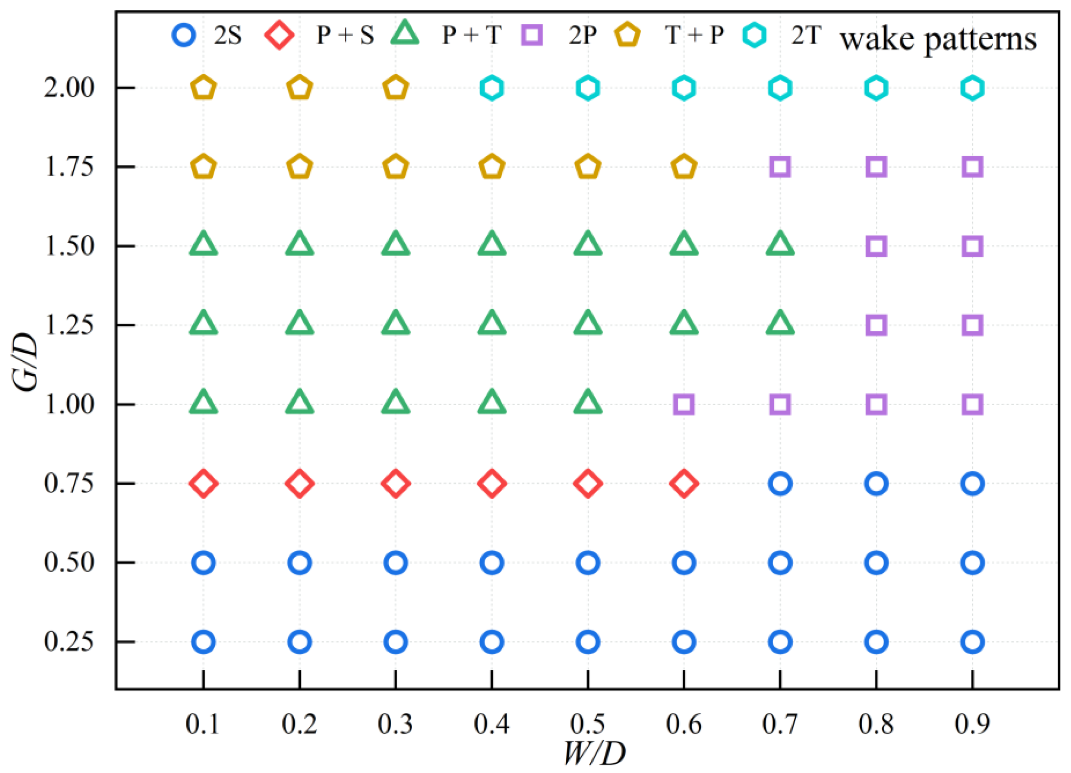
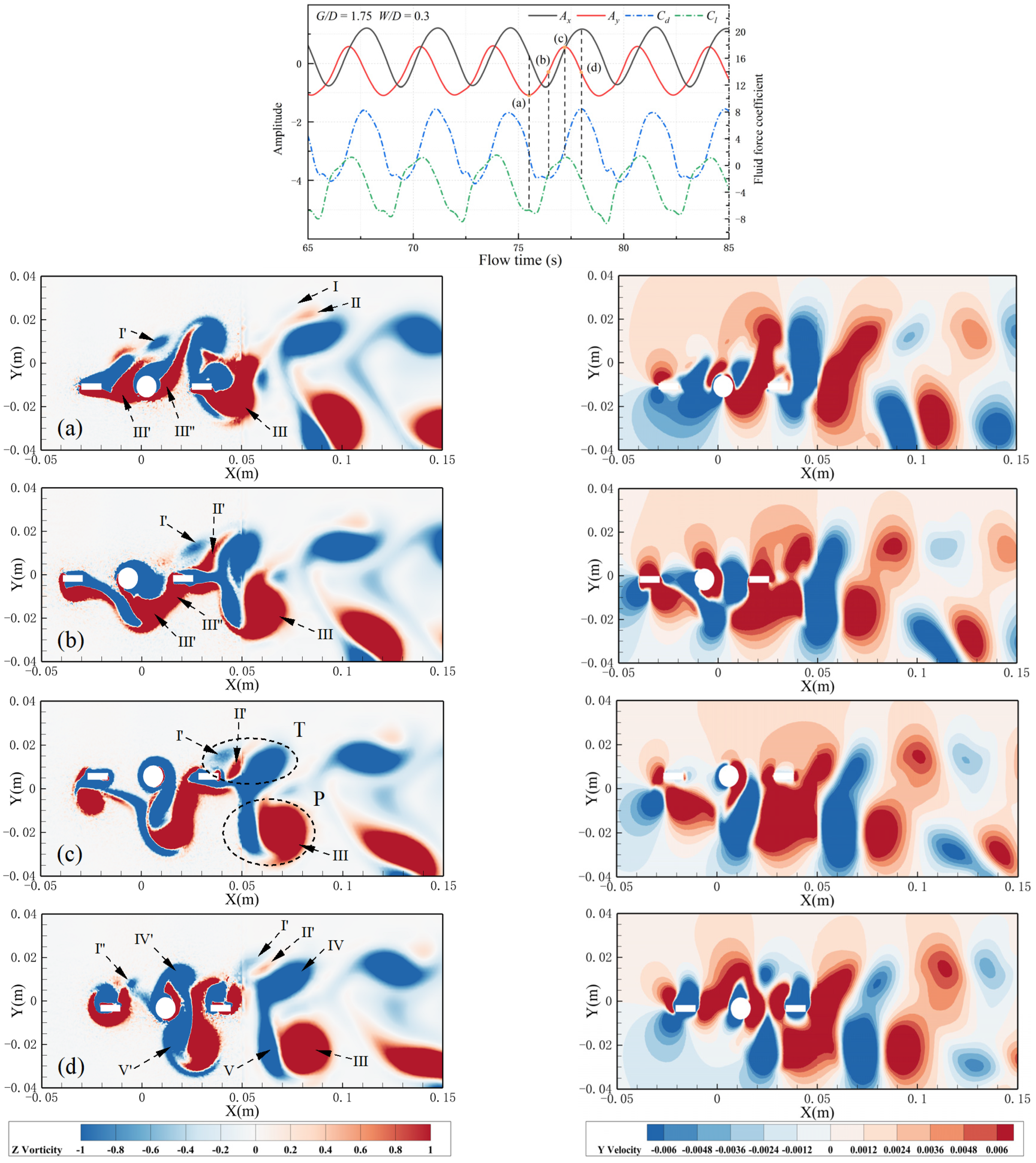
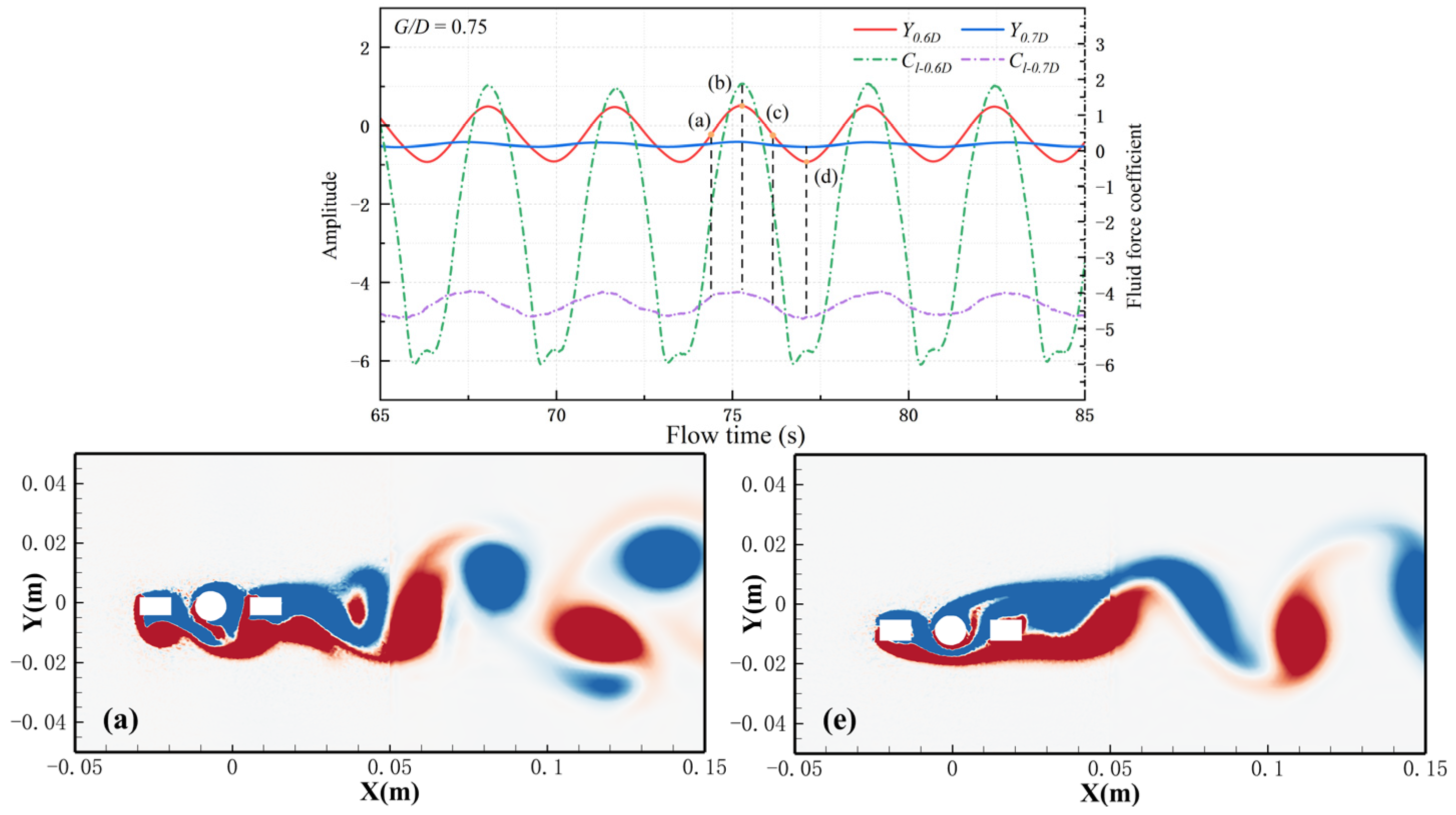
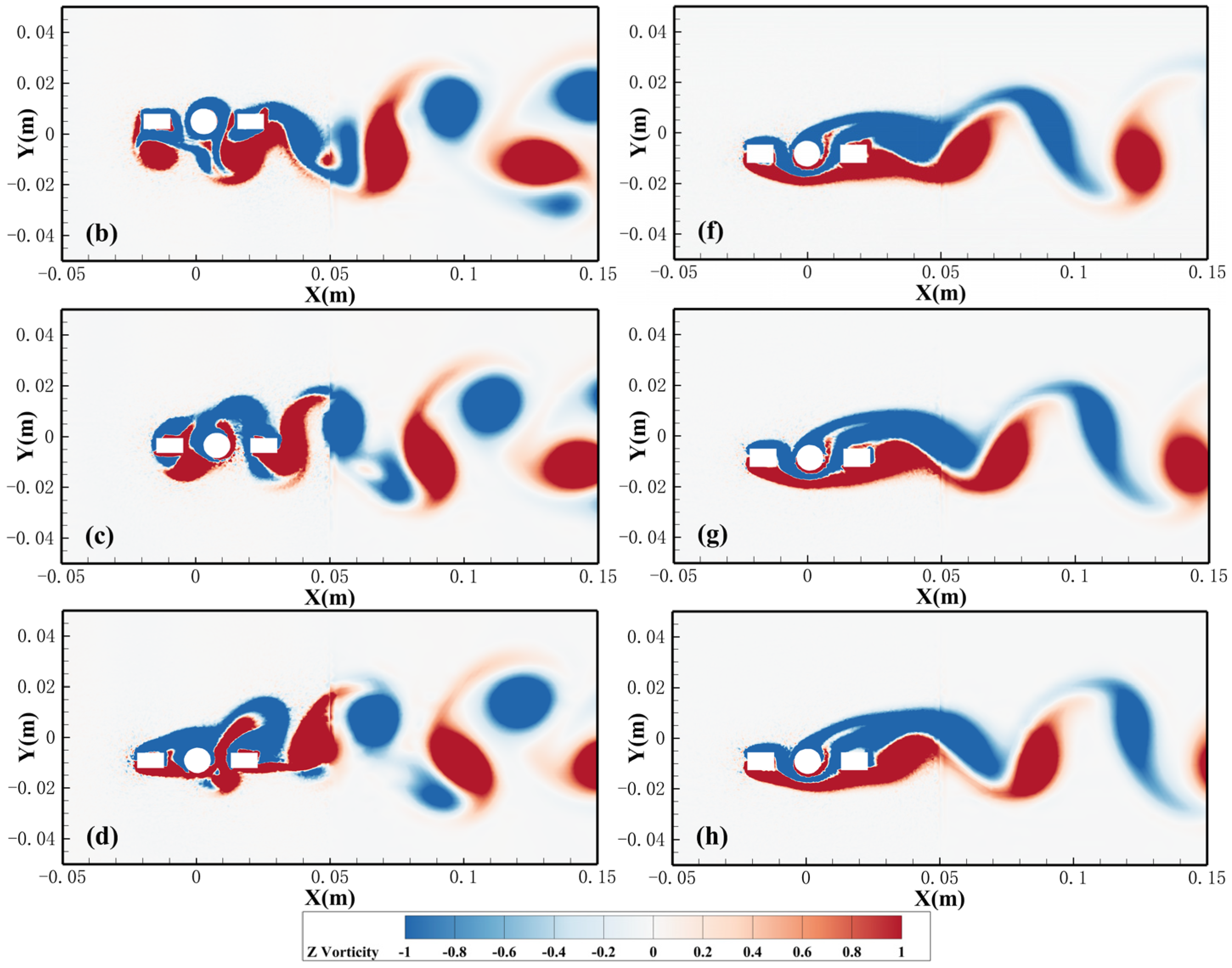
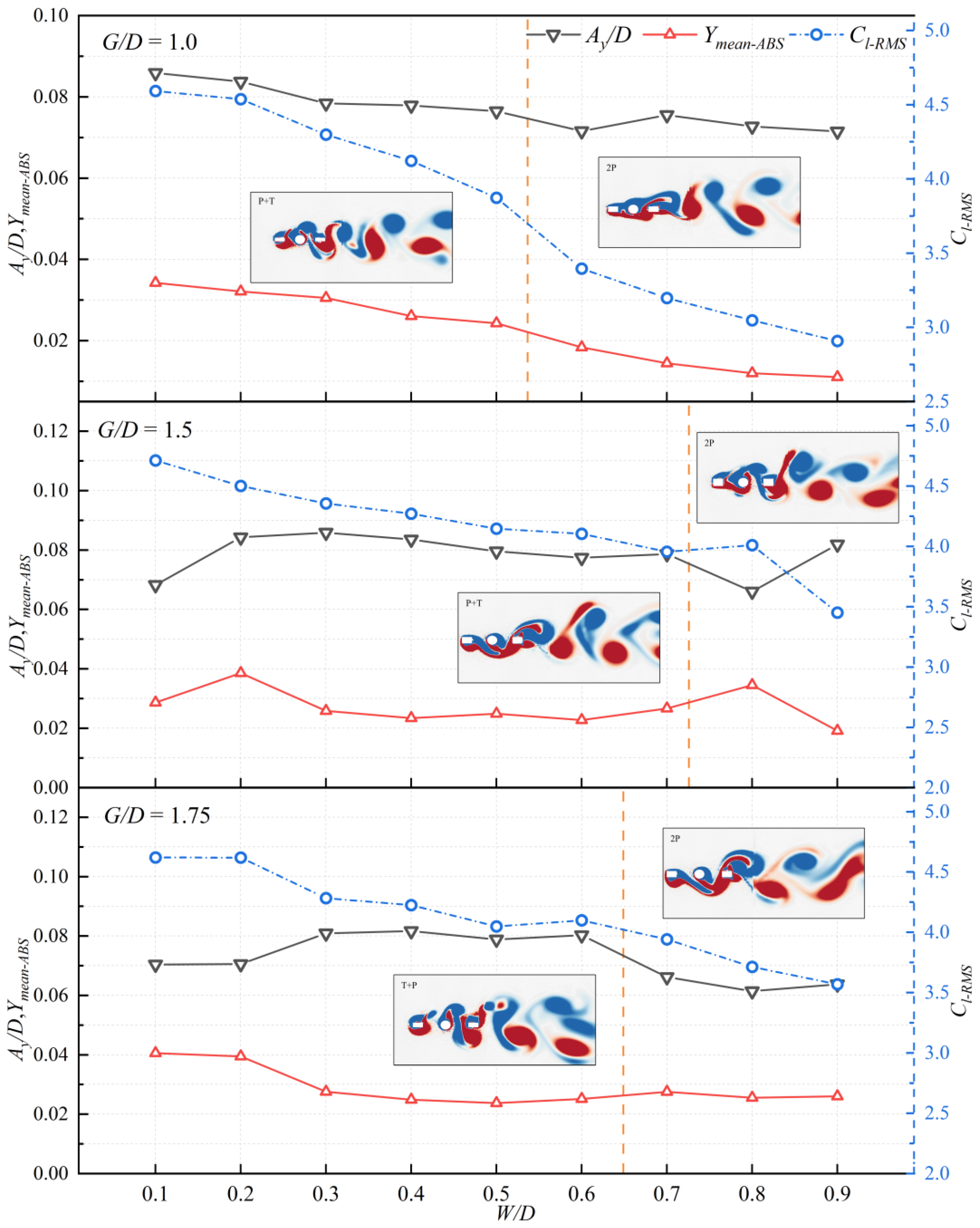
The vibration trajectories of the bare cylinder and the cylinder with dual splitter plates at different gap distances and widths are shown in Figure 9. For a bare cylinder, there is a certain phase difference between the cross-flow direction and the in-line direction vibrations, with the cross-flow frequency being roughly the same as the in-line frequency, resulting in a roughly circular motion trajectory.
At a gap distance of 0.25, the presence of dual splitter plates significantly reduces the area of the vibration trajectory, with the trajectory decreasing as the width decreases and remaining at a consistently low level. As the gap distance increases, the cross-flow amplitude gradually increases while the in-line amplitude decreases, causing the vibration trajectory to transform into a flatter elliptical shape. The area of the vibration trajectory increases with the gap distance, indicating that the suppression effect on the vibration trajectory diminishes. Similar results can be observed from the amplitude curves.
When the gap distances are 0.25, 0.75, and 1.0, the shapes of the cylinder vibration trajectories under different widths are similar, but as the width increases, the vibration trajectory shifts towards the upper left, moving in a direction opposite to the cylinder’s rotation. Specifically, when the gap distance is 0.75, at widths of 0.7, 0.8, and 0.9, the vibration trajectory significantly decreases, reaching its lowest value at widths of 0.7, which is attributed to an increase in lift coefficient and a substantial decrease in drag coefficient based on force analysis. For gap distances of 1.25, 1.75, and 2.0, cylinder vibrations intensify, and the trajectories among different widths become irregular. Under certain conditions, the trajectory area can be effectively suppressed; for instance, at a gap distance of 1.75 with a width of 0.8, or at a gap distance of 2.0 with a width of 0.8.

4.4. Wake Pattern

Figure 10 shows the instantaneous vorticity contours of a cylinder moving towards its equilibrium position in the cross-flow direction. For rotating cylinders, at low gap distances (G/D = 0.25, 0.5), the wake pattern is of the 2S pattern. The 2S pattern refers to the alternating shedding of positive and negative vortices. As the gap distance increases to 1.0, the 2S pattern disappears and the wake pattern transitions primarily to 2P and P+S patterns, with an increase in the number of vortex shedding at the same time. When the gap distance increases, the periodicity of vortex shedding decreases, and it can be clearly observed that the distance between positive and negative vortices becomes smaller, with vortex shedding rapidly downstream of the cylinder. At the same width, the position of the positive vortex shedding from the cylinder at its equilibrium position moves rearward as the gap distance increases. This phenomenon is especially evident at widths of 0.7 and 0.9.
The wake pattern map with different gap distances and widths is shown in Figure 11. Changes in gap distance and width lead to variations in the wake flow patterns. At a fixed gap distance, an increase in width results in transformations of the wake flow pattern. At low gap distances (G/D = 0.25, 0.5), the vortex shedding pattern is a stable 2S pattern. At G/D = 0.75, a significant change in the vortex shedding pattern occurs at W/D = 0.7, transitioning from a P+S pattern to a 2S pattern. For other gap distances (G/D = 1.0–2.0), due to the large number of vortices shedding, the shedding pattern becomes unstable. Specifically, at G/D = 1.25 and W/D = 0.7, the vortex shedding pattern is P+T, leading to velocity differences among vortices in the wake region. Vortices shed later may intersect with those shed earlier in the wake region, causing scenarios where vortices shed at different times synchronize their motion, making the vortex shedding behavior more complex. When the W/D reaches 0.8, the vortex shedding pattern gradually changes to a 2P pattern.
At a gap distance of G/D = 1.5, an increase in width leads to a more stable vortex shedding pattern. A notable phenomenon of vortice merging occurs; for example, at W/D = 0.5, due to the presence of the gap, negative vortices shed from the front side of the downstream plate are complete and fully developed, affecting the vortex shedding from the cylinder. The presence of the downstream plate restricts the development of vortices from the cylinder, causing one negative vortice to shed from each side of the cylinder. The negative vortice shed from above the cylinder does not merge with the negative vortice shed from the upper front side of the downstream plate during shedding. In the rear wake region, velocity differences between vortices cause them to move closer together and be influenced by the vortice force field, transforming the shape of the vortices from circular to flattened. The positive vortice shed from the upper surface of the cylinder moves towards the downstream plate and splits into two positive vortices, which then shed separately from the upper and lower sides of the downstream plate.
The small positive vortice shed from the upper side gradually dissipates, while the large positive vortice shed from the lower side merges with another positive vortice shed from the downstream plate’s back side, forming a larger positive vortice that continues moving backward. vortices shed from the front side of the upstream plate primarily merge with the lower positive vortice.
Due to the influence of rotation, a negative vortice forms on the upper side of the upstream plate and sheds from below the cylinder, merging with the negative vortice shed from below the cylinder. This elongates the vortice shape. At the front side of the downstream plate, this merged negative vortice splits into two negative vortices, shedding separately from the upper and lower sides. Part of the upper negative vortice merges with the negative vortice shed from the upper side of the cylinder, forming a P pattern with the upper positive vortice, while the lower negative vortices form a T pattern with the lower positive vortice. As the vortices continue to develop, differences in force fields, velocities, and trajectories among multiple vortices lead to lagging or leading phenomena. The disappearance of vortices and their interactions further complicate and destabilize the vortex shedding behavior.
This paper introduces a special T+P vortex shedding pattern. At a gap distance of 1.75D, as the width increases, the T+P pattern gradually transforms into a 2P pattern, with one negative vortice disappearing from the upper side of the downstream plate. At a gap distance of 2.0D, as the width increases, the vortex shedding pattern transitions gradually from T+P to 2P, with an increase in the number of shedding vortices. Analyzing the positive vortices, at a width of W/D = 0.3, a rotating cylinder sheds one small positive vortice from above, which disappears shortly after. Another positive vortice sheds from below the cylinder, merges with the positive vortice shed from the upstream plate and then merges again with the positive vortice on the lower side of the downstream plate, briefly attaching to the lower side of the downstream plate before detaching. At a width of W/D = 0.4, the positive vortice shed from above the cylinder is large and persists, while the positive vortice shed from below does not merge with the positive vortice shed from the upstream plate nor with the positive vortice on the upper side of the downstream plate. Instead, multiple positive vortices form on the back side of the downstream plate.

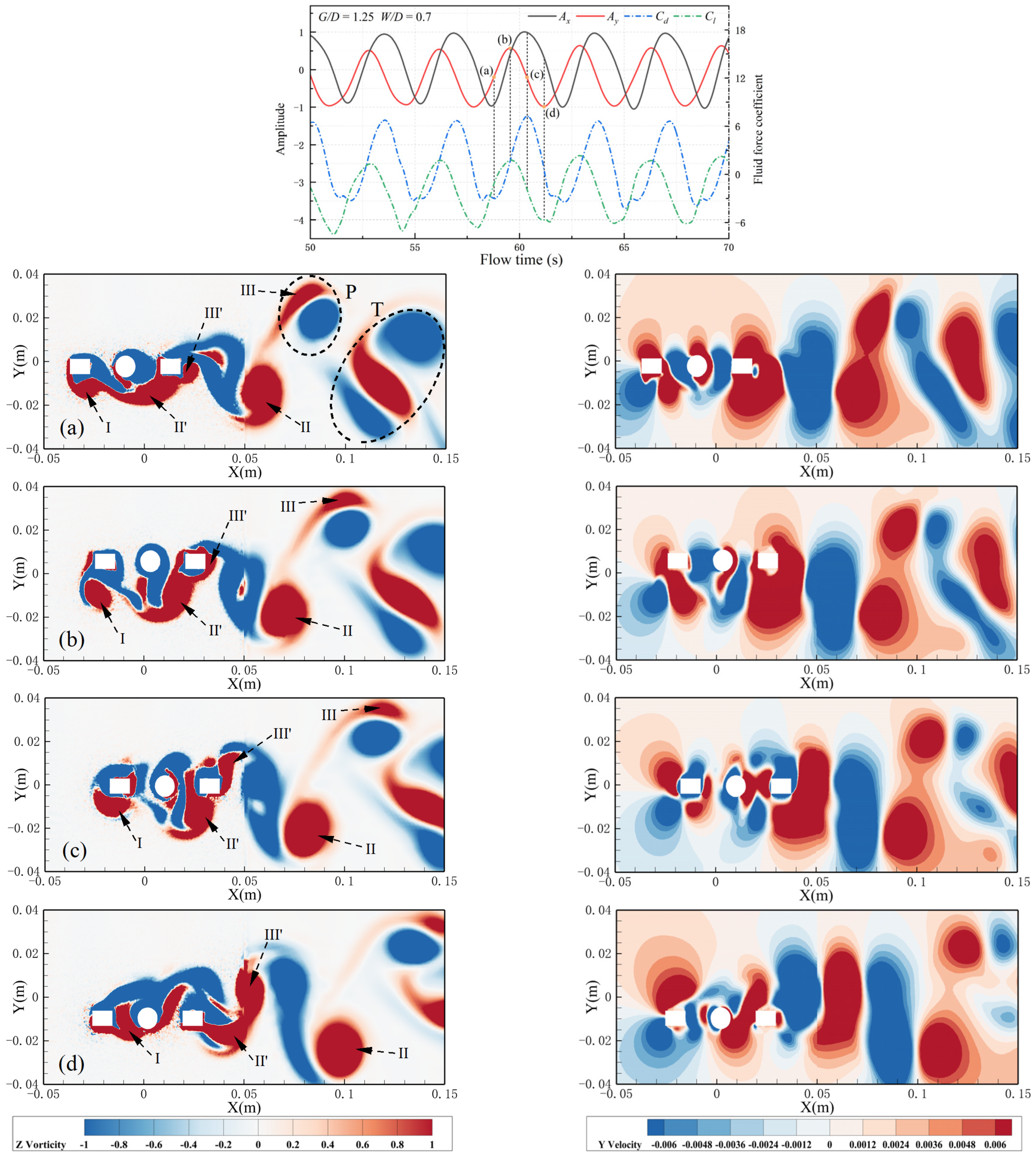
4.5. Vibration–Hydrodynamic–Wake Interactions

To further understand the wake patterns under different design parameters of dual splitter plates, the coupling effects of cylinder vibration and hydrodynamic forces, as well as the evolution of wake structures in three typical wake patterns, were analyzed. The time histories of cylinder vibration and hydrodynamic forces, along with vorticity and velocity contour plots, are shown in Figures below: Figure 12 (2S pattern), Figure 13 (P+T pattern), and Figure 14 (T + P pattern). The 2S pattern maintains low cross-flow amplitudes, whereas the P + T and T + P patterns exhibit high amplitudes.
The evolution of the 2S pattern is illustrated in Figure 12, where both in-line and cross-flow vibrations and hydrodynamic force coefficients show sinusoidal oscillations. The in-line amplitude is roughly equal to the cross-flow amplitude, leading to a circular trajectory for the cylinder (Figure 9), with lift and drag coefficients amplitudes being approximately equal. As the incoming flow passes through the upstream plate, the vortice layer separates and merges with the vortice layer detaching from below the cylinder. At this point, the cross-flow velocity below the cylinder is relatively low. As shown in Figure 12a, the cylinder moves upward from its lowest point. When it reaches the equilibrium position, the symmetry of the flow is disrupted due to the rotation of the cylinder. A small amount of the vortice layer attaches to the upper side of the downstream plate, and the cross-flow velocity reaches its peak. Due to the influence of the width, the vortice layer on the upper side of the downstream plate merges with the lower vortice layer from the rear, causing positive vortices to cover the surface of the downstream plate. As the cylinder moves from its highest point (Figure 12c) to the equilibrium position (Figure 12d), the vortice layer within the gap between the cylinder and the downstream plate tends to decay, and the cross-flow velocity once again reaches its peak. Within one cycle, a pair of positive and negative vortices decay downstream, displaying the characteristic 2S wake pattern.
At a gap distance of G/D = 1.25 and width W/D = 0.7, the P+T wake pattern is observed (Figure 13). At the equilibrium position of motion (Figure 13a), the vortex shedding from the upstream plate does not merge with that from the cylinder; instead, the vortex shedding from the upstream plate occurs earlier, resulting in an independent positive vortex shedding from the lower side of the upstream plate. As shown in Figure 13b, vortice I has fully formed and detached from the upstream plate. Due to the high gap distance, positive vortices shed from both the front and rear sides of the cylinder, making the vortex shedding process complex. Vortice Ι Ι reattaches to the downstream plate, with peak cross-flow velocities alternating. Vortices on the lower side of the downstream plate alternately attach, frequently merging and splitting, leading to an asymmetric pressure distribution, which results in a significant lift coefficient. In the latter half of the cycle, similar attachment behavior of negative vortices can be observed on the upper side of the downstream plate.
Therefore, during each cycle, the angle of attack for the incoming flow passing through the downstream plate continuously changes, a larger angle of attack makes the vortices less likely to attach to the downstream splitter plate and more prone to deviate from the equilibrium position, leading to high amplitudes. Additionally, from the time-averaged histories of vibration and hydrodynamic forces, it is evident that the cross-flow amplitude and lift coefficient are essentially in phase, as are the in-line amplitude and drag coefficient. This aligns with the conclusion that hydrodynamic forces with the same phase as the cylinder generally exhibit high amplitudes [48].
At a gap distance of G/D = 1.75 and width W/D = 0.3, the T+P wake pattern is observed (Figure 14). The vortex shedding between the upstream plate and the cylinder shows similar characteristics. In the downstream gap, vortices shed from the cylinder travel a considerable distance before merging with those from the downstream flat plate; there is no significant merging on the surface of the downstream plate but rather at its rear side after shedding. As shown in Figure 14a,b, the vortices in the gap do not shed from above the cylinder due to its rotation and instead merge with the rear-side vortices of the cylinder, forming a large vortice in the downstream gap. At this point, the peak in-line velocity shifts from the downstream gap towards the downstream plate. Alternating vortices formed in the gap cause the downstream plate to experience alternating peak velocities, leading to an increase in hydrodynamic forces and consequently high amplitudes.
For the latter half of the cycle (Figure 14c,d), one independent negative vortice shed from the front side of the upstream plate meets a positive vortice shed from the upper side of the downstream plate. Both vortices have relatively small circulations. These two vortices, along with the negative vortice shed from the cylinder, form a T pattern. On the lower side of the downstream plate, a pair of positive and negative vortices are formed, leading to an uneven distribution of vortex shedding on both sides of the cylinder. This particular shedding pattern is defined as the T+P pattern.
At G/D = 1.75, when the width (W/D) increases to 0.6, the upstream plate no longer sheds a single independent negative vortice, causing the wake pattern to transition into a 2P pattern. This demonstrates the influence of the width on the vortex shedding pattern. The final results indicate that within the downstream gap, alternating vortice formations lead to different numbers of vortices shedding within the wake, further amplifying the vibration response of the cylinder.
The change in wake patterns typically leads to changes in hydrodynamic forces, which in turn affect the vibration response of the cylinder [49]. As mentioned previously, at a gap distance of G/D = 0.75, when the width increases from 0.6 to 0.7, there is a change in the vortex shedding pattern, with both the in-line and cross-flow amplitudes sharply decreasing from a high-amplitude region to a low-amplitude region. The cross-flow amplitudes and lift coefficients for G/D = 0.75 with W/D = 0.6 and W/D = 0.7 are shown in Figure 15.
As shown in Figure 15a, when the cylinder reaches its equilibrium position, it can be observed that at W/D = 0.6, one vortice attaches to the upstream plate, and two vortices attach to the downstream plate. These vortices detach as the cylinder moves, and the two vortices on the downstream plate merge. At W/D = 0.7 (Figure 15e), a thick vortice layer covers from the front side of the upstream plate to the rear side of the downstream plate without any independent vortices detaching. This phenomenon is due to the increased thickness of the plates causing the merging of vortice layers between the upstream and downstream plates, thereby confining the positive vortices shed from the cylinder within these layers.
Figure 15b illustrates the moment when the lift force reaches its extreme value. Vortices are observed to detach and merge, whereas at W/D = 0.7 (Figure 15f), a single negative vortice detaches from the rear side of the downstream plate. It is evident from Figure 15b that the lift coefficient varies significantly and even reverses direction, leading to large cross-flow vibrations. In contrast, at W/D = 0.7, the lift coefficient values are high but vary within a small range, resulting in the cross-flow amplitude approaching a straight line.
This paper extends analysis to configurations where the gap distance is 1.0, 1.5, and 1.75, focusing on the cross-flow amplitude, the cross-flow mean displacement, the root mean square of the lift coefficient, and vortex shedding patterns for a rotating cylinder under these conditions (Figure 16). For G/D = 1.0, when the width increases from 0.5 to 0.6, the vortex shedding pattern transitions from P+T pattern to 2P pattern resulting in a decrease in Cl-RMS along with reductions in both the absolute value of Ymean and Ay/D, suggesting that the alteration in vortex shedding pattern significantly influences hydrodynamic forces and consequently affects the vibration of the cylinder; for G/D = 1.5, as the width changes from 0.7 to 0.8, there is a transformation from the P + T vortex shedding pattern to the 2P pattern leading to an increase in Cl-RMS while causing a decrease in Ay/D, with the absolute value of Ymean rising, which can be attributed to an increase in lift coefficient but with a reduced range of fluctuation in lift coefficient; for G/D = 1.75, upon increasing the width from 0.6 to 0.7, the vortex shedding pattern shifts from T+P pattern to 2P pattern resulting in a decline in Cl-RMS and Ay/D with the absolute value of Ymean remaining almost unchanged, indicating a reduction in lift coefficient coupled with a small fluctuation range in lift coefficient. These illustrate how subtle changes in vortex shedding patterns can influence hydrodynamic forces and structural responses.

4.6. Lift and Drag Force Sensitivity

The distribution ranges of hydrodynamics coefficients under different gap distances is shown in Figure 17. With changes in gap distance, the mean values of each data group (except for G/D = 0.25) do not differ significantly. Specifically, at G/D = 1.0, the mean value is 3.77, while at G/D = 2.0, it increases to 4.17, with a range difference of 0.4. This indicates that, for G/D greater than 0.25, the lift coefficient is generally sensitive to changes in the width but not particularly sensitive to changes in the gap distance. From Figure 17b, when the gap distance is 0.25 and 0.5, the distribution range of drag coefficient is small and uniform, when gap distance is greater than 0.5, the distribution range of drag coefficient becomes larger and more scattered, with slightly more points above the mean value than below it. As the gap distance increases, the mean value of each dataset also increases, indicating that at G/D of 0.25 and 0.5, the drag coefficient is not sensitive to changes in the width, whereas when G/D is greater than 0.5, the drag coefficient becomes sensitive to the width.
The distribution ranges of hydrodynamics coefficients under different widths at Vr = 5 and α = 2 are shown in Figure 18. The mean value of Cl-RMS decreases as the width increases. Each data group exhibits its minimum value at a gap distance of 0.25. Excluding these minimum values, within each width category, the Cl-RMS values are uniformly and closely distributed, reinforcing the same conclusion shown in Figure 17a. From Figure 18b, when W/D = 0.1, the mean value is 1.98, at W/D = 0.5, the mean value is 1.49, a decrease of only 0.49, when W/D = 0.9, the mean value drops to 0.22, compared to W/D = 0.5, it decreases by 1.27. The mean value and the range of Cd-mean decreases as the width increases and decreases at an increasing rate. The study of the sensitivity of the lift and drag coefficients to the gap distances and widths will help in reducing cylindrical forces by making parameter adjustments as needed in engineering practice.

5. Conclusions

At a low Reynolds number of 200, numerical model and computational grid were established. Numerical simulations are conducted on a rotating cylinder with dual splitter plates, with gap distance (G/D) ranging from 0.25 to 2 and width (W/D) ranging from 0.1 to 0.9, at a reduced velocity Vr = 5 and rotation rate α = 2 by using the UDF window in Fluent 2022 R1 software. The two-dimensional laminar flow past a circular cylinder is governed by the incompressible unsteady Navier–Stokes equations. This study could model the vortex-induced vibration caused by marine drilling under wave impact conditions. The results and discussions mainly focus on amplitude suppression of the rotating cylinder, evolution of wake patterns, and the impact of lift and drag sensitivity. The design parameters for gap distance and width of dual splitter plates are summarized based on these findings. The main results are summarized as follows:
(1)
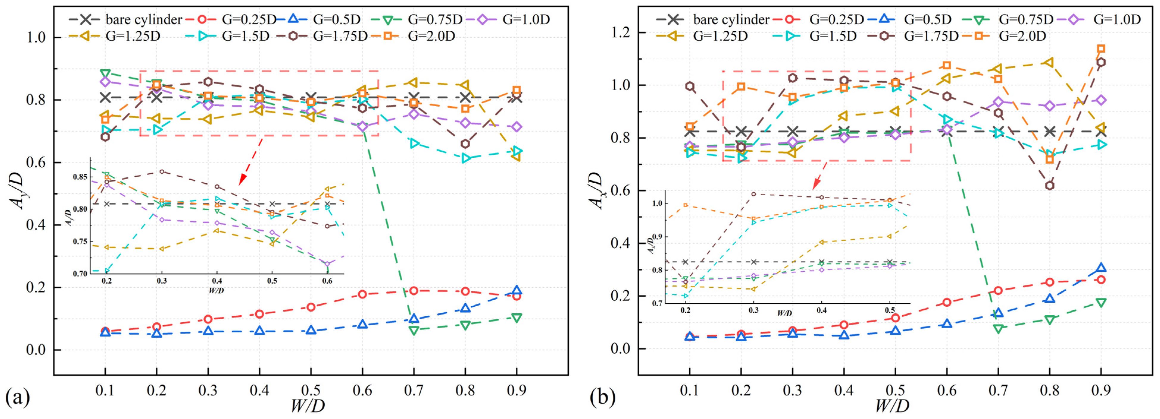
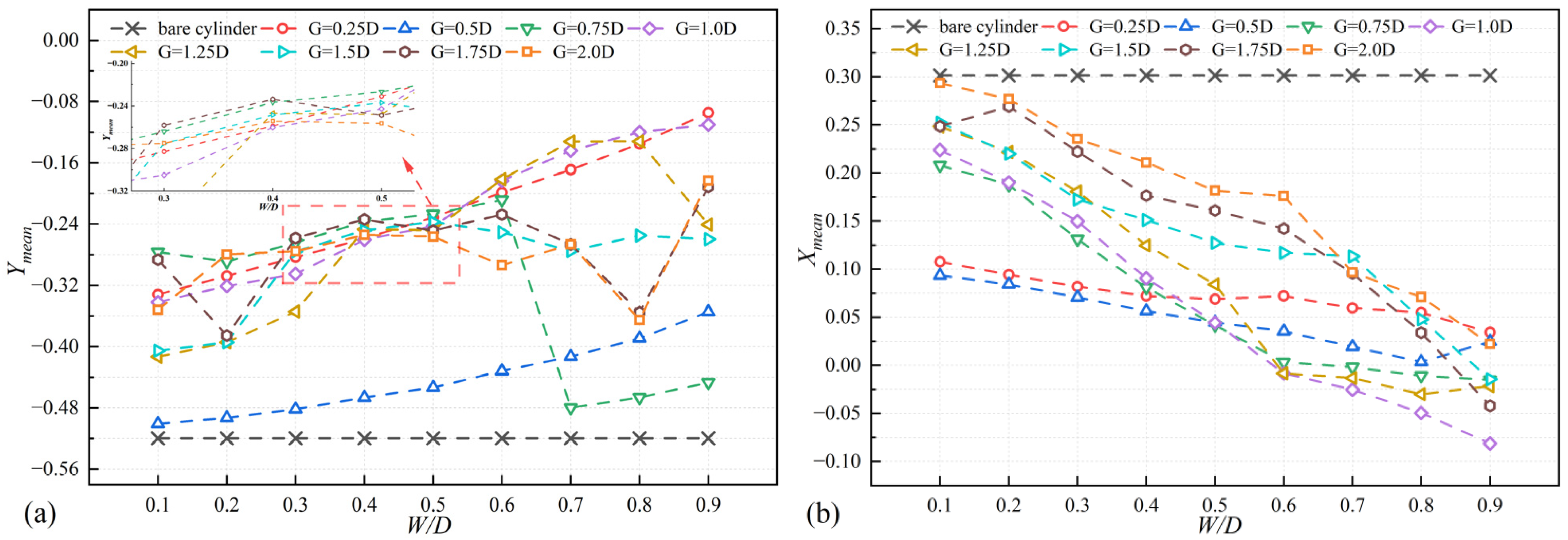
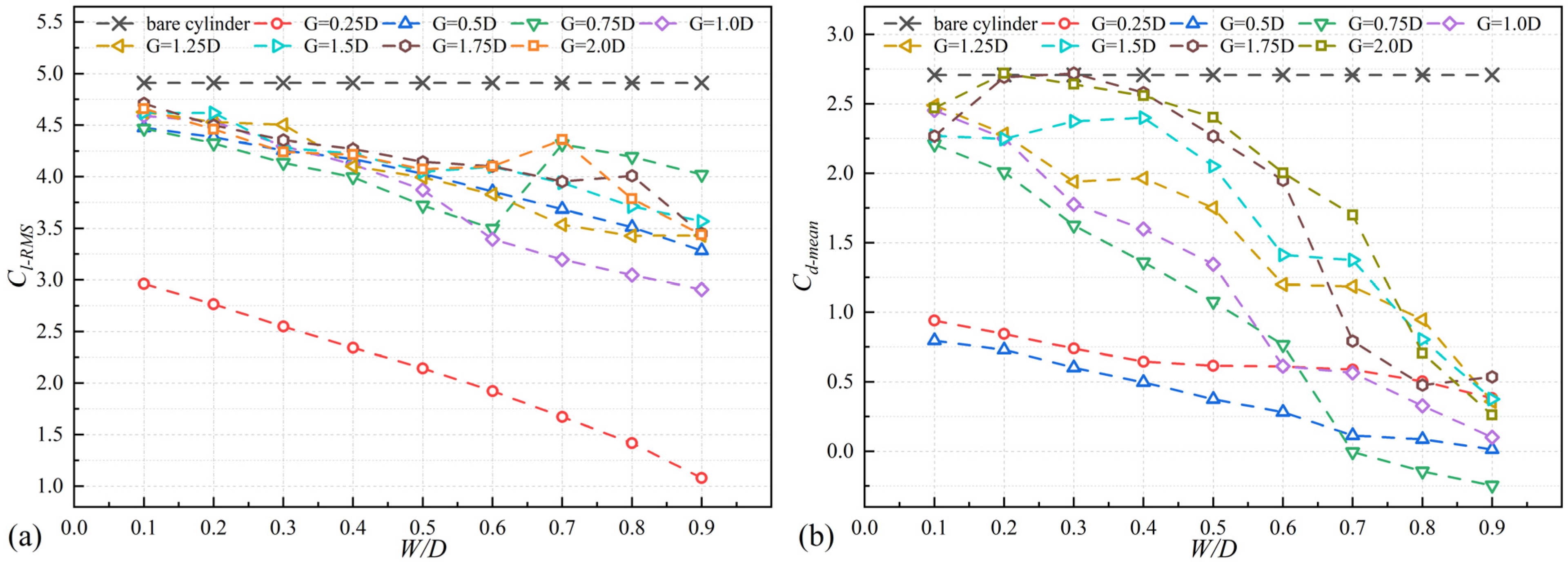
There is a clear difference in amplitude and lift–drag curves between low gap distances and high gap distances. At low gap distances, the amplitude is low and increases with an increase in the width. In contrast, at high gap distances, the amplitude is high and less influenced by the width. At low gap distances (G/D = 0.25, 0.5), both cross-flow and in-line displacements change smoothly with minimal variation. For high gap distances (G/D > 0.5), selecting an appropriate width can achieve in-line mean displacement (Xmean) of 0. Both the mean drag coefficient (Cd-mean), and the root mean square of the lift coefficient (Cl-RMS) shows a decreasing trend as the width increases. The width has a significant suppression effect on Cd-mean and Cl-RMS.
(2)
Six different wake patterns are observed under different gap distances and widths. Changes in gap distance and width can lead to transformations in wake patterns. At gap distances of G/D = 0.25 and 0.5, the wake pattern remains a stable 2S pattern regardless of the width. For G/D = 0.75, when the width (W/D) reaches 0.7, the vortex shedding pattern transitions from the original P+S pattern to a 2S pattern. For G/D = 1.75, with an increase in the width, the vortex shedding pattern shifts from the original T+P pattern to a 2P pattern, and one negative vortice that detaches from the upstream splitter plate disappears. The number of shedding vortices increases, along with their merging and disappearance, combined with the interactions between vortice force fields, results in increasingly complex and unstable vortex shedding behaviors. The complex and unstable vortex behaviors can lead to uneven forces and amplify the vibration response of the cylinder, which compromises structure stability.
(3)
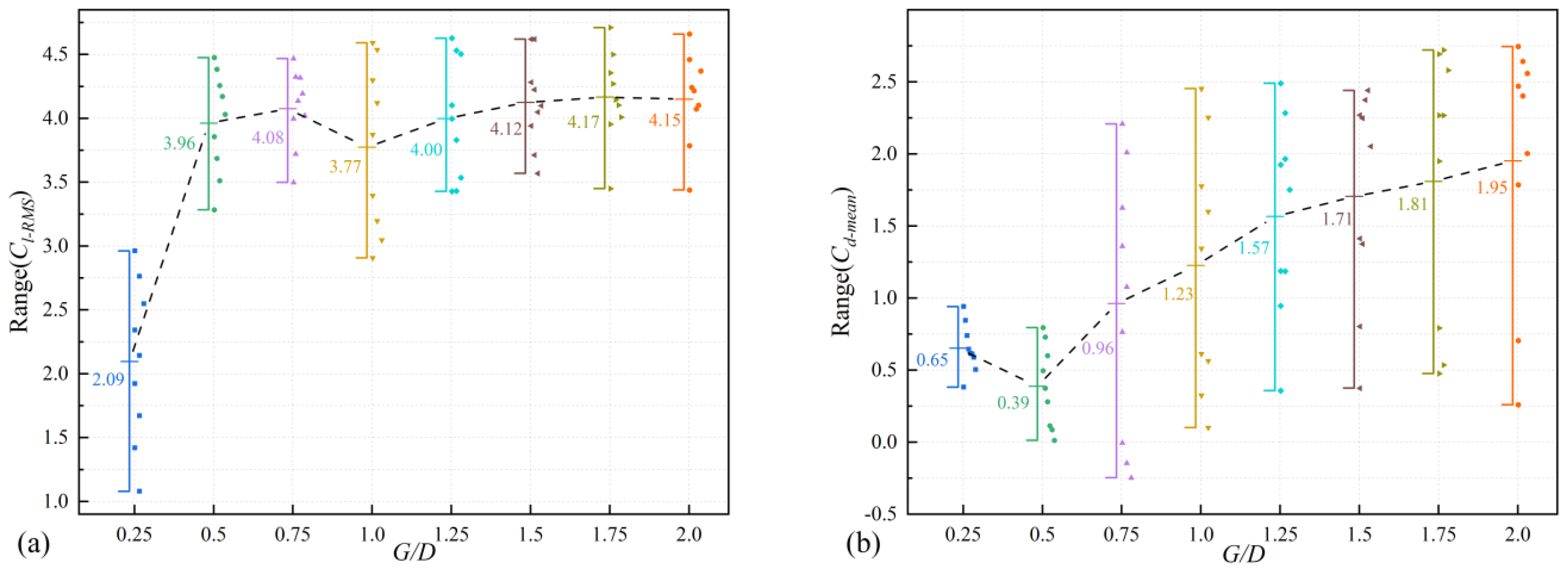
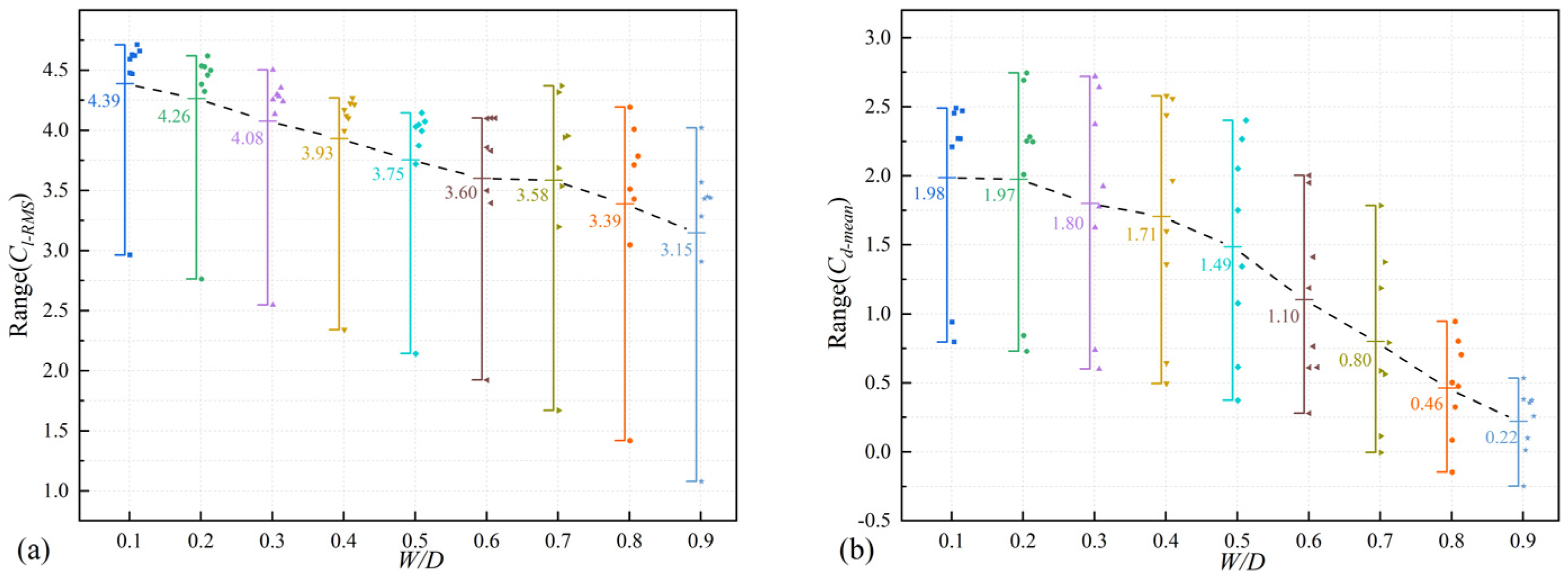
The sensitivity of lift and drag coefficients to variations in gap distance and width differs. For gap distances greater than 0.25, the lift coefficient is generally sensitive to changes in the width and the sensitivity of the drag coefficient to the width increases as the width increases. Conversely, the lift coefficient shows little sensitivity to changes in the gap distances and the sensitivity of the drag coefficient to the gap distance decreases as the width increases.
(4)
For the suppression of amplitudes, with low gap distances (G/D = 0.25, 0.5), the amplitude suppression is more effective at G/D = 0.5 compared to G/D = 0.25. Effective amplitude suppression can be achieved across all tested width (W/D = 0.1–0.9), with small width providing better suppression effects. When using high gap distances, for G/D = 0.75, effective suppression of both cross-flow and in-line amplitudes can be achieved with width from 0.7 to 0.9. At G/D values of 1.5, 1.75, and 2.0, there is a significant reduction in amplitude when W/D is set to 0.8. Specifically, at G/D = 1.25 and W/D = 0.9. In summary, it is advisable to use configurations where W/D ranges from 0.1 to 0.6 and G/D is 0.5, or where W/D ranges from 0.7 to 0.9 and G/D is 0.75. These setups offer comparable levels of amplitude suppression, achieving effective vibration suppression.

Author Contributions

Investigation, Validation, Writing—original draft, Formal analysis, J.L., Z.S., Y.Y. and Y.H.; Supervision, Writing—review and editing, W.C.; Writing—review and editing, J.S., Q.Q. and B.W.; Writing—review and editing, Supervision, X.L. All authors have read and agreed to the published version of the manuscript.

Funding

This research was funded by National Natural Science Foundation of China (52201334), State Key Laboratory of Ocean Engineering (Shanghai Jiao Tong University: Grant No. GKZD010087) and National College Students’ innovation and entrepreneurship training program (202410497103).

Data Availability Statement

The authors declare that the data presented in this study are available on request.

Acknowledgments

During the preparation of this study, the authors used Fluent 2022 R1, ICEM CFD 2022 R1 for the purposes of numerical experience. The authors have reviewed and edited the output and take full responsibility for the content of this publication.

Conflicts of Interest

The authors declare no conflicts of interest. The funders had no role in the design of the study; in the collection, analyses, or interpretation of data; in the writing of the manuscript; or in the decision to publish the results.

Abbreviations

ReReynolds number
G / D Gap distance
L / D Length of plate
W / D Width of plate
α Rotation rate
V r Reduced velocity
m Mass ratio
C l Lift coefficient
C d Drag coefficient
C l R M S The root mean square of the lift coefficient
C d m e a n Time-averaged drag coefficient
k Spring constant
c Damping coefficient
D Diameter of the cylinder
ρ Density of the fluid
ζ Damping ratio
S t Strouhal number
U Uniform incoming fluid velocity
Ω Angular velocity
vKinematic viscosity
A y / D Cross-flow amplitude
A x / D In-line amplitude
Y m e a n Cross-flow mean displacement
X m e a n In-line mean displacement
Ymean-ABSabsolute value of cross-flow mean displacement
Xmean-ABSabsolute value of in-line mean displacement

References

  1. Jeng, D.-S.; Zhang, H. An integrated three-dimensional model of wave-induced pore pressure and effective stresses in a porous seabed: II. Breaking waves. Ocean Eng. 2005, 32, 1950–1967. [Google Scholar] [CrossRef]
  2. Trim, A.D.; Braaten, H.; Lie, H.; Tognarelli, M.A. Experimental investigation of vortex-induced vibration of long marine risers. J. Fluids Struct. 2005, 21, 335–361. [Google Scholar] [CrossRef]
  3. Zhao, M. A review of recent studies on the control of vortex-induced vibration of circular cylinders. Ocean Eng. 2023, 285, 115389. [Google Scholar] [CrossRef]
  4. Wu, H.; Sun, D.P.; Lu, L.; Teng, B.; Tang, G.Q.; Song, J.N. Experimental investigation on the suppression of vortex-induced vibration of long flexible riser by multiple control rods. J. Fluids Struct. 2012, 30, 115–132. [Google Scholar] [CrossRef]
  5. Lu, L.; Liu, M.; Teng, B.; Cui, Z.; Tang, G.; Zhao, M.; Cheng, L. Numerical investigation of fluid flow past circular cylinder with multiple control rods at low Reynolds number. J. Fluids Struct. 2014, 48, 235–259. [Google Scholar] [CrossRef]
  6. Zhu, H.; Yao, J. Numerical evaluation of passive control of VIV by small control rods. Appl. Ocean Res. 2015, 51, 93–116. [Google Scholar] [CrossRef]
  7. Chen, W.; Bao, Y.; Chai, W.; Li, J.; Rheem, C.K.; Lin, Y.; Li, X. Investigation of the combined effect of control rods and forced rotation on a cylinder. Phys. Fluids 2023, 35, 103605. [Google Scholar] [CrossRef]
  8. Ishihara, T.; Li, T. Numerical study on suppression of vortex-induced vibration of circular cylinder by helical wires. J. Wind Eng. Ind. Aerodyn. 2020, 197, 104081. [Google Scholar] [CrossRef]
  9. Hao, Z.; Sun, C.; Lu, Y.; Bi, K.; Zhou, T. Suppression of vortex-induced vibration and phase-averaged analysis of the wake generated by a circular cylinder covered with helical grooves. Fluids 2022, 7, 194. [Google Scholar] [CrossRef]
  10. Xu, W.; Luan, Y.; Liu, L.; Wu, Y.X. Influences of the helical strake cross-section shape on vortex-induced vibrations suppression for a long flexible cylinder. China Ocean Eng. 2017, 31, 438–446. [Google Scholar] [CrossRef]
  11. Zhu, H.; Gao, Y.; Zhou, T. Flow-induced vibration of a locally rough cylinder with two symmetrical strips attached on its surface: Effect of the location and shape of strips. Appl. Ocean Res. 2018, 72, 122–140. [Google Scholar] [CrossRef]
  12. Chen, W.; Wang, S.; Shi, X.; Rheem, C.K.; Lin, Y.; Liu, E. Numerical simulation of surface roughness effects on the vortex-induced vibration of a circular cylinder at a subcritical Reynolds number. Int. J. Nav. Archit. Ocean Eng. 2022, 14, 100430. [Google Scholar] [CrossRef]
  13. Chen, W.; Du, A.; Lin, Y.; Shao, J.; Gu, J.; Gong, J.; Rheem, C.K.; Wen, B.; Li, X. Investigation of vortex-induced vibrations of rotating cylinders with different surface roughnesses. Phys. Fluids 2024, 36, 043614. [Google Scholar] [CrossRef]
  14. Sun, C.; Zhou, T.; An, H.; Zhu, H.; Cheng, L. On the study of vortex-induced vibration of circular cylinders covered with different roughness. Appl. Ocean Res. 2022, 124, 103215. [Google Scholar] [CrossRef]
  15. Sun, Y.; Wang, J.; Fan, D.; Zheng, H.; Hu, Z. The roles of rigid splitter plates in flow-induced vibration of a circular cylinder. Phys. Fluids 2020, 34, 114114. [Google Scholar] [CrossRef]
  16. Zhu, H.; Liu, W. Flow control and vibration response of a circular cylinder attached with a wavy plate. Ocean Eng. 2020, 212, 107537. [Google Scholar] [CrossRef]
  17. Zeng, L.; Zhao, F.; Wang, H.; Liu, Y.; Tang, H. Control of flow-induced vibration of a circular cylinder using a splitter plate. Phys. Fluids 2023, 35, 087104. [Google Scholar] [CrossRef]
  18. Zhu, H.; Li, G.; Wang, J. Flow-induced vibration of a circular cylinder with splitter plates placed upstream and downstream individually and simultaneously. Appl. Ocean Res. 2020, 97, 102084. [Google Scholar] [CrossRef]
  19. Sarpkaya, T. A critical review of the intrinsic nature of vortex-induced vibrations. J. Fluids Struct. 2004, 19, 389–447. [Google Scholar] [CrossRef]
  20. Williamson, C.H.K.; Govardhan, R. Vortex-induced vibrations. Annu. Rev. Fluid Mech. 2004, 36, 413–455. [Google Scholar] [CrossRef]
  21. Guan, G.; He, K.; Wang, P.; Yang, Q. Study on the parameters of detached splitter plate for VIV suppression. Ocean Eng. 2022, 266, 113092. [Google Scholar] [CrossRef]
  22. Zhu, H.; Chen, Q.; Tang, T.; Alam, M.M.; Zhou, T. Flow structures around a circular cylinder with bilateral splitter plates and their dynamic characteristics. Ocean Eng. 2023, 269, 113547. [Google Scholar] [CrossRef]
  23. Chen, J.; Wu, J. Control of flow-induced vibration of a circular cylinder with a porous splitter plate. Ocean Eng. 2023, 281, 114780. [Google Scholar] [CrossRef]
  24. Mittal, C.; Sharma, A. Flow-induced vibration of a flexible splitter-plate in the wake of a stationary cylinder. Phys. Fluids 2021, 33, 113607. [Google Scholar] [CrossRef]
  25. Cui, G.P.; Feng, L.H.; Hu, Y.W. Flow-induced vibration control of a circular cylinder by using flexible and rigid splitter plates. Ocean Eng. 2022, 249, 110939. [Google Scholar] [CrossRef]
  26. Liu, H.; Han, X.; Williams, J.J.R.; Xie, R.; Lin, P. 3D numerical study of splitter plate’s effect on a flexible cylinder VIV. Ocean Eng. 2023, 269, 113397. [Google Scholar] [CrossRef]
  27. Zhao, M.; Cheng, L.; An, H.; Lu, L. Three-dimensional numerical simulation of vortex-induced vibration of an elastically mounted rigid circular cylinder in steady current. J. Fluids Struct. 2014, 50, 292–311. [Google Scholar] [CrossRef]
  28. Ogunremi, A.R.; Sumner, D. The effect of a splitter plate on the flow around a finite prism. J. Fluids Struct. 2015, 59, 1–21. [Google Scholar] [CrossRef]
  29. Liang, S.; Wang, J.; Xu, B.; Wu, W.; Lin, K. Vortex-induced vibration and structure instability for a circular cylinder with flexible splitter plates. J. Wind Eng. Ind. Aerodyn. 2018, 174, 200–209. [Google Scholar] [CrossRef]
  30. Bao, Y.; Zhang, X.; Lin, Y.; Shao, J.; Chen, W.; Rheem, C.K.; Li, X. Investigation of coupled response on cylindrical eccentricity induced vibration and flow induced vibration. Ocean Eng. 2024, 305, 117978. [Google Scholar] [CrossRef]
  31. Zhang, X.; Li, J.; Zhang, W.; Shao, J.Y.; Chen, W.; Rheem, C.K.; Tang, G.; Li, X. Numerical investigation of the flow-induced vibration of a rotation pipe with internal flow. Ocean Eng. 2024, 294, 116809. [Google Scholar] [CrossRef]
  32. Du, L.; Sun, X. Suppression of vortex-induced vibration using the rotary oscillation of a cylinder. Phys. Fluids 2015, 27, 023603. [Google Scholar] [CrossRef]
  33. Bourguet, R.; Lo Jacono, D. Flow-induced vibrations of a rotating cylinder. J. Fluid Mech. 2014, 740, 342–380. [Google Scholar] [CrossRef]
  34. Bao, Y.; Lin, Y.; Chen, W.; Rheem, C.K.; Li, X. Numerical investigation of wake and flow-induced vibrations of a rotating cylinder in flow. Ocean Eng. 2022, 262, 112207. [Google Scholar] [CrossRef]
  35. Du, A.; Chen, W.; Lin, Y.; Chi, Q.; Rheem, C.K.; Wen, B.; Liu, Z.; Li, X. Vortex-induced vibration of a rotating cylinder with dual splitter plates. Phys. Fluids 2024, 36, 083623. [Google Scholar] [CrossRef]
  36. Tang, T.; Zhu, H.; Chen, Q.; Zhang, J.; Gao, Y. Dynamic response of a circular cylinder in the presence of a detached splitter plate: On the gap distance sensitivity. J. Fluids Struct. 2023, 119, 103888. [Google Scholar] [CrossRef]
  37. Zou, Q.; Ding, L.; Wang, H.; Wang, J.; Zhang, L. Two-degree-of-freedom flow-induced vibration of a rotating circular cylinder. Ocean Eng. 2019, 191, 106505. [Google Scholar] [CrossRef]
  38. Wong, K.W.L.; Zhao, J.; Jacono, D.L.; Thompson, M.C.; Sheridan, J. Experimental investigation of flow-induced vibration of a rotating circular cylinder. J. Fluid Mech. 2017, 829, 486–511. [Google Scholar] [CrossRef]
  39. Serson, D.; Meneghini, J.R.; Carmo, B.S.; Volpe, E.V.; Gioria, R.S. Wake transition in the flow around a circular cylinder with a splitter plate. J. Fluid Mech. 2014, 755, 582–602. [Google Scholar] [CrossRef]
  40. Dehkordi, B.G.; Jafari, H.H. On the suppression of vortex shedding from circular cylinders using detached short splitter-plates. J. Fluids Eng. 2010, 132, 044501. [Google Scholar] [CrossRef]
  41. Derakhshandeh, J.F.; Gharib, N. Numerical investigations on the flow control over bumped surface circular cylinders. Ocean Eng. 2021, 240, 109943. [Google Scholar] [CrossRef]
  42. Canuto, D.; Taira, K. Two-dimensional compressible viscous flow around a circular cylinder. J. Fluid Mech. 2015, 785, 349–371. [Google Scholar] [CrossRef]
  43. Bourguet, R. Two-degree-of-freedom flow-induced vibrations of a rotating cylinder. J. Fluid Mech. 2020, 897, A31. [Google Scholar] [CrossRef]
  44. Gu, J.; Fernandes, A.C.; Han, X.; Kuang, X.; Chen, W. Numerical investigation of Reynolds number effects on vortex-induced vibrations at low and moderate Re regimes. Ocean Eng. 2022, 245, 110535. [Google Scholar] [CrossRef]
  45. Brasa, M.; Chassaing, P.; Minh, H.H. Numerical study and physical analysis of the pressure and velocity fields in the near wake of a circular cylinder. J. Fluid Mech. 1986, 165, 79–130. [Google Scholar] [CrossRef]
  46. Bao, Y.; Zhou, D.; Tu, J.H. Flow interference between a stationary cylinder and an elastically mounted cylinder arranged in proximity. J. Fluids Struct. 2011, 27, 1425–1446. [Google Scholar] [CrossRef]
  47. Wu, J.; Shu, C.; Zhao, N. Numerical investigation of vortex-induced vibration of a circular cylinder with a hinged flat plate. Phys. Fluids 2014, 26, 063601. [Google Scholar] [CrossRef]
  48. Zhao, M.; Cheng, L.; Lu, L. Vortex induced vibrations of a rotating circular cylinder at low Reynolds number. Phys. Fluids 2014, 26, 073602. [Google Scholar] [CrossRef]
  49. Li, R.; Gong, J.; Chen, W.; Li, J.; Chai, W.; Rheem, C.K.; Li, X. Numerical Investigation of Vortex-Induced Vibrations of a Rotating Cylinder near a Plane Wall. J. Mar. Sci. Eng. 2023, 11, 1202. [Google Scholar] [CrossRef]
Figure 1. Layout diagram of the cylinder and splitter plates.
Jmse 13 00971 g001
Figure 2. Computational domain with 30D wide and 15D + 50D long and boundary conditions.
Jmse 13 00971 g002
Figure 3. Computational mesh: (a) entire mesh and (b) near cylinder mesh.
Jmse 13 00971 g003
Figure 4. (a) Comparison of cross-flow amplitudes to those obtained by Bao et al. [34] at Re = 200, m* = 2.6 and α = 1 ; (b) cross-flow amplitudes of the bare cylinder at different rotation rates.
Jmse 13 00971 g004
Figure 5. The vibration responses of the rotating cylinder with different widths and gap distances at V r = 5 and α = 2 : (a) cross-flow direction; (b) in-line direction.
Jmse 13 00971 g005
Figure 6. The Ymean and Xmean of the rotating cylinder at different widths and gap distances at Vr = 5 and α = 2 : (a) cross-flow direction (b) in-line direction.
Jmse 13 00971 g006
Figure 7. The hydrodynamic coefficients with different widths and gap distances at Vr = 5 and α = 2 : (a) root mean square of the lift coefficients; (b) time-averaged drag coefficients.
Jmse 13 00971 g007
Figure 8. Time histories of the lift and drag coefficients of the rotating cylinder at different gap distances at Vr = 5 and α = 2 : (a) G/D = 0.25; (b) G/D = 1; (c) G/D = 1.5; (d) G/D = 2.
Jmse 13 00971 g008
Figure 9. The vibration trajectories of the rotating cylinder at Vr = 5 and α = 2 : bare cylinder and cylinder with dual splitter plates at different gap distances and widths. Red circle: W = 0.1D; Blue circle: W = 0.2D; Green circle: W = 0.3D; Purple circle: W = 0.4D; Yellow circle: W = 0.5D; Azure circle: W = 0.6D; Brown circle: W = 0.7D; Light yellow circle: W = 0.8D; Orange circle: W = 0.9D; Black circle: W = 0 (bare cylinder).
Jmse 13 00971 g009
Figure 10. The instantaneous vorticity contours of a cylinder moving towards its equilibrium position in the cross-flow direction at Vr = 5 and α = 2 . Red vortices: positive vortices; Blue vortices: negative vortices.
Jmse 13 00971 g010
Figure 11. Wake pattern map with different gap distances and widths at Vr = 5 and α = 2 .
Jmse 13 00971 g011
Figure 12. Time histories of the amplitude and force coefficients and evolution of the wake structures for the 2S pattern at Vr = 5 and α = 2 (G/D = 0.25 and W/D = 0.5): (a) lowest position; (b) equilibrium position; (c) highest position; (d) equilibrium position.
Jmse 13 00971 g012
Figure 13. Time histories of the amplitude and force coefficients and evolution of the wake structures for the P+T pattern at Vr = 5 and α = 2 (G/D = 1.25 and W/D = 0.7): (a) equilibrium position; (b) highest position; (c) equilibrium position; (d) lowest position.
Jmse 13 00971 g013
Figure 14. Time histories of the amplitude and force coefficients and evolution of the wake structures for the T+P pattern at Vr = 5 and α = 2 (G/D = 1.75 and W/D = 0.3): (a) lowest position; (b) equilibrium position; (c) highest position; (d) equilibrium position.
Jmse 13 00971 g014
Figure 15. The cross-flow amplitudes and lift coefficients for G/D = 0.75 with different widthsat Vr = 5 and α = 2 : (ad) W/D = 0.6; (eh) W/D = 0.7.
Jmse 13 00971 g015aJmse 13 00971 g015b
Figure 16. Cross-flow amplitude, cross-flow mean displacement, RMS of the lift coefficients and wake patterns of the cylinder with G/D = 1.0, 1.5, and 1.75 at different widths at Vr = 5 and α = 2 .
Jmse 13 00971 g016
Figure 17. The distribution ranges of hydrodynamics coefficients under different gap distances at Vr = 5 and α = 2 : (a) root mean square of lift coefficients; (b) time-average drag coefficients.
Jmse 13 00971 g017
Figure 18. The distribution ranges of hydrodynamics coefficients under different widths at Vr = 5 and α = 2 : (a) root mean square of lift coefficients; (b) time-average drag coefficients.
Jmse 13 00971 g018
Table 1. Mesh sizes of the different areas.
Mesh Δ x / D
(A)(B)(C)
SIZE I 0.02–0.050.05–0.100.10–0.30
SIZE II 0.04–0.080.08–0.160.16–0.40
SIZE III 0.05–0.100.10–0.200.20–0.50
SIZE IV 0.10–0.200.20–0.400.40–0.70
SIZE V 0.20–0.300.30–0.500.50–0.80
Table 2. Parameters and comparison of flow through the cylinder with Re = 200.
CaseMesh C d m e a n S t Elements
A1Size I1.330.19389,775
A2Size II1.340.19148,085
A3Size III1.360.1996,423
A4Size IV1.400.1922,374
A5Size V1.420.204743
Braza et al. [45] 1.380.20\
Disclaimer/Publisher’s Note: The statements, opinions and data contained in all publications are solely those of the individual author(s) and contributor(s) and not of MDPI and/or the editor(s). MDPI and/or the editor(s) disclaim responsibility for any injury to people or property resulting from any ideas, methods, instructions or products referred to in the content.

